Navigation

    • Register
    • Login
    • OpenHardware.io
    • Categories
    • Recent
    • Tags
    • Popular
    1. Home
    2. petewill
    3. Topics
    • Profile
    • Following
    • Followers
    • Topics
    • Posts
    • Best
    • Groups

    Topics created by petewill

    • petewill

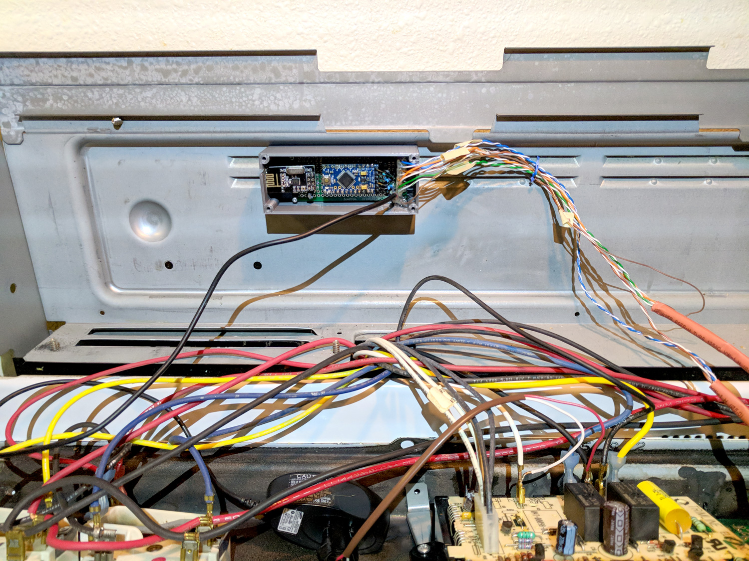
      How To: Automate Devices with Existing Buttons
      My Project • • petewill  

      6
      6
      Votes
      6
      Posts
      3975
      Views

      pioneer_shahid

      @petewill Thanks for sharing your knowledge. I am picking this after 2.5 years as this is what I would like to build. i have established my switch is connected to grounds and build a prototype successfully. However, my issue is the code as i am lacking in the software side and appreciate if @petewill or someone else can advise me. Issue 1: when i press the button, it shows twice in the log and i can see the communicating successfully with the gateway. Issue 2: when i send the command via mqtt it is not turning on the led. Thanks for input in advance. my code is as follows, #define SKETCH_NAME "Oven Control" #define SKETCH_VERSION "1.0" // Enable debug prints to serial monitor #define MY_DEBUG //MySensors debug messages //#define LOCAL_DEBUG //Code specific debug messages // Enable and select radio type attached #define MY_RADIO_RF24 //#define MY_RADIO_RFM69 #define MY_RF24_PA_LEVEL RF24_PA_HIGH //Options: RF24_PA_MIN, RF24_PA_LOW, RF24_PA_HIGH, RF24_PA_MAX #define MY_RF24_CHANNEL 76 #define MY_NODE_ID 4 //Manually set the node ID here. Comment out to auto assign #include <MySensors.h> #include <Bounce2.h> #ifndef BAUD_RATE #define BAUD_RATE 115200 #endif #ifdef LOCAL_DEBUG #define dbg(...) Serial.print(__VA_ARGS__) #define dbgln(...) Serial.println(__VA_ARGS__) #else #define dbg(x) #define dbgln(x) #endif #define DWELL_TIME 50 //value used in all wait calls (in milliseconds) this allows for radio to come back to power after a transmission, ideally 0 #define CHILD_ID_OVEN 0 #define GND_GATE_PIN 3 #define GND_DETECT_PIN 4 #define BUTTON_PRESS_DELAY 100 //The amount of delay used for a button press //Track button presses uint8_t gndValuePrev = 1; //LED button on/off tracking uint8_t gndLedOn = 0; unsigned long gndMillis; // Instantiate a Bounce object Bounce gndDebouncer = Bounce(); Bounce vccDebouncer = Bounce(); MyMessage msgHeatMode(CHILD_ID_OVEN, V_HVAC_FLOW_STATE); void setup() { Serial.begin(115200); //Setup the pins pinMode(GND_GATE_PIN, OUTPUT); pinMode(GND_DETECT_PIN, INPUT_PULLUP); //Start with all outputs (buttons) not enabled (pressed) digitalWrite(GND_GATE_PIN, 0); // After setting up the buttons, setup debouncers gndDebouncer.attach(GND_DETECT_PIN); gndDebouncer.interval(50); } void presentation() { // Send the sketch version information to the gateway sendSketchInfo(SKETCH_NAME, SKETCH_VERSION); // Register all sensors to gw (they will be created as child devices) present(CHILD_ID_OVEN, S_HEATER); wait(DWELL_TIME); //metric = getConfig().isMetric; //This has been removed as it will default to metric if connection to the gateway is not established (bad for imperial users) //wait(DWELL_TIME); } void loop() { unsigned long currentMillis = millis(); //Get the current millis (used for timers) // Update the debouncers gndDebouncer.update(); // Get the update value uint8_t gndValue = gndDebouncer.read(); if (gndValue != gndValuePrev) { if (gndValue == 0) { Serial.println(F("Ground Button Pressed")); if (gndLedOn == 0) { //Don't echo the button push if it was turned on by the Arduino gndMillis = currentMillis + 1000; gndLedOn = 1; } } gndValuePrev = gndValue; send(msgHeatMode.set(gndLedOn == 1 ? "HeatOn" : "Off")); dbgln(gndValue); } //Turn on led 1 second after button pressed if (gndLedOn == 1 && currentMillis > gndMillis) { nChannelPress(GND_GATE_PIN); gndLedOn = 0; } } void nChannelPress(uint8_t buttonPinName) { //Simulate a button press digitalWrite(buttonPinName, 1); //VCC to disable delay(BUTTON_PRESS_DELAY); digitalWrite(buttonPinName, 0); //Ground to enable delay(BUTTON_PRESS_DELAY); } The log is as follows, 22:35:51.655 -> 2189 TSF:MSG:SEND,4-4-0-0,s=255,c=3,t=11,pt=0,l=12,sg=0,ft=0,st=OK:Oven Control 22:35:51.655 -> 2198 TSF:MSG:SEND,4-4-0-0,s=255,c=3,t=12,pt=0,l=3,sg=0,ft=0,st=OK:1.0 22:35:51.655 -> 2206 TSF:MSG:SEND,4-4-0-0,s=0,c=0,t=14,pt=0,l=0,sg=0,ft=0,st=OK: 22:35:51.724 -> 2262 MCO:REG:REQ 22:35:51.724 -> 2265 TSF:MSG:SEND,4-4-0-0,s=255,c=3,t=26,pt=1,l=1,sg=0,ft=0,st=OK:2 22:35:51.724 -> 2276 TSF:MSG:READ,0-0-4,s=255,c=3,t=27,pt=1,l=1,sg=0:1 22:35:51.724 -> 2281 MCO:PIM:NODE REG=1 22:35:51.724 -> 2283 MCO:BGN:STP 22:35:51.758 -> 2285 MCO:BGN:INIT OK,TSP=1 22:35:52.541 -> Ground Button Pressed 22:35:52.541 -> 3073 TSF:MSG:SEND,4-4-0-0,s=0,c=1,t=21,pt=0,l=6,sg=0,ft=0,st=OK:HeatOn 22:35:52.745 -> 3291 TSF:MSG:SEND,4-4-0-0,s=0,c=1,t=21,pt=0,l=6,sg=0,ft=0,st=OK:HeatOn 22:39:09.887 -> 200479 TSF:MSG:READ,0-0-4,s=255,c=3,t=6,pt=0,l=0,sg=0: 22:42:23.738 -> 394357 TSF:MSG:READ,0-0-255,s=255,c=3,t=20,pt=0,l=0,sg=0: 22:42:23.738 -> 394362 TSF:MSG:BC 22:42:23.895 -> 394502 TSF:MSG:SEND,4-4-0-0,s=255,c=3,t=21,pt=1,l=1,sg=0,ft=0,st=OK:0 22:44:19.647 -> Ground Button Pressed 22:44:19.647 -> 510285 TSF:MSG:SEND,4-4-0-0,s=0,c=1,t=21,pt=0,l=6,sg=0,ft=0,st=OK:HeatOn 22:44:19.958 -> 510600 TSF:MSG:SEND,4-4-0-0,s=0,c=1,t=21,pt=0,l=6,sg=0,ft=0,st=OK:HeatOn```
    • petewill

      Video How To: Battery Powered Chair Occupancy (Contact) Sensor
      My Project • • petewill  

      20
      8
      Votes
      20
      Posts
      10496
      Views

      Nca78

      @OliverDog when sending to gateway you cannot trust your multimeter. It's probably around 15mA but only during a fraction of a second, and what you read is some kind of average between that and the very low power consumption in sleep mode.
    • petewill

      Low Voltage Whole House Power Supply
      My Project • • petewill  

      13
      9
      Votes
      13
      Posts
      8462
      Views

      JonnyDev13

      @petewill Thanks for explaining. That will be helpful if I get to the point where I can try to do something like this!
    • petewill

      Help converting 24VAC to 5VDC
      Hardware • • petewill  

      15
      0
      Votes
      15
      Posts
      10985
      Views

      petewill

      @Sparkman Cool, thanks for sharing! It's always nice to have options.
    • petewill

      Use Node-Red to Allow Multiple Connections to Ethernet Gateway?
      Node-RED • • petewill  

      13
      0
      Votes
      13
      Posts
      8931
      Views

      Qu3Uk

      So I had a go at using SOCAT and although it's working it doesn't seem to like multiple connections on the TCP port. Although it will accept the connection it seems to output data from Serial>Ethernet is a round robin kind of way. Reason I had two connections to it was to ensure the pipe was always read as the other post it was mentioned if the pipe isn't cleared there would be memory problems and I noticed not all the data was getting to all the TCP connections.. Anyway here is the code if you want to check it out. Socat sudo socat PTY,link=/dev/ttyS81,mode=666,group=dialout,raw TCP-LISTEN:40501,fork,reuseaddr & sudo socat PTY,link=/dev/ttyS82,mode=666,group=dialout,raw TCP-LISTEN:40502,fork,reuseaddr & NodeRead [{"id":"e9998a90.266cc8","type":"serial-port","z":"a89027d9.b1ef08","serialport":"/dev/ttyS82","serialbaud":"9600","databits":"8","parity":"none","stopbits":"1","newline":"\\n","bin":"false","out":"char","addchar":true},{"id":"ee7d4fbe.58c5f","type":"serial-port","z":"a89027d9.b1ef08","serialport":"/dev/ttyS81","serialbaud":"9600","databits":"8","parity":"none","stopbits":"1","newline":"\\n","bin":"false","out":"char","addchar":true},{"id":"50839f8a.fbcaa","type":"debug","z":"a89027d9.b1ef08","name":"Full-Debug","active":true,"console":"false","complete":"true","x":595,"y":575,"wires":[]},{"id":"d5b18044.18e1f","type":"tcp in","z":"a89027d9.b1ef08","name":"MYS-GW-OUT","server":"client","host":"192.168.1.150","port":"5003","datamode":"stream","datatype":"utf8","newline":"\\n","topic":"MYS-GW-Output","base64":false,"x":103,"y":963,"wires":[["db05059b.37e4e8","4f3b7e79.739e6"]]},{"id":"c462686d.bb5a78","type":"catch","z":"a89027d9.b1ef08","name":"","scope":null,"x":387,"y":574,"wires":[["50839f8a.fbcaa"]]},{"id":"9fdda3da.86eb7","type":"debug","z":"a89027d9.b1ef08","name":"PayloadDebug","active":true,"console":"false","complete":"payload","x":584,"y":666,"wires":[]},{"id":"db05059b.37e4e8","type":"serial out","z":"a89027d9.b1ef08","name":"ControllerOne-Out","serial":"ee7d4fbe.58c5f","x":619,"y":875,"wires":[]},{"id":"75f6db75.bba3c4","type":"serial in","z":"a89027d9.b1ef08","name":"ControllerOne-IN","serial":"ee7d4fbe.58c5f","x":103,"y":894,"wires":[["6bbbe087.e897"]]},{"id":"6bbbe087.e897","type":"tcp out","z":"a89027d9.b1ef08","host":"192.168.1.150","port":"5003","beserver":"client","base64":false,"end":false,"name":"MYS-GW-IN","x":605,"y":949,"wires":[]},{"id":"4f3b7e79.739e6","type":"serial out","z":"a89027d9.b1ef08","name":"ControllerTwo-Out","serial":"e9998a90.266cc8","x":625,"y":1044,"wires":[]},{"id":"73b94814.883c88","type":"serial in","z":"a89027d9.b1ef08","name":"ControllerTwo-IN","serial":"e9998a90.266cc8","x":104,"y":1045,"wires":[["6bbbe087.e897"]]},{"id":"8121ed9b.ba597","type":"tcp in","z":"a89027d9.b1ef08","name":"ControllerOne-TCP-Out","server":"client","host":"127.0.0.1","port":"40501","datamode":"stream","datatype":"utf8","newline":"\\n","topic":"","base64":false,"x":151,"y":731,"wires":[["9fdda3da.86eb7"]]}]
    • petewill

      Video How To - Monitor your Refrigerator
      My Project • • petewill  

      37
      9
      Votes
      37
      Posts
      39759
      Views

      Newzwaver

      Hi And thanks for the reply, I do have the PT1000 as well as those sensors. The only thing is I am trying to find a use for the PT1000. I have already placed one in my deep freeze and one out door but have several more that I just want to use. It's not the cost as most of the projects on this are cheap, it's the challenge of getting it done. Thanks again, I
    • petewill

      Video How To - Phoney TV
      My Project • • petewill  

      22
      9
      Votes
      22
      Posts
      13282
      Views

      tombstone

      another nice video
    • petewill

      How To - Doorbell Automation Hack
      My Project • • petewill  

      106
      9
      Votes
      106
      Posts
      93493
      Views

      flopp

      @flopp Found one mistake. I wrote some Serial.print to see where in the code my problem was and I wrote in a wrong place, so the code was looping on a wrong way. When that was corrected I found out that my relay needed to get 1 when it was off, so I just changed to below and now I don't get a green light as soon as I power on the arduino #define RELAY_ON 0 #define RELAY_OFF 1
    • petewill

      How To: Make a Simple/Cheap Scene Controller (with video)
      My Project • • petewill  

      62
      9
      Votes
      62
      Posts
      40076
      Views

      Sanderunizuki

      I want to use this mysensors touch sensor to adjust a selector switch in domoticz, so if I select scene 1 the selector switch in Domoticz goes to 10%, and scene 2 to 20% and so on. Is that possible and how do I do that?
    • petewill

      Video How To - Monitor your Smoke/Carbon Monoxide Alarm
      My Project • • petewill  

      18
      2
      Votes
      18
      Posts
      15980
      Views

      vecnar

      Hello, First of all I am a basic diy person so not much experience with electronics other than basic relays, some soldering and basic use of multi-meter. I have a brk smoke detectors throughout house and would like to trigger house alarm as it is connected to service that notifies me over the phone. I have looked online for information and stumbled on your video that looked similar to my needs but more so with Edward Cheung. Please advise where best to post this message as I think it may not be appropriate on mysensors.org. Initially I was thinking of using brk relay but it is rated for 120V AC, I am based in europe with 240V AC, I do not need to power anything with AC and I want it to work when the power is down as both smoke detectors and house alarm operate on batteries. I purchased the breadboard, 1k and 330 ohm resistors and 2 x PC817 4pin optocouplers without checking if my alarm is supporting normally open zones, it has normally closed options 4k7 resistor end of line and 2k2 resistor end of line and basic normally closed (breaking the circuit triggers alarm). Alarm zone is a 5 v DC circuit. Question: Any advice on how to get output pins to stay constantly closed and change state when alarm is triggered, should I buy some other optocoupler with 6 pins that has ability to change output contacts when energized or any other approach? Thank you, Oleg
    • petewill

      Safe In-Wall AC to DC Transformers??
      Hardware • • petewill  

      431
      0
      Votes
      431
      Posts
      457516
      Views

      TomG

      I emailed Hi-Link about the HLK-PW01 power supplies that @rmh, @yannik-mündler and myself purchased. These are the power supplies with a removable bottom. I sent the following email to Sunny at Hi-Link (contact info: http://www.hlktech.net/contact.php). ++++ Hello, Are the two HLK-PM01s in the attached images genuine Hi-Link parts? A major difference is the part on the right has a bottom cover that is easily removable. I bought the part on the left from an Aliexpress seller in July 2018. The part on the right was bought from the same Aliexpress seller in May 2019. Thank you very much for your help. ++++ Here is Sunny's reply: ++++ Now all of our module are use new version . The one you bought on 2019 is the new version, the old version is not used yet. By the way,May I know you are the final user or the reseller? If you are worried about it,you can buy from our website www.hlktech.net or our Aliexpress store https://hlktech.aliexpress.com/store/211069 directly. ++++ I went to the Aliexpress page in their email and found the HLK-PM01 page. On that page they say: ++++ Recently,there are many fake module in the market,in order to Standardize the market environment,keep benifit for the customers,We,Hi-Link,changed our module to the new but more quality version,the back of new version is show as the following picture,currently,the old version and new version were sent random,please pay attention to that!thank you very much! ++++ They also show images of the previous version (which we are all familiar with) and the new version (with the removable bottom). So, it appears the HLK-PW01 power supplies with the removable bottom, from a reliable vendor, or directly from Hi-Link, are genuine Hi-Link power supplies. Below is my two images of the bottom of the two genuine power supplies (old on the left, new on the right).
    • petewill

      Backlit Dimmable LED Mirror with Motion Sensor
      My Project • • petewill  

      43
      6
      Votes
      43
      Posts
      30865
      Views

      loralg

      @petewill @mfalkvidd After looking I have the 168.. I already have some more ordered that are the 328 though. I should have looked closer when I ordered the first batch. Thanks for the help! I figured it was probably something simple I had overlooked on my end.
    • petewill

      Cheap voice control using AutHomation, AutoVoice and Tasker (Video)
      Vera • • petewill  

      2
      5
      Votes
      2
      Posts
      2788
      Views

      Dheeraj

      Really nice... Gr8 work
    • petewill

      $8 Lamp (Outlet) "Smart Plug" Module
      My Project • • petewill  

      109
      8
      Votes
      109
      Posts
      97438
      Views

      petewill

      @jeremushka I haven't done it on the smart outlet but I did do it on my "Whole House Fan" project. You can check out the code from that if you're interested. Here is a link to the video if you wanted to check that out: https://youtu.be/KVsUe7sOCPo Also, just make sure you check out the specs on the acs712 and don't pass through more current than is safe. I don't remember the specs off the top of my head but I knew my whole house fan was safe because of what it would be drawing
    • petewill

      Finally upgrading to 1.4 and I have a couple of questions...
      General Discussion • • petewill  

      9
      0
      Votes
      9
      Posts
      2602
      Views

      petewill

      Well I decided not to try the multiple gateway method. Too many opportunities for me to screw something up. I decided to work on the code ahead of time and convert all sensors in a weekend. For the most part it was very smooth. I had two nodes that wouldn't communicate with the gateway then I figured out that they were trying to communicate with a node that I had inadvertently made into a relay node. Once I cleared Eeprom and re-uploaded the code they found the gateway and worked great. One node I still haven't figured out. It will update all sensors (I have a barometer, DHT22 and moisture sensor connected) but it stops after the first time. I haven't had time to try to debug but it was working fine in v1.3. I'll post back when I finally get it figured out in case it helps anyone else who still needs to upgrade.
    • petewill

      LED Light is getting very hot
      Hardware • • petewill  

      13
      0
      Votes
      13
      Posts
      9165
      Views

      petewill

      Just got some parts and did some more testing on this so I thought I'd post a reply. The good news is there appears to be a cheap fix. As @Hoffan suggested I did some research on LED drivers. I found this one to work in my testing so far: http://www.ebay.com/itm/181113937482. I have plugged it in directly to the 12V source for 3 hours and it gets warm (maybe 100 degrees Fahrenheit) but by no means hot. I still need to connect it into my sensor and get it working with PWM. My plan is to limit the current before the MOSFET. I hope it works! Thanks again for all the help and suggestions!
    • petewill

      Help with arrays and debouncing
      Development • • petewill  

      11
      0
      Votes
      11
      Posts
      4585
      Views

      Zeph

      @petewill said: Ok, looks like I was wrong again. Turns out was a bad wire (or wires) connecting the radio to the Mega. Either that or the Mega has some bad connections. Anyway, I switched out the wires and all is working again (for now). Loose wires are a bear to find at times - you do something (like adding a cap) and you think you fixed it. Then for no good reason the problem comes back. Been there.
    • petewill

      Wrong Child ID in Vera Logs
      Troubleshooting • • petewill  

      3
      0
      Votes
      3
      Posts
      1491
      Views

      petewill

      @hek And that is why I will never be a programmer... I must have looked at that code 4 times! Anyway, thanks! I'll change it tonight when I get home. Do you think it would be worth updating the example here: http://www.mysensors.org/build/binary to add a child id? I'm wondering if there may be other people out there that may make the same mistake as me. Thanks again for all you do. I love this stuff!
    • petewill

      Can I have too many relaying (repeater) nodes?
      Development • relay repeater • • petewill  

      6
      0
      Votes
      6
      Posts
      4384
      Views

      hek

      Be aware that sensor need to have 20 consecutive failed transmissions before starting to look for a new relaying node.
    • petewill

      Relay Actuator stops responding after a week or so
      Troubleshooting • • petewill  

      5
      0
      Votes
      5
      Posts
      1710
      Views

      BulldogLowell

      @petewill said: I have not put a capacitor between 3.3v and ground on the radio chip though. Is that what you're referring to? What version are you running that is working for you? Thanks! Yeah, putting the capacitor on the radio chip... it really improved the reliability of the radio, in my experience. I'm running libraries as attached: like you I don't want to have to do any sketch upgrades on the sensors.
    • petewill

      Controlling Blinds.com RF Dooya Motors with Arduino and Vera
      My Project • • petewill  

      90
      7
      Votes
      90
      Posts
      73902
      Views

      Antonio Schneider

      Hello everyone, Firstly, I apologize for reviving such an old thread, but I find myself in a unique situation and was hoping some of you might be able to help. I hope everyone's doing well. I have a specific inquiry that I couldn't find a recent solution for. Does anyone here know of a tool to generate "fake" Dooya remote (DC90) RF codes for curtains? I've acquired a few motors without controllers and am trying to integrate them with Home Assistant and Bradlink RF remote. Specifically, I'm searching for a way to generate codes for the Up, Down, Stop, and the "Set" button functions to configure curtain limits. Any insights or guidance would be immensely appreciated. Thank you so much in advance!