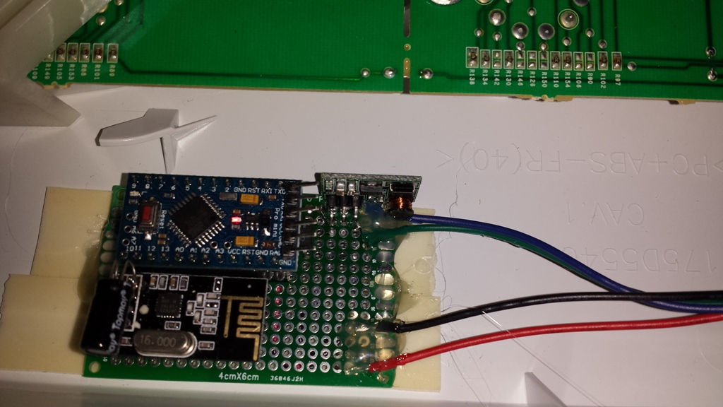
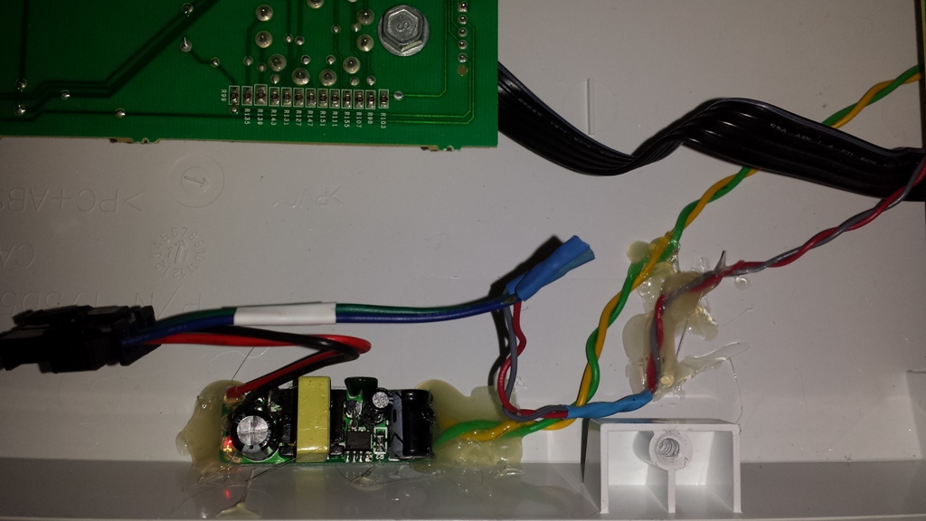
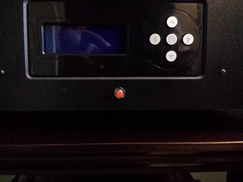
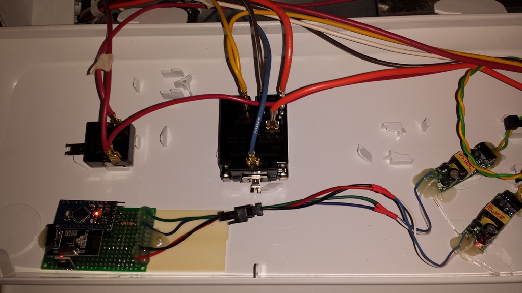
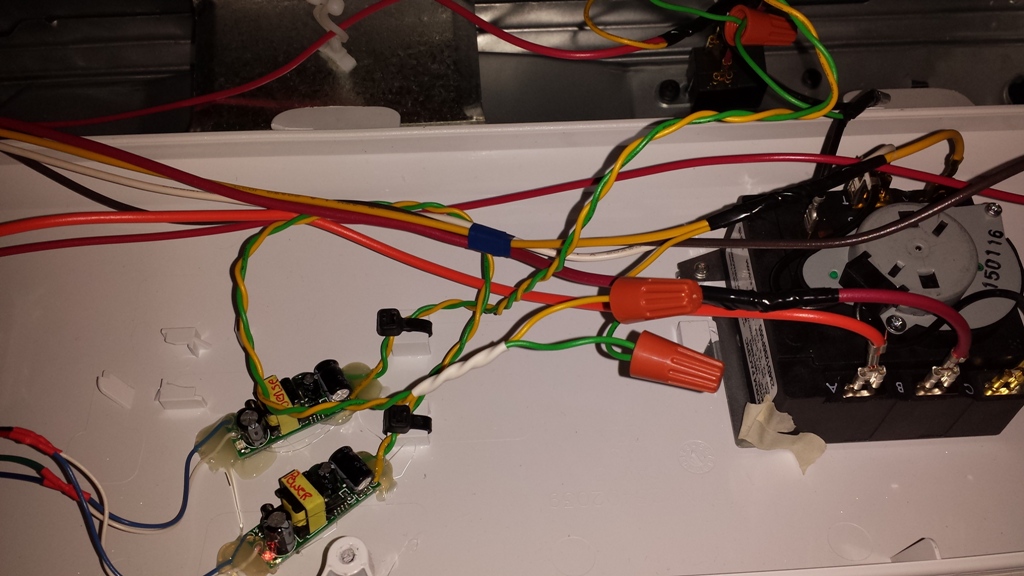
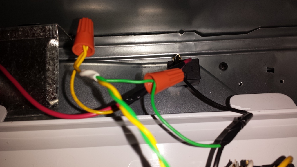
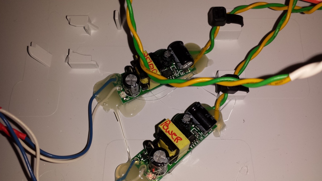
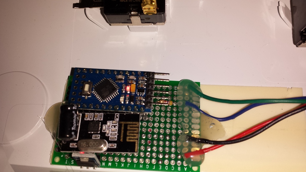
This is another very simple "Wash Cycle Completed" sensor. It's design uses the same Optocoupler sensing design I used in the Kiddie Smoke Detector project. The only difference is that I'm using 1 AC to DC transformer, and a boost module to boost the washer speaker power to fire the Optocoupler.
Parts:
- 1 Cheap AC/DC converter
- 1 Optocoupler
- 1 Step up Regulator
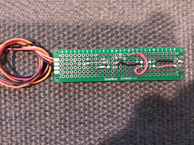
- 1 Small Proto Board.
- Some wire
Highlights:
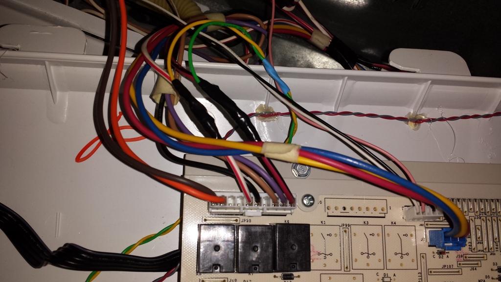
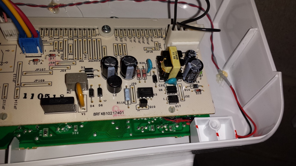
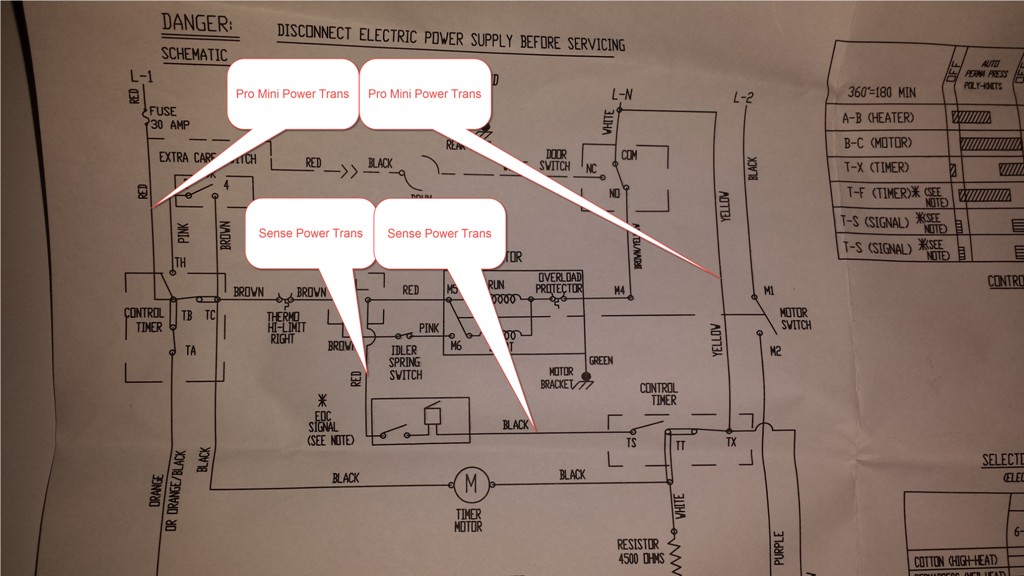
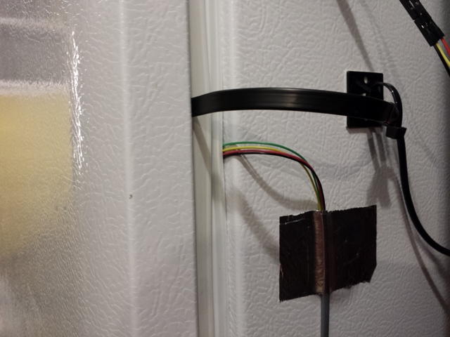
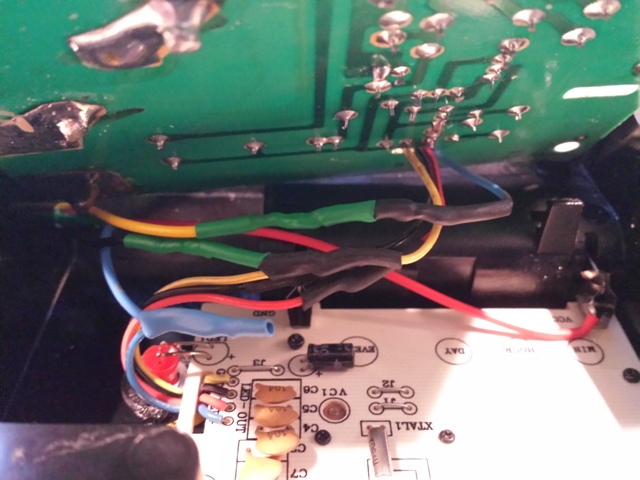
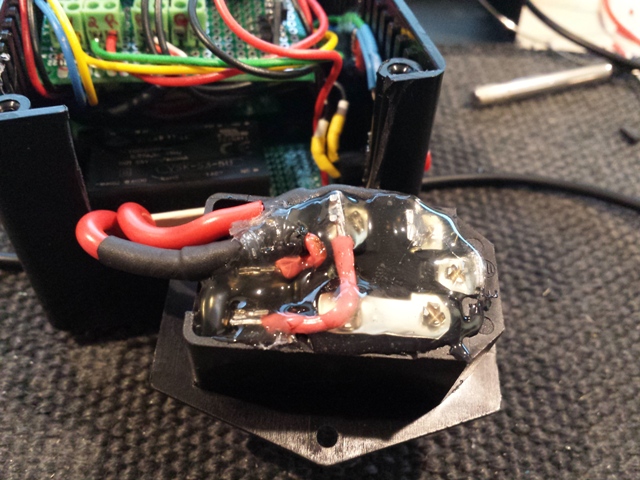
Use the Washers .5vdc Signal Piezo to interface with the Pro-Mini. The voltage to the Piezo is to low to drive the Optocoupler so I had to use a boost module to boost the voltage to the Optocoupler. I'm not sure what the long term effect will be on washers control board Piezo drive circuit, so I will follow up if I encounter a problem.
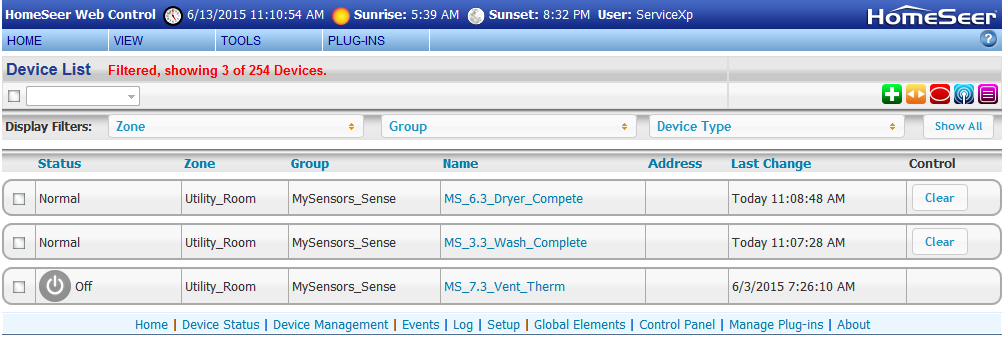
Again Uses the same sketch as the Kiddie Smoke Project, with the only change being to CYCLE_INTERVAL (For my dryer 3 works well)
Sketch:
// Based on Author: Patrick 'Anticimex' Fallberg Interrupt driven binary switch example with dual interrupts

#include <MySensor.h>
#include <SPI.h>

#define SKETCH_NAME "Washer End Cycle"
#define SKETCH_MAJOR_VER "1"
#define SKETCH_MINOR_VER "1"

#define CHILD_ID 3

#define SIREN_SENSE_PIN 3   // Arduino Digital I/O pin for optocoupler for siren

unsigned int SLEEP_TIME			= 32400; // Sleep time between reads (in seconds) 32400 = 9hrs?
long CYCLE_COUNTER					= 3;  // This is the number of times we want the Audio Counter to reach before triggering a signal to controller.
unsigned long CYCLE_INTERVAL		= 3; // How long do we want to watch once first detected (in seconds)
											//Adjust for your smoke detector, you want to pick up the siren signal at least 3 time to help stop false alarms.
unsigned long CYCLE_RATE			= 90; // How fast do we want to move checking the Pin state in the Status Check (in Millis) Adjust for your smoke detector
											//Adjust for your smoke detector, you want to pick up the siren signal at least 3 time to help stop false alarms.
unsigned long CYCLE_TIME_OKSTATUS	= 8; // How long do we want to watch for "all clear" once we have confirmed an Alarm (in seconds)
unsigned long CYCLE_RATE_OKSTATUS	= 500; // How fast do we want to move checking the Pin state when checking for an OK status (in Millis)

int oldValue=1;
int value=0;


MySensor sensor_node;
MyMessage msg(CHILD_ID, V_TRIPPED);

void setup()
{
	sensor_node.begin();
	// Setup the Siren Pin HIGH
	pinMode(SIREN_SENSE_PIN, INPUT_PULLUP);
	// Send the sketch version information to the gateway and Controller
	sensor_node.sendSketchInfo(SKETCH_NAME, SKETCH_MAJOR_VER"."SKETCH_MINOR_VER);
	sensor_node.present(CHILD_ID, S_SMOKE);
	//Send the state -- Always send Alarm state on power up.
	sensor_node.send(msg.setSensor(CHILD_ID).set("1"), true);

}

// Loop will iterate on changes on the BUTTON_PINs
void loop()
{
	// Check to see if we have a alarm. I always want to check even if we are coming out of sleep for heartbeat.
	AlarmStatus();
	// Sleep until we get a audio power hit on the optocoupler or 9hrs
	sensor_node.sleep(SIREN_SENSE_PIN-2,FALLING, SLEEP_TIME * 1000UL);

}

void AlarmStatus()
{

// We will check the status now, this could be called by an interrupt or heartbeat
int siren_audio_count	=0;
long cycle_time			=0;
unsigned long startedAt = millis();

	Serial.println("Status Check");
	//Read the Pin
	value = digitalRead(SIREN_SENSE_PIN);
    // If Pin return a 0 (LOW), then we have a Alarm Condition
	if (value != 1) {
		 //We are only going to check for status for CYCLE_INTERVAL time I think this should help stabilize Siren Sensing
		  while(millis() - startedAt < CYCLE_INTERVAL * 1000)
		  {
			  //We are going to check CYCLE_RATE fast
			  if(millis() - cycle_time > CYCLE_RATE ) {
				  // save the last time you Checked
				  cycle_time = millis();
				    //We will count each time SIREN_SENSE_PIN is 0 (Alarm - LOW) for the above time and at the above rate.
					value = digitalRead(SIREN_SENSE_PIN);
						if (value != 1)
						{
							siren_audio_count++;
							Serial.print("Audio Count: ");
							Serial.println(siren_audio_count);
						}
			  }
		  }
				// Eval siren audio hit count against our limit. If we are => then CYCLE_COUNTER then lets start a loop for "All Clear" reset
				// If we continue to return an audio power hit, then we will continue to send to the controller.
				if (siren_audio_count>=CYCLE_COUNTER)
				{
					Serial.println("Alarm Detected");

					do
					{
					  //update gateway with bad news.
					  //sensor_node.send(msg.set("1"));
					  sensor_node.send(msg.setSensor(CHILD_ID).set("1"), true);
					  Serial.println("Alarm Detected Sent to gateway");
					} while (IsAlarmAllClear()!=1);

				}
	}
	//Pin returned a 1 (High) so there is no alarm.
	else
	{
	  IsAlarmAllClear();
	}
}

int IsAlarmAllClear()
// We are looking for an gap in time that we no longer see an audio power hit to the optocoupler.

{
 int alarmOn				=0;
 long cycle_time			=0;
 unsigned long startedAt	= millis();

	//We are only going to check for status for CYCLE_TIME_OKSTATUS time
	while(millis() - startedAt < CYCLE_TIME_OKSTATUS * 1000)
	{
		//We are going to check CYCLE_RATE_OKSTATUS fast
		if(millis() - cycle_time > CYCLE_RATE_OKSTATUS) {
			// save the last time you Checked
			cycle_time = millis();
			int value = digitalRead(SIREN_SENSE_PIN);
			if (value != 1) //We are still in an alarm state
			{
				alarmOn++;
			}
		}
	}
			if (alarmOn < 1)
			{
				// We don't have any sign that we are still in an alarm status
				//Send all clear msg to controller
				//sensor_node.send(msg.set("0"));
				sensor_node.send(msg.setSensor(CHILD_ID).set("0"), true);
				// Used to update the node - NOT used for battery check.
				sensor_node.sendBatteryLevel(random(1, 100) );
				Serial.println("All Clear");
				return 1;
			}
			else
			{
				// We are still in an alarm status
				//The calling function will handle sending NOT CLEAR to controller
				Serial.println("NOT CLEAR");
				return 0;
			}
}
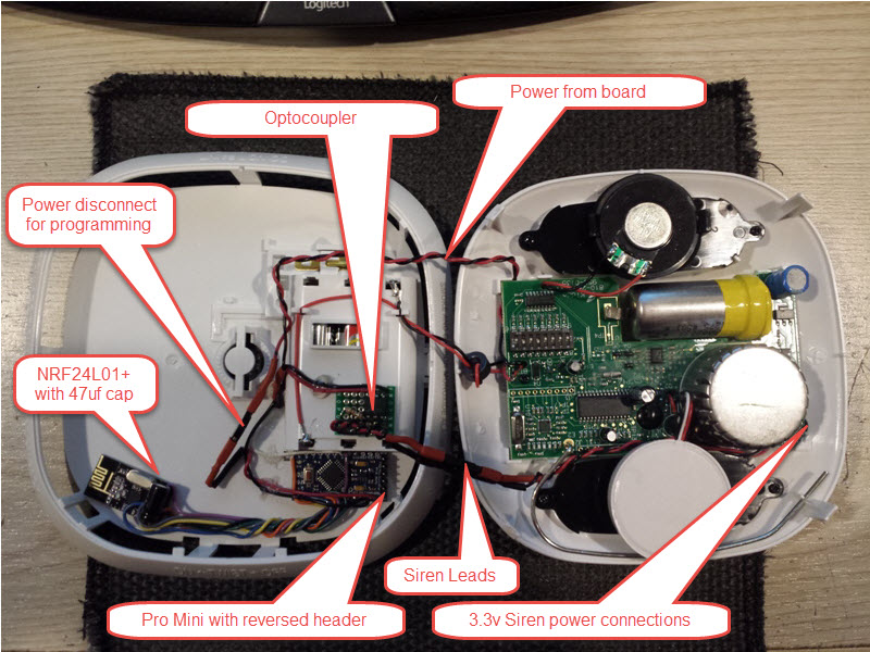
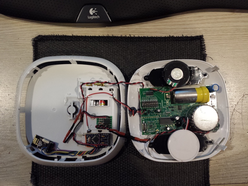
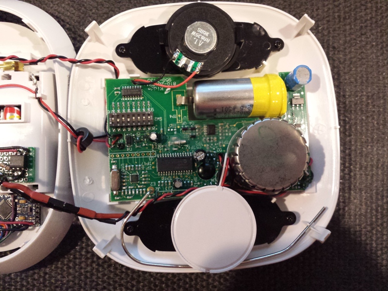
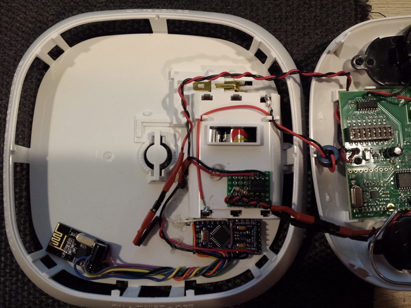
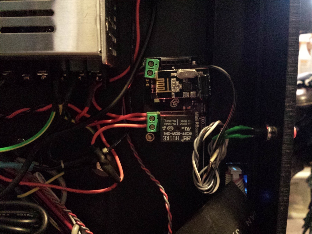
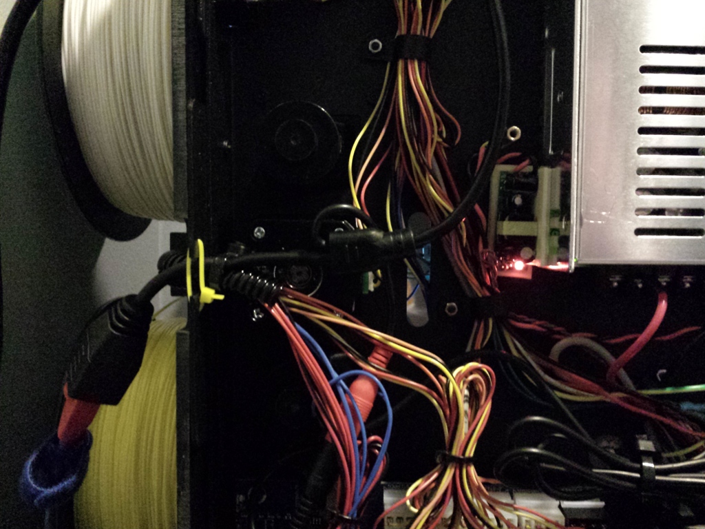
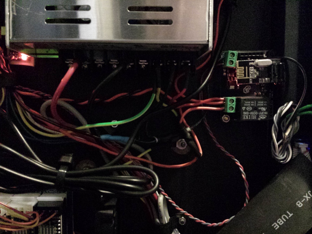
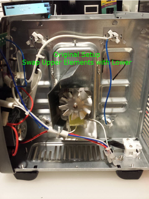
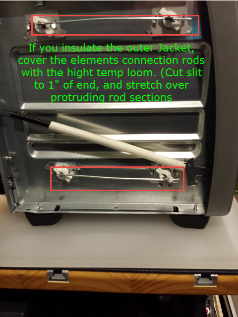
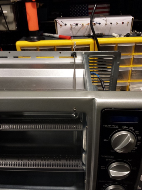
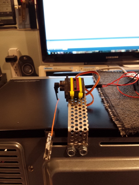
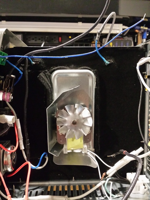
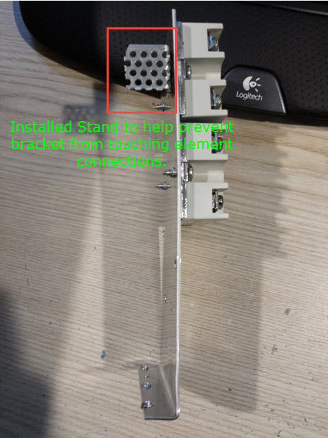
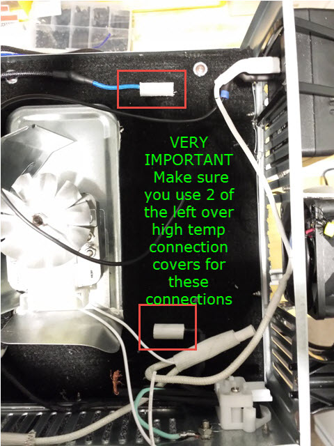
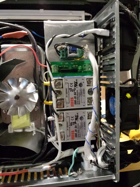
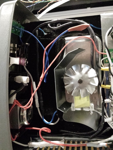
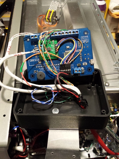
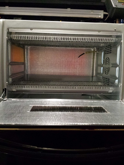
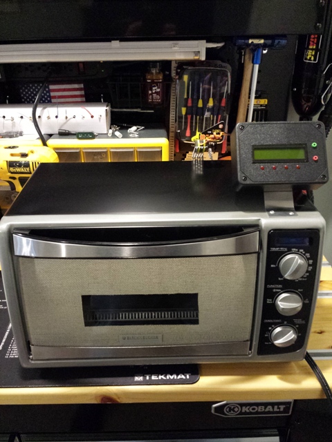
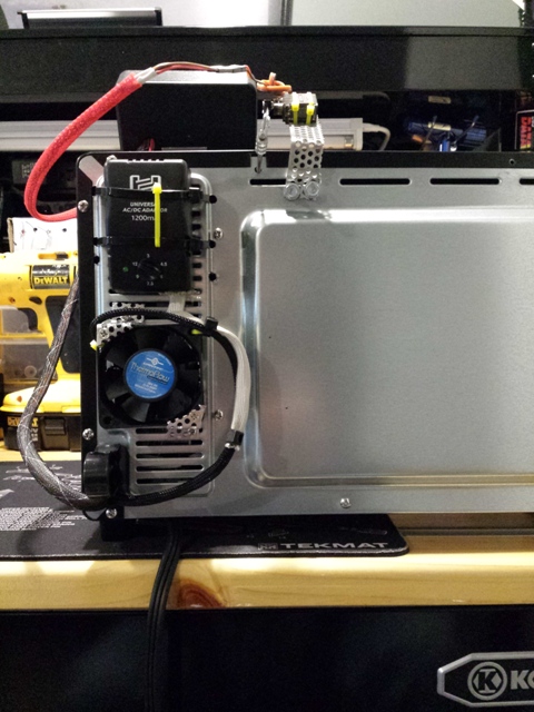
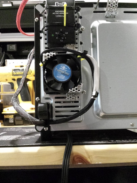
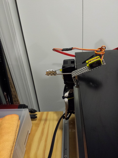
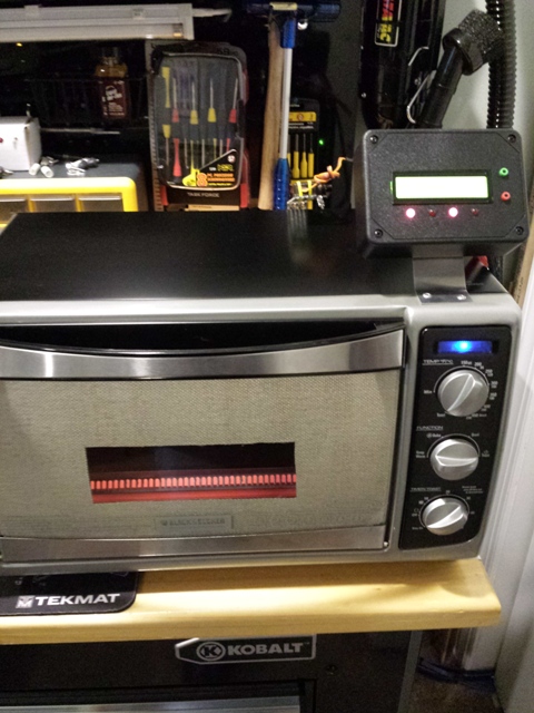
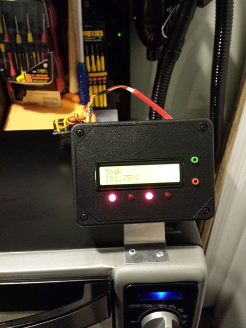
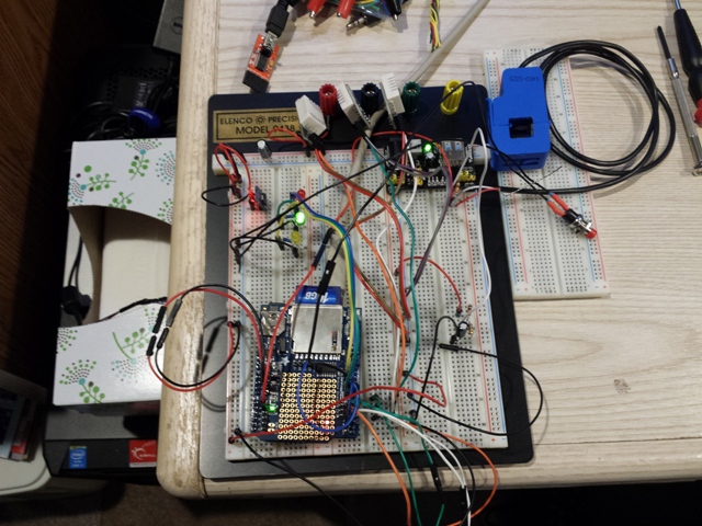
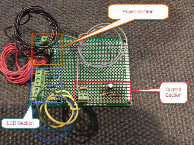
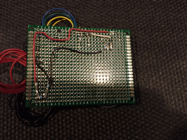
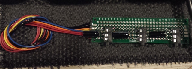
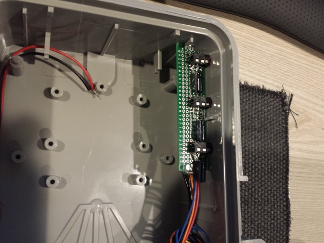
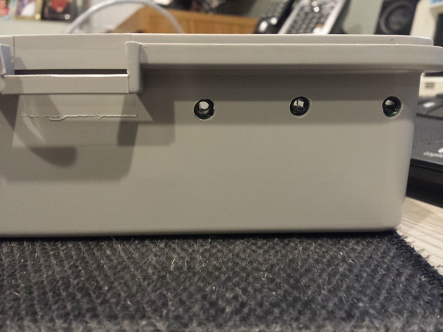
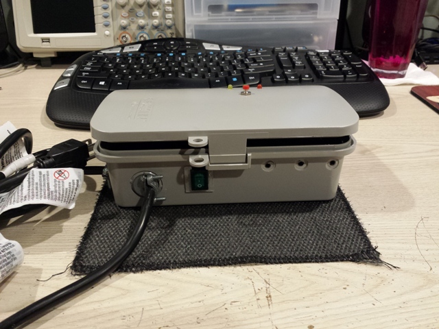
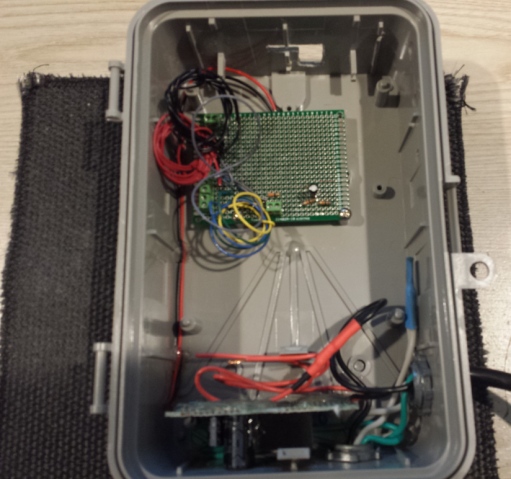
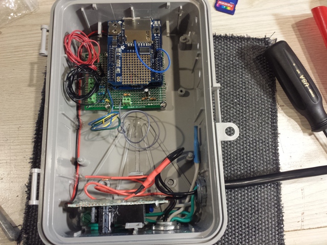
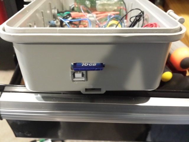
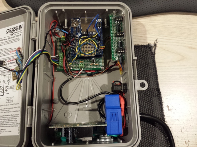
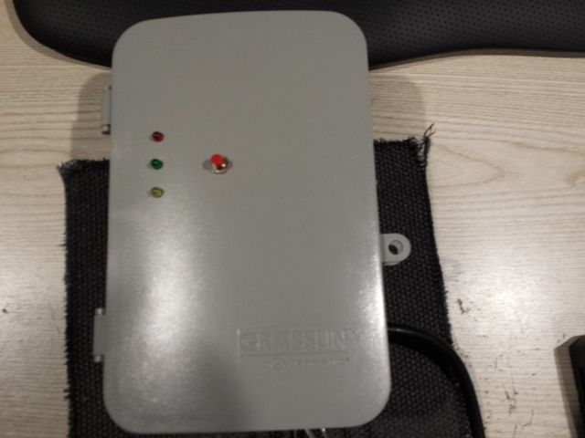
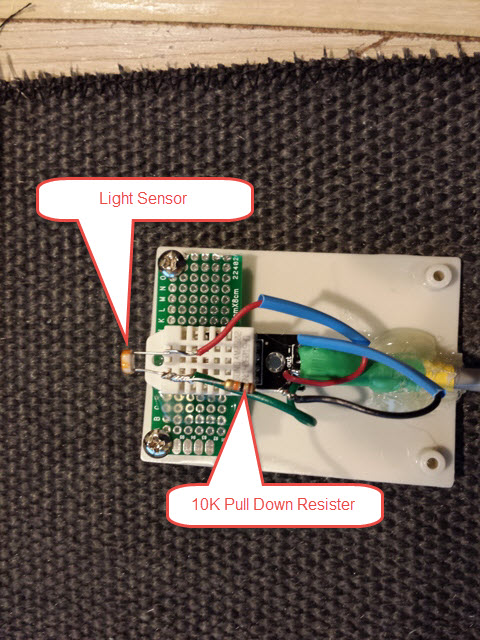
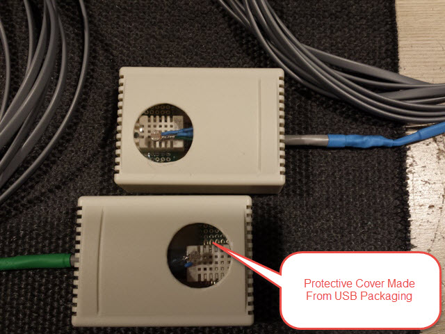
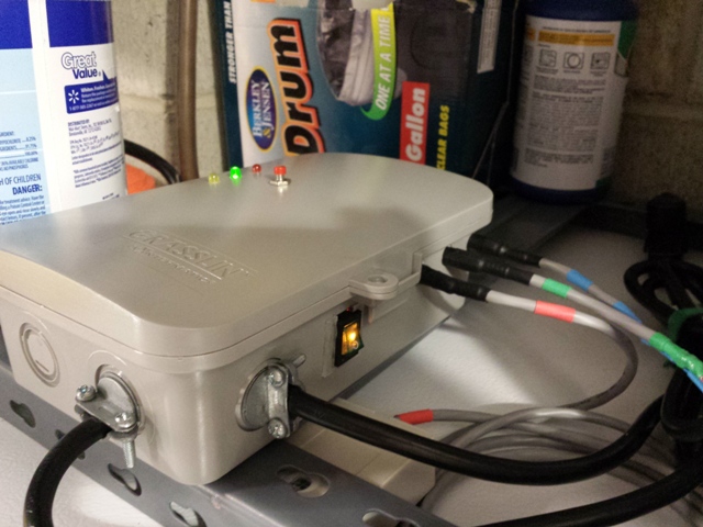
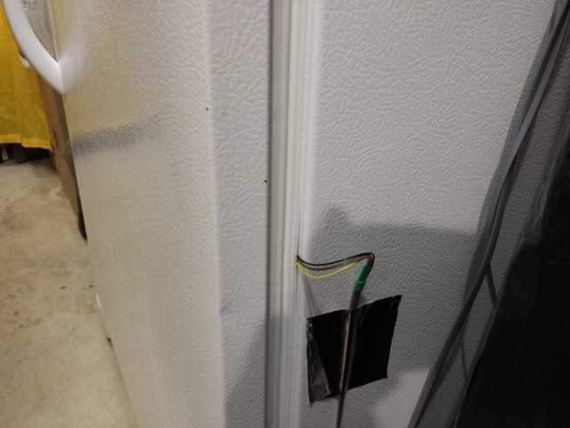
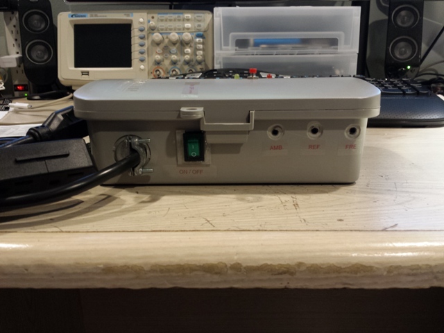
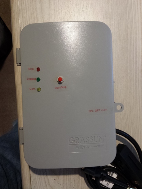
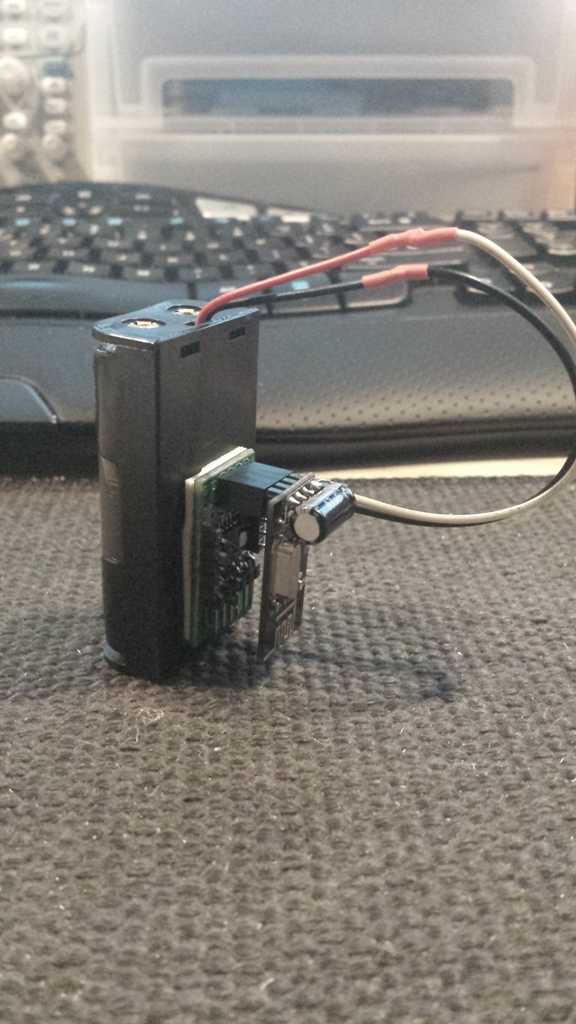
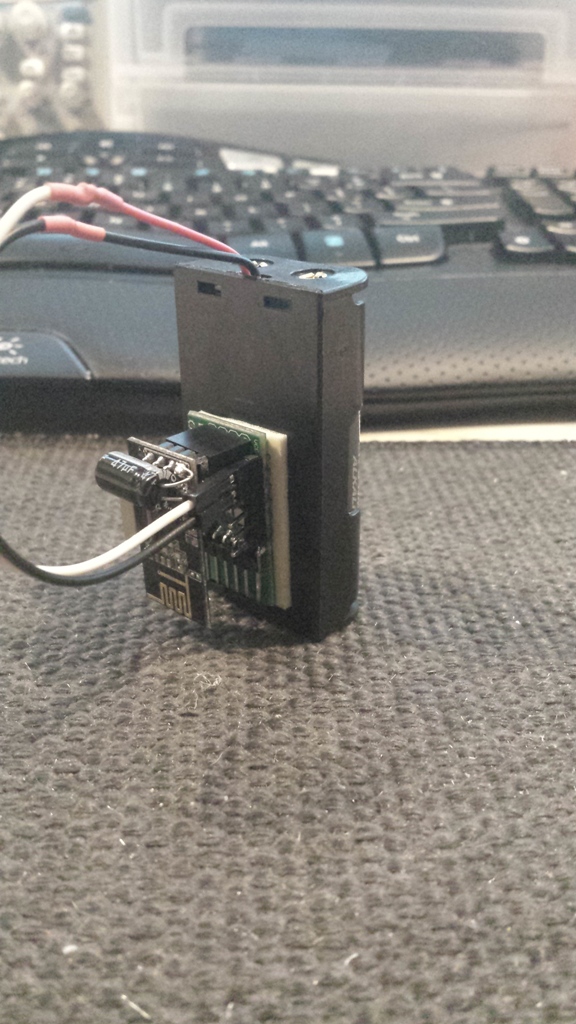
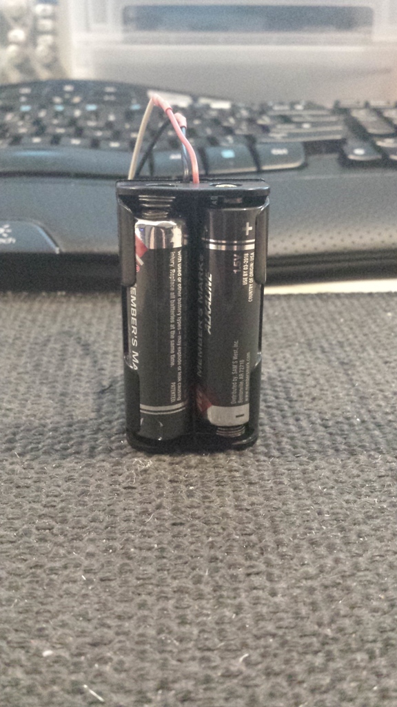
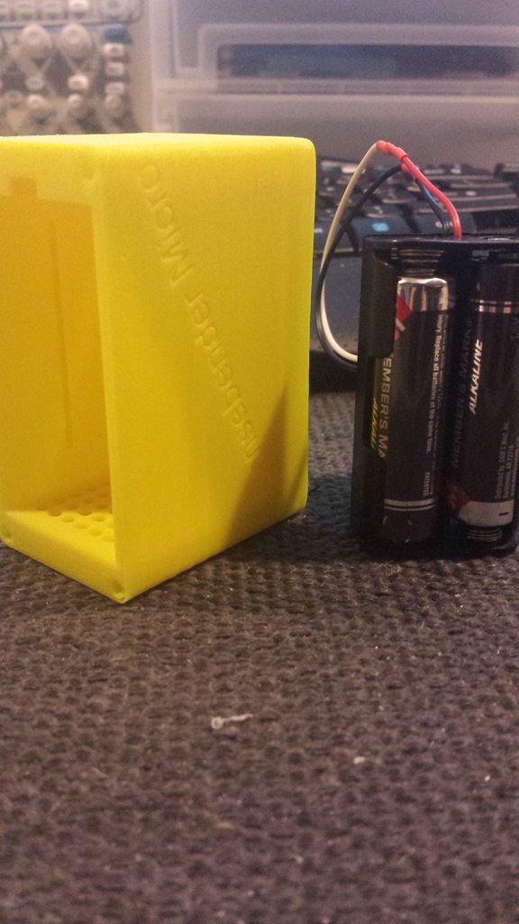
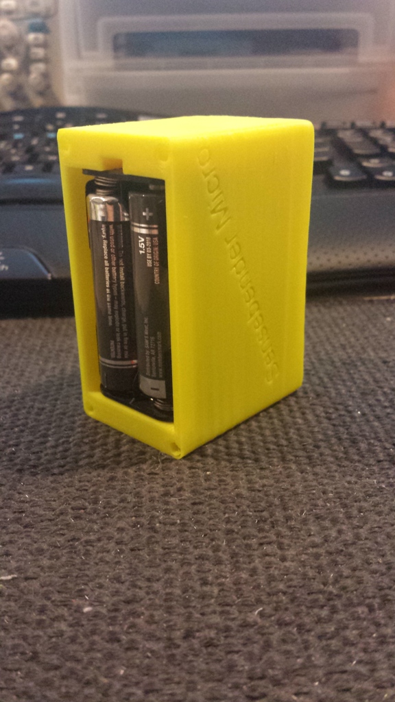
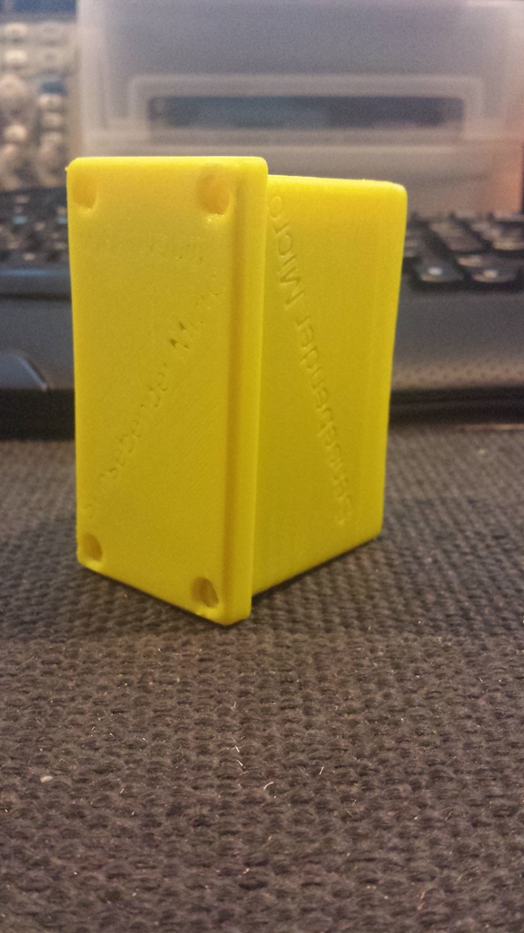
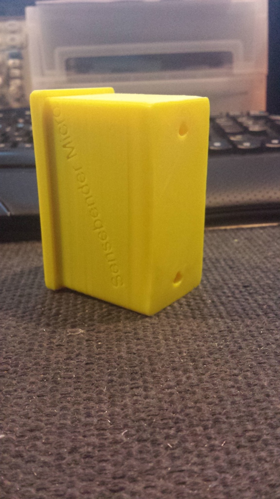
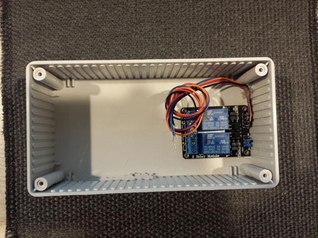
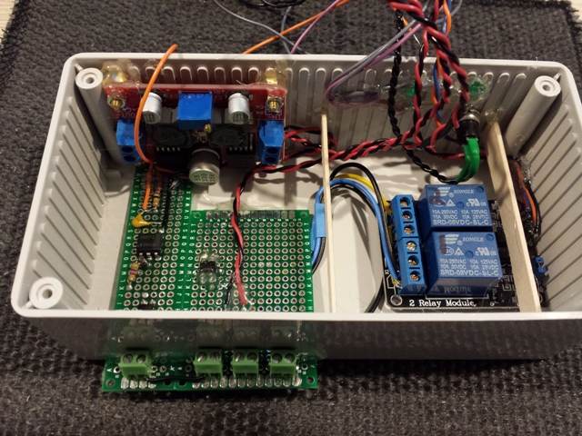
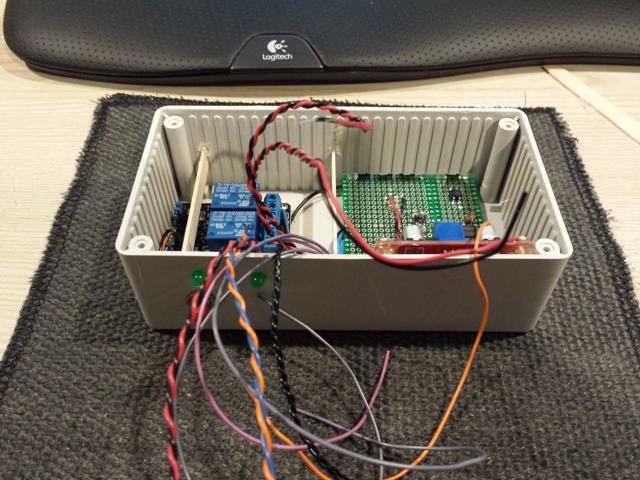
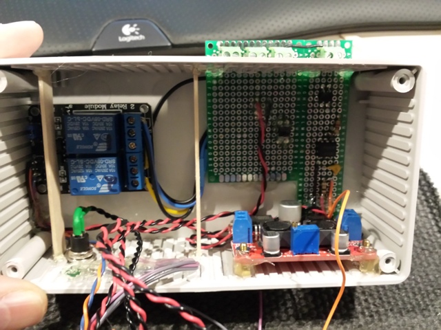
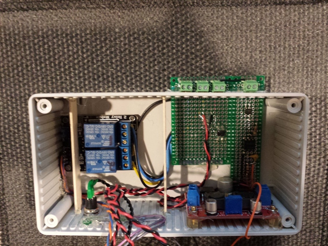
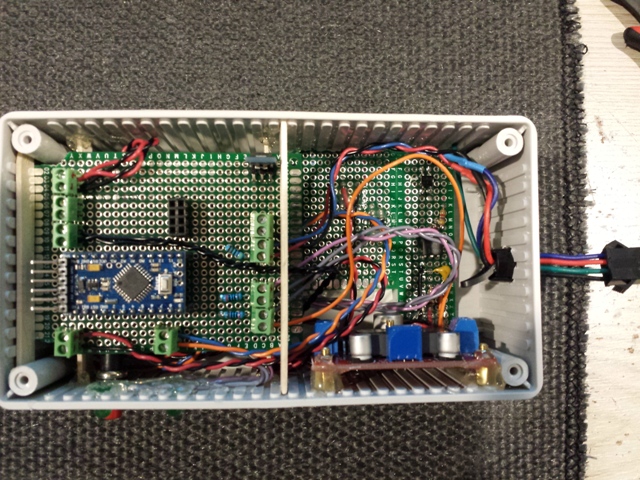
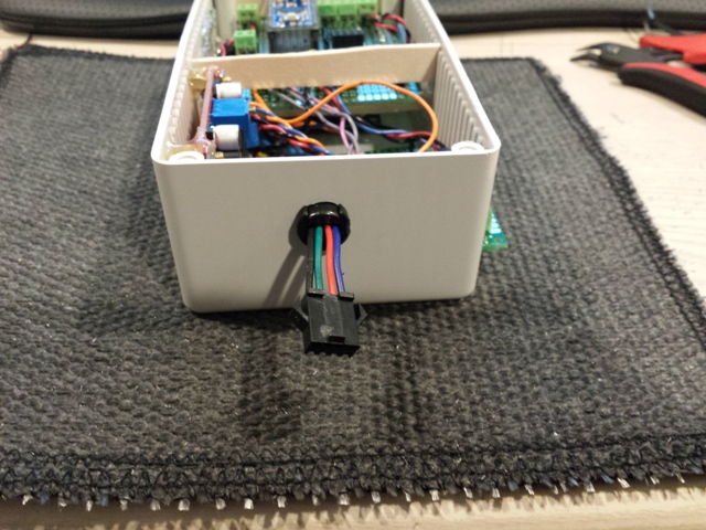
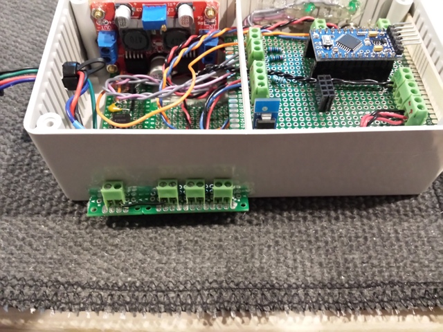
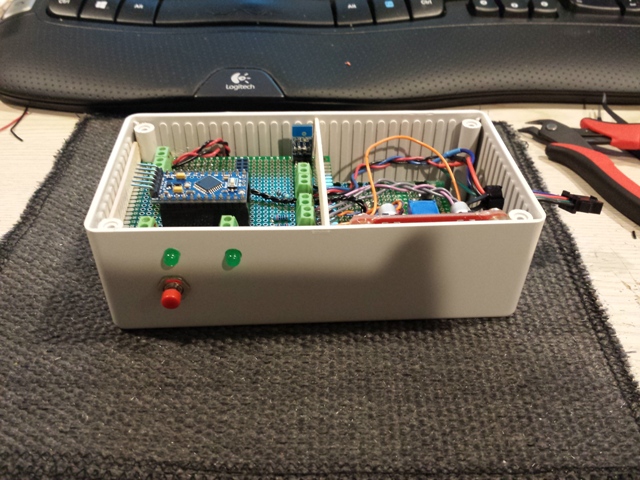
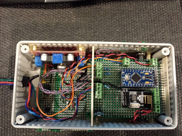
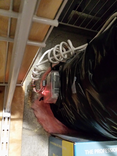
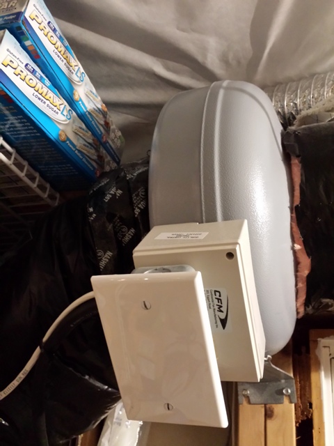
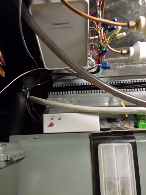
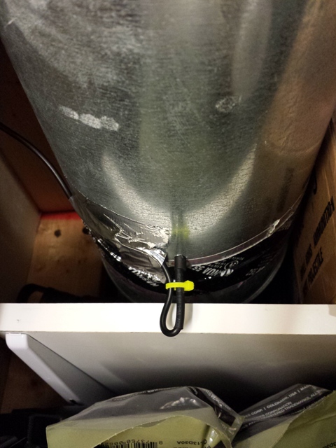
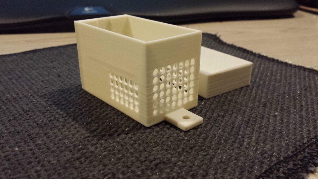
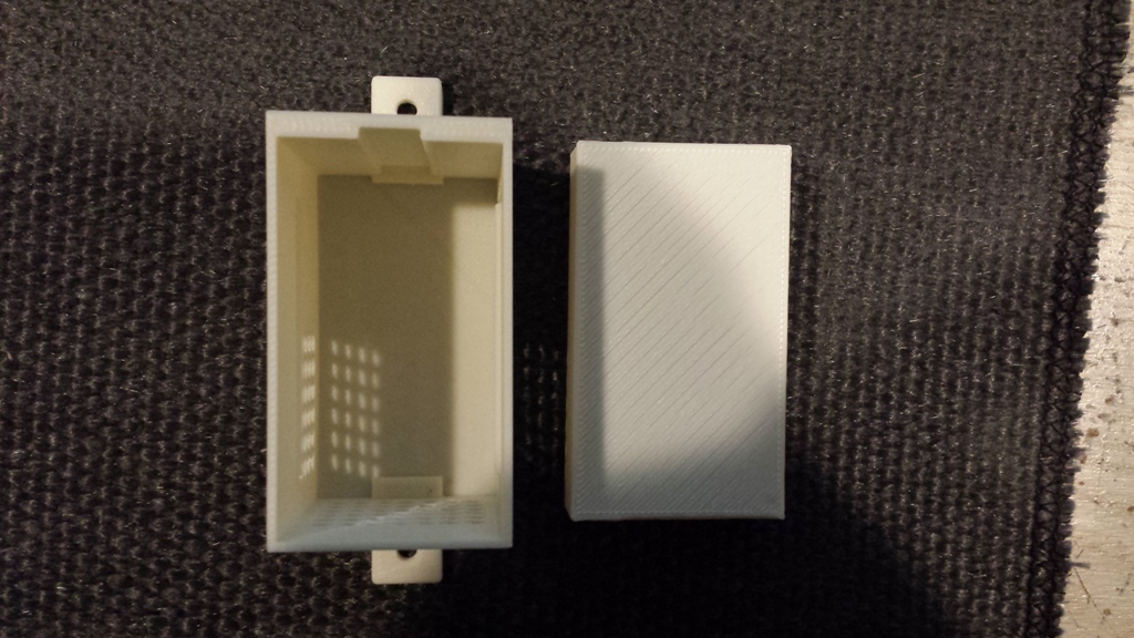
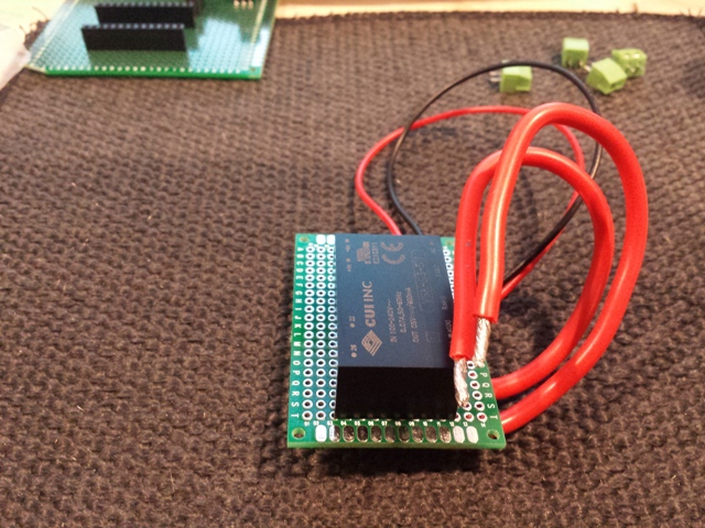
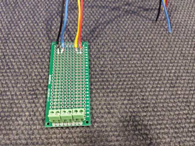
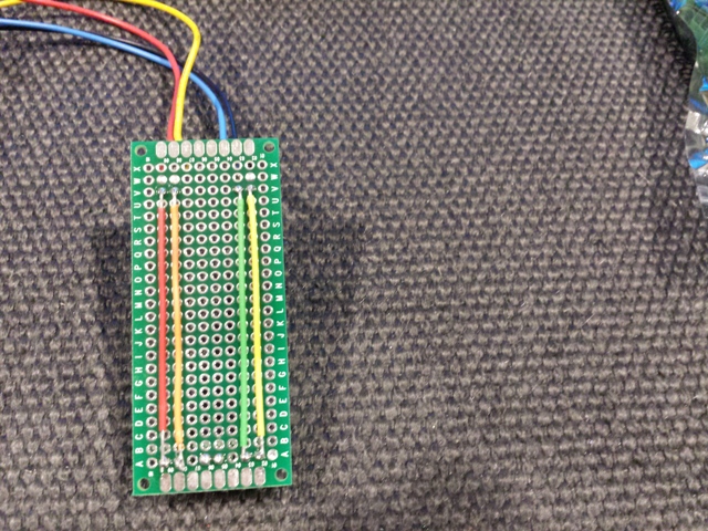
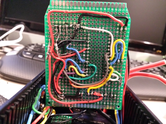
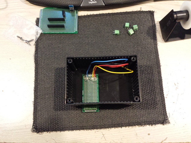
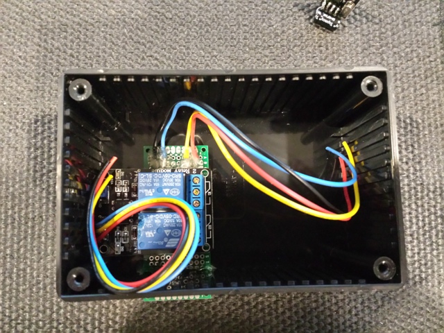
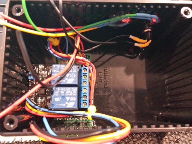
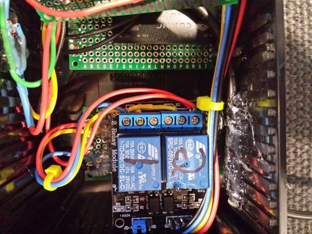
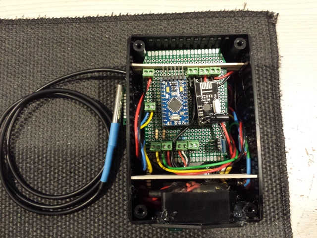
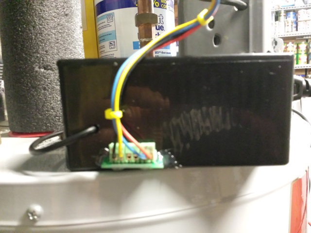
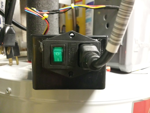
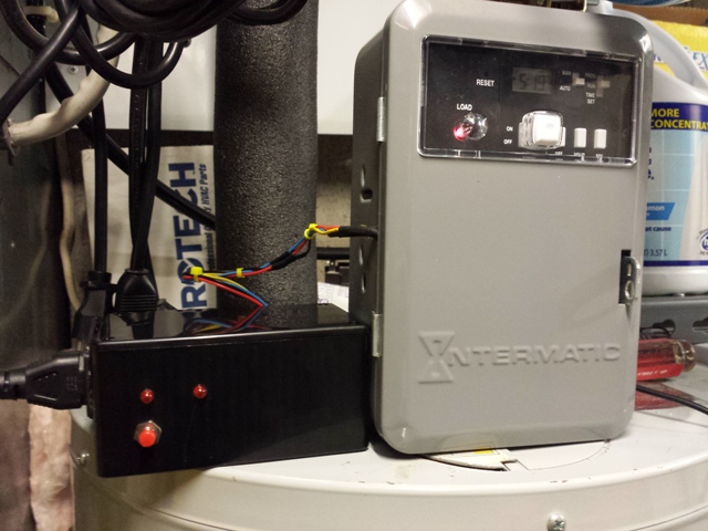
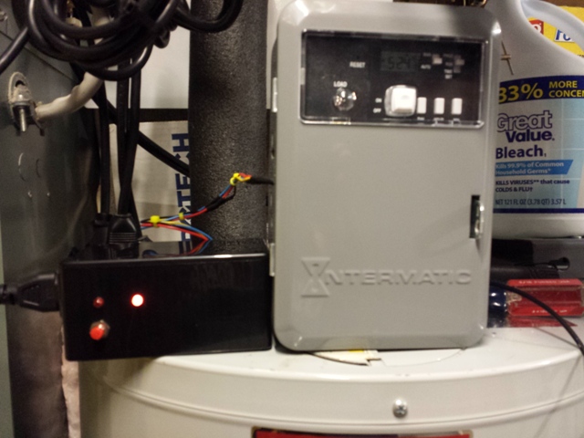
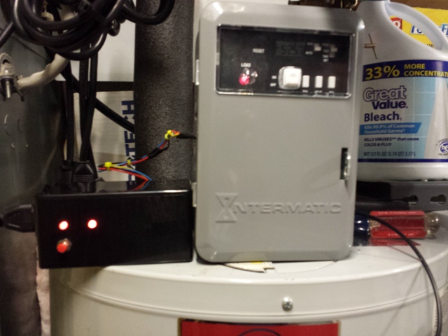
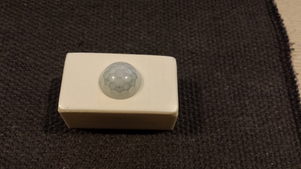
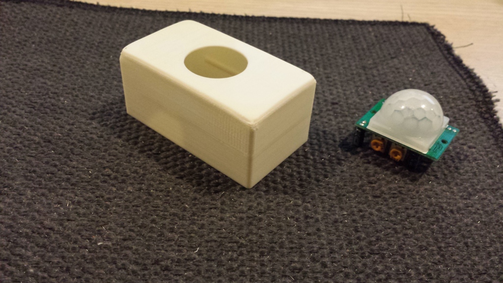
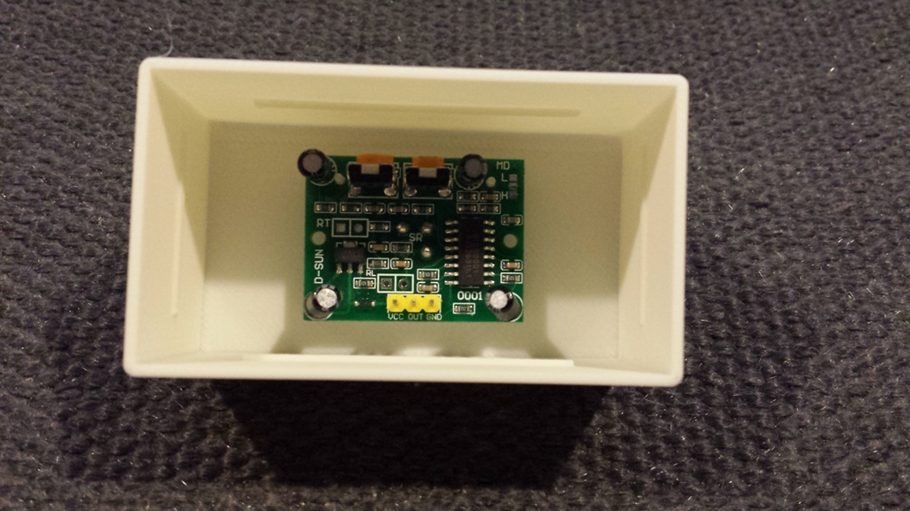
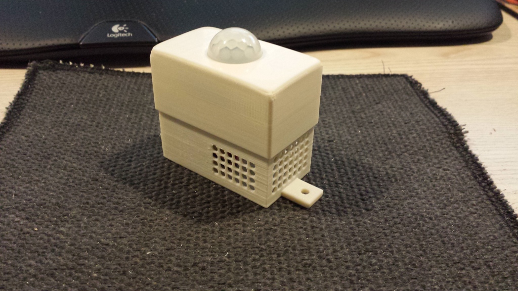
Here a some Pictures: