Navigation

    • Register
    • Login
    • OpenHardware.io
    • Categories
    • Recent
    • Tags
    • Popular
    1. Home
    2. romeo01
    3. Posts
    • Profile
    • Following
    • Followers
    • Topics
    • Posts
    • Best
    • Groups

    Posts made by romeo01

    • RE: Consumption & idle Loop

      Hi Yveaux, many thanks for your effort to my case.

      I didn't knew that after a wakeup, nrf24 is in stby before the next restart loop.
      Indeed, I tried a new sketch and confirm this particularity.

      So, a workaround should be to put a "sleep()" at start of the "loop"

      void loop()
      {
      
        // => At this point NRF is in RX mode
      
        sleep(xxx ms); // Put NRF24 in stby
      
       // ******
       //
       // All job here without NRF consumption !!
       //
       // *****
      
      } // End of loop


      I will do something like that !!

      Maybe, a new definition should be interresting, like MY_NRF24_RXMODE_DISABLED

      I'm sure many nodes never need the RX mode.

      PS: Hum.. !! I didn't tried if after the send command, NRF24 come back in RX mode or not.

      posted in Development
      romeo01
      romeo01
    • RE: Consumption & idle Loop

      In my case, node is awake every 5 minutes for a couple of measure (no data sent).
      An average from previous measure is only sent once by hour.
      Sometimes, awake by interrups or for monitoring some sensors.
      Most of time, no need to sent data.

      In summary, in some case, a node can be awake and doesn't send anything.
      NRF24 is still there in RX for pumping some power.

      posted in Development
      romeo01
      romeo01
    • RE: Consumption & idle Loop

      @Nca78
      Tnx fer your suggestion.

      @Yveaux
      Many low power node (running on batteries) don't need to be in RX mode.
      Like temp, door contact sensor, .....
      These simplest node only send datas.

      Is this idea could be related to a passive node ? with the RX disabled ?
      MY_PASSIVE_NODE

      posted in Development
      romeo01
      romeo01
    • RE: Consumption & idle Loop

      @yveaux Tnx fer fast reply.

      Is there there any way to put the radio in standby (no TX, no RX) when node is active ?

      posted in Development
      romeo01
      romeo01
    • RE: Consumption & idle Loop

      @mfalkvidd The problem is not here.
      In deep sleep mode, the consumption is arround 4, 5 Ua. That's perfect !

      When the node does not sleep, the NRF24 is always in RX mode.
      According to the datasheet, this one consumes +/- 12mA.

      The right question is: How to prevent the NRF24 to be in RX mode when nodes wakes up ??

      void loop{
      
      /*
       *
       *consumption here +/- 15mA
       *
       */
      
      sleep(100000) ;  // when performed , consumption +/- 4uA
      
      /*
       *
       *Immediately after wake up, consumption +/-15mA
        because NRF24 come back to RX mode.
       *
       */
      
      }
      

      I reminder, I'm looking for ultra low power node.
      My node needs only to test some input data and then send it to the Gateway.
      It never needs to RX anything from Gateway.

      I would like that NRF24 consumes only when the "send" command is performed

      send(MyMessage.set(anyData));
      

      How to put the NRF24 in sleep mode immediately after the "send command ?

      posted in Development
      romeo01
      romeo01
    • Consumption & idle Loop

      HI,

      I use a arduino pro mini 3.3v as a low power node (without power regulator and led) with a NRF24 and the lib v2.3.0-alpha

      In deep sleep mode, the consumption is arround 4, 5 Ua. That's perfect !

      Why the consumption is arround 15mA, with the sketch below. ??

      #define MY_RADIO_RF24                     // Enable and select radio type attached
      
      #define MY_RF24_PA_LEVEL RF24_PA_MAX
      
      #define MY_NODE_ID 250
      #define MY_PARENT_NODE_ID 0       
      #define MY_PARENT_NODE_IS_STATIC
      
      #define MY_BAUD_RATE 9600
                  
      #include <MySensors.h>
      
      void setup() { }
      
      void presentation(){ 
      
            sendSketchInfo("Dummy Node", "1.0");
      
      }
      
      void loop() { }
      

      This sketch does nothing as you can see, the Loop{} is empty BUT consumes 15mA at full time.
      That's just for test purpose.

      When it's running, if I unplug the NRF24, the consumption go down to few mA ( 2, 3 mA)

      So, I could say that every time the node wake up, NRF24 pumps the power for nothing.

      Why such consumption for a NRF24 in RX (I suppose) ?

      Afterwards, I tried to use the IRQ feature with MY_RX_MESSAGE_BUFFER_FEATURE and
      MY_RF24_IRQ_PIN

      but same consumption, not less than 15mA with an empty Loop.

      In my case, I don't need to receive anything from the gateway after the registration. Can I stop the "receive mode" for a NRF24 ??
      I just need to send a couple of data and then go to sleep.
      The RX period is a waste of energy.

      Any idea ?? Thanks

      posted in Development
      romeo01
      romeo01
    • RE: 💬 Building a Raspberry Pi Gateway

      @mfalkvidd Thanks fer info, now I can see the serial protocol as well in the syslog. Next step should be to have a logfile dedicated to mysgw.

      posted in Announcements
      romeo01
      romeo01
    • RE: 💬 Building a Raspberry Pi Gateway

      How can I monitor the traffic data between the raspberry and RF module (NRF24L01) on a Ethernet gateway ??

      My gateway is built for Ethernet. I start the gateway with "service mysgw start"
      Now, I would like to get the same data output than output debug (./bin/mysgw -d) but without stop mysgw service.
      I need to use MYSController as Ethernet client at the same time.

      Thanks

      posted in Announcements
      romeo01
      romeo01
    • I_LOG_MESSAGE & OTALogPrint()

      I try to send a C_INTERNAL / I_LOG_MESSAGE via MYSController.

      According to the documentation, that's the same output format that the OTALog() function https://www.mysensors.org/apidocs-beta/group__MyOTALogginggrp.html

      That's what I send "100;255;3;0;9;Hello"
      from MYSController via a raspberry Gateway (2.2.0-rc.2) to NodeID: 100

      On the node receiver: (ID #100) VER=2.2.0-rc.2
      // Enable OTA log display
      #define MY_OTA_LOG_RECEIVER_FEATURE

      I got the message below on the serial output

      157866 TSF:MSG:READ,0-0-100,s=0,c=3,t=9,pt=0,l=5,sg=0:Hello
      ⸮⸮⸮WvqA⸮⸮⸮⸮⸮⸮⸮⸮;⸮⸮In⸮⸮r⸮⸮i⸮Og⸮⸮Hello...
      

      The message is unreadable as you can see.
      What's wrong ??

      I have the same issue with LogOTANode & LogOTAGateway sketch examples. That doesn't work.
      Something seems to be wrong arround OTALogPrint() function
      https://www.mysensors.org/apidocs-beta/group__MyOTALogginggrp.html#gacda87d62975a29d2a379ce2ac64bab26

      My goal is to send some debug messages from a node to another one. I need to check and see what's happening in my sketch in development version. The node is inaccessible.

      posted in Development
      romeo01
      romeo01
    • LogOTANode & LogOTAGateway

      Hi All,

      Someone could confirm me that LogOTANode & LogOTAGateway sketch example work correctly.

      I'm unable to test the OTA degug feature because all characters sent by the node are unreadeable.

      In fact, I do not try with the logOTAGateway sketch, because I aready have a gateway running. But I use a new node with unique ID to receive all debug messages from the fist node (LogOTANode).

      TX_LogOTANode.ino (TX OTA)

      /**
       * The MySensors Arduino library handles the wireless radio link and protocol
       * between your home built sensors/actuators and HA controller of choice.
       * The sensors forms a self healing radio network with optional repeaters. Each
       * repeater and gateway builds a routing tables in EEPROM which keeps track of the
       * network topology allowing messages to be routed to nodes.
       *
       * Created by Henrik Ekblad <henrik.ekblad@mysensors.org>
       * Copyright (C) 2013-2015 Sensnology AB
       * Full contributor list: https://github.com/mysensors/Arduino/graphs/contributors
       *
       * Documentation: http://www.mysensors.org
       * Support Forum: http://forum.mysensors.org
       *
       * This program is free software; you can redistribute it and/or
       * modify it under the terms of the GNU General Public License
       * version 2 as published by the Free Software Foundation.
       *
       *******************************
       *
       * DESCRIPTION
       *
       * Example for sending debug messages over the air (OTA).
       *
       */


      // Enable debug
      #define MY_DEBUG
      
      // Enable OTA debugging to Node 100
      #define MY_DEBUG_OTA (100)
      
      // Allow sending logs without MY_DEBUG_OTA enabled
      #define MY_OTA_LOG_SENDER_FEATURE
      
      #define MY_NODE_ID 50
      
      
      // Disable ACK for debug messages
      //#define MY_DEBUG_OTA_DISABLE_ACK
      
      // Enable and select radio type attached
      #define MY_RADIO_NRF24
      
      #include <MySensors.h>
      
      void setup()
      {
      }
      
      void presentation()
      {
        // Send the sketch version information to the gateway and Controller
        sendSketchInfo("TX DebugSensor", "1.0");
      }
      
      // Arduino loop
      int c=0;
      void loop()
      {
        // Wait some time
        if (sleep(3000)==MY_SLEEP_NOT_POSSIBLE) {
          delay(3000);
        }
      
        // Count loops
        c++;
      
        // A debug message
        DEBUG_OUTPUT(PSTR("DEBUG\nc=%" PRId16 "\nmillis=%" PRId32 "\n"), c, hwMillis());
      
        // Send a log message with ACK to a node
        OTALog(100, true, PSTR("LOG\nc=%" PRId16 "\nmillis=%" PRId32 "\n"), c, hwMillis() );


      }
      

      RX_LogOTANode.ino (RX OTA)

      /**
      * The MySensors Arduino library handles the wireless radio link and protocol
      * between your home built sensors/actuators and HA controller of choice.
      * The sensors forms a self healing radio network with optional repeaters. Each
      * repeater and gateway builds a routing tables in EEPROM which keeps track of the
      * network topology allowing messages to be routed to nodes.
      *
      * Created by Henrik Ekblad <henrik.ekblad@mysensors.org>
      * Copyright (C) 2013-2015 Sensnology AB
      * Full contributor list: https://github.com/mysensors/Arduino/graphs/contributors
      *
      * Documentation: http://www.mysensors.org
      * Support Forum: http://forum.mysensors.org
      *
      * This program is free software; you can redistribute it and/or
      * modify it under the terms of the GNU General Public License
      * version 2 as published by the Free Software Foundation.
      *
      */
      
      // Enable debug prints to serial monitor
      #define MY_DEBUG
      
      // Enable OTA log display
      #define MY_OTA_LOG_RECEIVER_FEATURE
      
      #define MY_NODE_ID 100
      
      
      // Enable and select radio type attached
      #define MY_RADIO_NRF24
      
      #define MY_BAUD_RATE 115200
      
      #include <MySensors.h>
      
      void setup()
      {
        // Setup locally attached sensors
      }
      
      void presentation()
      {
          sendSketchInfo("RX DEBUG Display", "1.0");
      
      }
      
      void loop()
      {
        // Send locally attached sensor data here
      }


      // Traite les messages provenant de la Gateway
      void receive(const MyMessage &message){
      
        OTALogPrint(message);
        
      }


      Pse confirm if the sketchs above are OK and run on your side.
      Thanks in advance.

      posted in Development
      romeo01
      romeo01
    • RE: 💬 Building a Raspberry Pi Gateway

      Exactly, but I would like to use the gateway (raspberry) as target.
      Is that possible ?
      If yes, how to display the debug message on the gateway.
      I have an access to my gateway only via SSH.

      posted in Announcements
      romeo01
      romeo01
    • RE: 💬 Building a Raspberry Pi Gateway

      @gohan said in 💬 Building a Raspberry Pi Gateway:

      @romeo01 said in 💬 Building a Raspberry Pi Gateway:

      MY_DEBUG_OTA

      I'd start reading from here https://www.mysensors.org/apidocs-beta/group__SerialDebugGrpPub.html#ga6bd5956352d3a184a0cb02783b8d35ff

      Well, you found the starting point !

      MY_OTA_LOG_SENDER_FEATURE & MY_DEBUG_OTA are enabled on my OTA node.

      Again the same question: What I have to do on the gateway side ?
      Is it possible with the raspberry Gateway ?

      I'm still looking for debugging my sketch in remote. I need to have a look on the debug messages. I reminder, the node is not accessible and runs MYSbootloader.

      posted in Announcements
      romeo01
      romeo01
    • RE: 💬 Building a Raspberry Pi Gateway

      In fact, I do not need to log, but need to look what's happen in my sketch.
      The new "OTALog" function, MY_OTA_LOG_SENDER_FEATURE or MY_DEBUG_OTA seems to be the good way.
      From the docs, it allows to send a debug message to another node or gateway via OTA.

      But how to got the debug message from OTA node, on the gateway side (RaspberryPi) ?

      posted in Announcements
      romeo01
      romeo01
    • RE: 💬 Building a Raspberry Pi Gateway

      Can we use the "debug ota log" features with the raspberryPi gateway ??

      My node is not accessible and runs MYSBootloader.
      My gateway is raspberryPI.

      Now, I need to update the firmware on my node. Via MYSController, no problems, upload runs like a charm.

      But how to do for debugging my sketch ? Some bugs appear...... , I need to take a look on some vars values.
      Usually, I use the serial port with serial.print(some vars).
      Which alternative I have to use without serial port, only OTA features ?

      Thanks for the great work !!

      posted in Announcements
      romeo01
      romeo01
    • RE: Windows GUI/Controller for MySensors

      With MSController 1.0.0 & SerialGateway with 2.2.0 MySensor lib, 1 problem occurs.

      MSController crash at the presentation step by the node

      Below what the node send when reeboot. (Debug log via Serial)

      0 MCO:BGN:INIT NODE,CP=RNNNA---,VER=2.2.0-beta
      26 TSM:INIT
      27 TSF:WUR:MS=0
      34 TSM:INIT:TSP OK
      35 TSM:INIT:STATID=1
      37 TSF:SID:OK,ID=1
      39 TSM:FPAR
      75 TSF:MSG:SEND,1-1-255-255,s=255,c=3,t=7,pt=0,l=0,sg=0,ft=0,st=OK:
      1051 TSF:MSG:READ,0-0-1,s=255,c=3,t=8,pt=1,l=1,sg=0:0
      1056 TSF:MSG:FPAR OK,ID=0,D=1
      2083 TSM:FPAR:OK
      2084 TSM:ID
      2085 TSM:ID:OK
      2087 TSM:UPL
      2091 TSF:MSG:SEND,1-1-0-0,s=255,c=3,t=24,pt=1,l=1,sg=0,ft=0,st=OK:1
      2101 TSF:MSG:READ,0-0-1,s=255,c=3,t=25,pt=1,l=1,sg=0:1
      2106 TSF:MSG:PONG RECV,HP=1
      2109 TSM:UPL:OK
      2110 TSM:READY:ID=1,PAR=0,DIS=1
      2115 TSF:MSG:SEND,1-1-0-0,s=255,c=3,t=15,pt=6,l=2,sg=0,ft=0,st=OK:0100
      2122 TSF:MSG:READ,0-0-1,s=255,c=3,t=15,pt=6,l=2,sg=0:0100
      2129 TSF:MSG:SEND,1-1-0-0,s=255,c=0,t=17,pt=0,l=10,sg=0,ft=0,st=OK:2.2.0-beta
      2139 TSF:MSG:SEND,1-1-0-0,s=255,c=3,t=6,pt=1,l=1,sg=0,ft=0,st=OK:0
      2155 TSF:MSG:READ,0-0-1,s=255,c=3,t=6,pt=0,l=1,sg=0:M
      2162 TSF:MSG:SEND,1-1-0-0,s=255,c=3,t=11,pt=0,l=10,sg=0,ft=0,st=OK:OTA Test 2
      2171 TSF:MSG:SEND,1-1-0-0,s=255,c=3,t=12,pt=0,l=3,sg=0,ft=0,st=OK:2.0
      2180 TSF:MSG:SEND,1-1-0-0,s=1,c=0,t=3,pt=0,l=8,sg=0,ft=0,st=OK:Sensor 1
      2187 MCO:REG:REQ
      2190 TSF:MSG:SEND,1-1-0-0,s=255,c=3,t=26,pt=1,l=1,sg=0,ft=0,st=OK:2
      2197 TSF:MSG:READ,0-0-1,s=255,c=3,t=27,pt=1,l=1,sg=0:1
      2202 MCO:PIM:NODE REG=1
      2204 MCO:BGN:STP
      2205 MCO:BGN:INIT OK,TSP=1
      

      Below is the log in MSController

      08/05/2017 18:12:26	RX	0;255;3;0;9;33925 TSF:MSG:READ,1-1-255,s=255,c=3,t=7,pt=1,l=1,sg=0:0
      08/05/2017 18:12:26	RX	0;255;3;0;9;33931 TSF:MSG:BC
      08/05/2017 18:12:26	RX	0;255;3;0;9;33933 TSF:MSG:FPAR REQ,ID=1
      08/05/2017 18:12:26	RX	0;255;3;0;9;33937 TSF:PNG:SEND,TO=0
      08/05/2017 18:12:26	RX	0;255;3;0;9;33940 TSF:CKU:OK
      08/05/2017 18:12:26	RX	0;255;3;0;9;33943 TSF:MSG:GWL OK
      08/05/2017 18:12:26	RX	0;255;3;0;9;34102 TSF:MSG:SEND,0-0-1-1,s=255,c=3,t=8,pt=1,l=1,sg=0,ft=0,st=OK:0
      08/05/2017 18:12:29	RX	0;255;3;0;9;37248 TSF:MSG:READ,1-1-255,s=255,c=3,t=7,pt=1,l=1,sg=0:0
      08/05/2017 18:12:29	RX	0;255;3;0;9;37254 TSF:MSG:BC
      08/05/2017 18:12:29	RX	0;255;3;0;9;37257 TSF:MSG:FPAR REQ,ID=1
      08/05/2017 18:12:29	RX	0;255;3;0;9;37260 TSF:CKU:OK,FCTRL
      08/05/2017 18:12:29	RX	0;255;3;0;9;37263 TSF:MSG:GWL OK
      08/05/2017 18:12:30	RX	0;255;3;0;9;37669 TSF:MSG:SEND,0-0-1-1,s=255,c=3,t=8,pt=1,l=1,sg=0,ft=0,st=OK:0
      08/05/2017 18:12:32	RX	0;255;3;0;9;40570 TSF:MSG:READ,1-1-0,s=255,c=3,t=15,pt=6,l=2,sg=0:0100
      08/05/2017 18:12:32	RX	0;255;3;0;9;40579 TSF:MSG:SEND,0-0-1-1,s=255,c=3,t=15,pt=6,l=2,sg=0,ft=0,st=OK:0100
      08/05/2017 18:12:33	RX	0;255;3;0;9;40729 TSF:MSG:READ,1-1-0,s=255,c=4,t=0,pt=6,l=10,sg=0:28000100E803E5750103
      08/05/2017 18:12:33	RX	1;255;4;0;0;28000100E803E5750103
      08/05/2017 18:12:33	INFO	BL version=259
      08/05/2017 18:12:33	INFO	No FW assigned
      08/05/2017 18:12:36	RX	0;255;3;0;9;44053 TSF:MSG:READ,1-1-0,s=255,c=4,t=0,pt=6,l=10,sg=0:28000100E803E5750103
      08/05/2017 18:12:36	RX	1;255;4;0;0;28000100E803E5750103
      08/05/2017 18:12:36	INFO	BL version=259
      08/05/2017 18:12:36	INFO	No FW assigned
      08/05/2017 18:12:39	RX	0;255;3;0;9;47376 TSF:MSG:READ,1-1-0,s=255,c=4,t=0,pt=6,l=10,sg=0:28000100E803E5750103
      08/05/2017 18:12:39	RX	1;255;4;0;0;28000100E803E5750103
      08/05/2017 18:12:39	INFO	BL version=259
      08/05/2017 18:12:39	INFO	No FW assigned
      08/05/2017 18:12:43	RX	0;255;3;0;9;50700 TSF:MSG:READ,1-1-0,s=255,c=4,t=0,pt=6,l=10,sg=0:28000100E803E5750103
      08/05/2017 18:12:43	RX	1;255;4;0;0;28000100E803E5750103
      08/05/2017 18:12:43	INFO	BL version=259
      08/05/2017 18:12:43	INFO	No FW assigned
      08/05/2017 18:12:46	RX	0;255;3;0;9;54213 TSF:MSG:READ,1-1-255,s=255,c=3,t=7,pt=0,l=0,sg=0:
      08/05/2017 18:12:46	RX	0;255;3;0;9;54219 TSF:MSG:BC
      08/05/2017 18:12:46	RX	0;255;3;0;9;54222 TSF:MSG:FPAR REQ,ID=1
      08/05/2017 18:12:46	RX	0;255;3;0;9;54226 TSF:PNG:SEND,TO=0
      08/05/2017 18:12:46	RX	0;255;3;0;9;54230 TSF:CKU:OK
      08/05/2017 18:12:46	RX	0;255;3;0;9;54232 TSF:MSG:GWL OK
      08/05/2017 18:12:47	RX	0;255;3;0;9;55224 TSF:MSG:SEND,0-0-1-1,s=255,c=3,t=8,pt=1,l=1,sg=0,ft=0,st=OK:0
      08/05/2017 18:12:48	RX	0;255;3;0;9;56261 TSF:MSG:READ,1-1-0,s=255,c=3,t=24,pt=1,l=1,sg=0:1
      08/05/2017 18:12:48	RX	0;255;3;0;9;56267 TSF:MSG:PINGED,ID=1,HP=1
      08/05/2017 18:12:48	RX	0;255;3;0;9;56273 TSF:MSG:SEND,0-0-1-1,s=255,c=3,t=25,pt=1,l=1,sg=0,ft=0,st=OK:1
      08/05/2017 18:12:48	RX	0;255;3;0;9;56286 TSF:MSG:READ,1-1-0,s=255,c=3,t=15,pt=6,l=2,sg=0:0100
      08/05/2017 18:12:48	RX	0;255;3;0;9;56294 TSF:MSG:SEND,0-0-1-1,s=255,c=3,t=15,pt=6,l=2,sg=0,ft=0,st=OK:0100
      08/05/2017 18:12:48	RX	0;255;3;0;9;56302 TSF:MSG:READ,1-1-0,s=255,c=0,t=17,pt=0,l=10,sg=0:2.2.0-beta
      08/05/2017 18:12:48	RX	1;255;0;0;17;2.2.0-beta
      08/05/2017 18:12:48	DEBUG	Update child id=255, type=S_ARDUINO_NODE
      08/05/2017 18:12:48	RX	0;255;3;0;9;56309 TSF:MSG:READ,1-1-0,s=255,c=3,t=6,pt=1,l=1,sg=0:0
      08/05/2017 18:12:48	RX	1;255;3;0;6;0
      08/05/2017 18:12:48	TX	1;255;3;0;6;M
      08/05/2017 18:12:48	RX	0;255;3;0;9;56328 TSF:MSG:SEND,0-0-1-1,s=255,c=3,t=6,pt=0,l=1,sg=0,ft=0,st=OK:M
      08/05/2017 18:12:48	RX	0;255;3;0;9;56335 TSF:MSG:READ,1-1-0,s=255,c=3,t=11,pt=0,l=10,sg=0:OTA Test 2
      08/05/2017 18:12:48	RX	1;255;3;0;11;OTA Test 2
      08/05/2017 18:12:48	RX	0;255;3;0;9;56343 TSF:MSG:READ,1-1-0,s=255,c=3,t=12,pt=0,l=3,sg=0:2.0
      08/05/2017 18:12:48	RX	1;255;3;0;12;2.0
      08/05/2017 18:12:48	RX	0;255;3;0;9;56351 TSF:MSG:READ,1-1-0,s=1,c=0,t=3,pt=0,l=8,sg=0:Sensor 1
      

      Here a screenshot when MSController crash.

      0_1494260885106_MSController.jpg

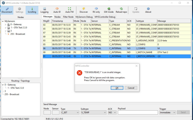
      When I click on "request presentation", same error.

      This error is only with SerialGateway & Library 2.2.0 beta
      With library 2.1.1that's ok

      posted in Controllers
      romeo01
      romeo01
    • RE: MYSBootloader 1.3 pre-release & MYSController 1.0.0beta

      Nice job, the last bootloader seems to run in good conditions.

      I use MySensors 2.2.0 beta, MYSController 1.0.0 (3314) and the last version MYSbootloader 1.3.0-beta.4 (https://github.com/mysensors/MySensorsBootloaderRF24)

      Update, flash, firmware via OTA is ok.

      But 1 problem occurs when a node reboot.
      I tried to isolate the problem, so I think that's arround the presentation request.

      When I click on "request presentation", I got it

      http://hpics.li/93e8861

      and below the debug output (via serial) of the node

      70437 TSF:MSG:READ,0-0-1,s=0,c=3,t=19,pt=0,l=1,sg=0:0
      70445 TSF:MSG:SEND,1-1-0-0,s=255,c=3,t=15,pt=6,l=2,sg=0,ft=0,st=OK:0100
      70453 TSF:MSG:READ,0-0-1,s=255,c=3,t=15,pt=6,l=2,sg=0:0100
      70460 TSF:MSG:SEND,1-1-0-0,s=255,c=0,t=17,pt=0,l=10,sg=0,ft=0,st=OK:2.2.0-beta
      70469 TSF:MSG:SEND,1-1-0-0,s=255,c=3,t=6,pt=1,l=1,sg=0,ft=0,st=OK:0
      70497 TSF:MSG:READ,0-0-1,s=255,c=3,t=6,pt=0,l=1,sg=0:M
      70504 TSF:MSG:SEND,1-1-0-0,s=255,c=3,t=11,pt=0,l=8,sg=0,ft=0,st=OK:OTA Test
      70512 TSF:MSG:SEND,1-1-0-0,s=255,c=3,t=12,pt=0,l=1,sg=0,ft=0,st=OK:1
      70521 TSF:MSG:SEND,1-1-0-0,s=1,c=0,t=3,pt=0,l=8,sg=0,ft=0,st=OK:Sensor 1
      

      Maybe a bug or where is the mistake ?

      Thanks in advance foryour help

      Edit: After a couple of test, the problem is related to the gateway with MySensor Library version 2.2.0 beta.
      All nodes (2.1.1 & 2.2.0 libs) from my network present the same error.
      Probably a vartype unexpected by the Gateway (2.2.0 lib).

      The serial Gateway (2.1.1) is ok

      posted in Development
      romeo01
      romeo01
    • RE: 💬 Building a Raspberry Pi Gateway

      @marceloaqno

      Thanks marceloagno, the answer is clear.

      Keep up the great work !

      posted in Announcements
      romeo01
      romeo01
    • RE: 💬 Building a Raspberry Pi Gateway

      @gohan
      With the serial Gateway on the raspberry; how is connected the nfr24 ??
      If usb/serial port is no possible, which serial port to use ?

      posted in Announcements
      romeo01
      romeo01
    • RE: 💬 Building a Raspberry Pi Gateway

      nrf24 connected to a arduino nano and plugged to the raspberry over the usb/serial cable is not considered as a serial device ?

      What is this option ?

      --my-gateway=serial
      

      If for some reason you can't use the GPIO pins of the Raspberry Pi, you could connect the radio to a arduino with the GatewaySerial sketch and feed the pi through a serial port:

      That's exactly what I need, but how to do ??

      ./configure --my-gateway=serial --my-serial-port=/dev/ttyUSB0 --my-serial-baudrate=115200
      

      Serial port /dev/ttyUSB0 is ok, because I use this with domoticz and it'running good.

      My initial question is how to use my old gatway (arduino + nrf24) with the gateway compiled on the raspberry over the usb/serial cable ?
      I can not use GPIO port.

      posted in Announcements
      romeo01
      romeo01
    • RE: 💬 Building a Raspberry Pi Gateway

      In summary,

      Is the Gateway (software) installed on the raspberry, is able to manage the nrf24 connected on arduino via USB/Serial port ??

      posted in Announcements
      romeo01
      romeo01
    • RE: 💬 Building a Raspberry Pi Gateway

      Thanks gohan for fast answer.

      Arduino nano + nrf24 are already connected together. Hardware is already built.

      How access to the gatway installed on the raspberry via the network and use my arduino + nrf24 connected via usb/serial to the raspberry ??

      Sorry but I do not understand what you mean
      ...compile mysgw as ethernet gateway is the cleanest solution...

      If I configure on this way
      ./configure --my-gateway=ethernet --my-port=5003

      I could access to my Gateway via network an the Gateway will use the arduino + nrf24l via usb/serial ??

      That's why I say I'm confuse.

      --my-gateway=serial 
      

      What is this option ? The link between gateway and nrf24 or the way to access to the Gateway ??

      posted in Announcements
      romeo01
      romeo01
    • RE: 💬 Building a Raspberry Pi Gateway

      Re: 💬 Building a Raspberry Pi Gateway

      Silly questions, I'm a little bit confuse.
      I have a serial Gateway running with arduino nano + nrf24 and a raspberry pi with domoticz on board. The link between domoticz & Gateway is done via USB <=> serial port (/dev/ttyUSB0). This setup runs like a charm.

      Now, I would like to access to my Gateway via the network because I would like to use "Over The Air " functionnality with MYSController.

      Can I install MySensors Gateway on the raspberry and keep the arduino + nrf24 connected via usb ?? For the moment, I can not use GPIO port.

      If for some reason you can't use the GPIO pins of the Raspberry Pi, you could connect the radio to a arduino with the GatewaySerial sketch and feed the pi through a serial port:

      ./configure --my-gateway=serial --my-serial-port=/dev/ttyUSB0 --my-serial-baudrate=115200
      

      [SECTION] Detecting target machine.
      [OK] machine detected: SoC=BCM2836, Type=RPi3, CPU=armv7l.
      [SECTION] Detecting SPI driver.
      [OK] SPI driver detected:BCM.
      [SECTION] Detecting init system.
      [OK] init system detected: systemd.
      [SECTION] Saving configuration.
      [SECTION] Cleaning previous builds.
      [OK] Finished.

      make
      
      ./bin/mysgw -d
      

      mysgw: Starting gateway...
      mysgw: Protocol version - 2.1.1
      mysgw: MCO:BGN:INIT GW,CP=RNNG---,VER=2.1.1
      mysgw: TSF:LRT:OK
      mysgw: TSM:INIT
      mysgw: TSF:WUR:MS=0
      mysgw: !TSM:INIT:TSP FAIL
      mysgw: TSM:FAIL:CNT=1
      mysgw: TSM:FAIL:PDT
      mysgw: TSM:FAIL:RE-INIT
      mysgw: TSM:INIT
      mysgw: !TSM:INIT:TSP FAIL
      mysgw: TSM:FAIL:CNT=2
      mysgw: TSM:FAIL:PDT

      Where is my mistake ??
      Again, Can I install MySensors Gateway on the raspberry and keep the arduino + nrf24 connected via usb or I must connected the nrf24 directly with GPIO on the Rasp ??

      Thanks in advance for your reply.
      Romeo

      posted in Announcements
      romeo01
      romeo01