@wergeld said in Are folks here happy with Domoticz?:
Event scripting (lua? really?) needs more advanced features.
You should check out dzVents which makes LUA-scripting much more powerful and even simpler.
@wergeld said in Are folks here happy with Domoticz?:
Event scripting (lua? really?) needs more advanced features.
You should check out dzVents which makes LUA-scripting much more powerful and even simpler.
Is it possible to update the article with a code example for a gateway that also uses NodeManager?
@mickecarlsson Thanks, I will try that later today :smiley:
@Sergio-Rius Thanks man! I will definitely take a closer look. I just one silly last question....
Trying to use a simple DS18B20 temperature sensor, and I get the following error:
error: 'SENSOR_DS18B20' was not declared in this scope
nodeManager.registerSensor(SENSOR_DS18B20,3);
Seems like it doesn't like me declaring it. I have installed Dallas Temperature and One Wire through Arduino libraries.
@Sergio-Rius I think I understood it correctly. Code goes on the sensors, not on the gateway itself? That means, the MySensors Serial Gateway I use is only a carrier of the messages that NodeManager receives on the sensors I implement the code?
I have a hard time figuring out one simple thing... Is the NodeManager code supposed to be on the sensors? Or is it supposed to be on the Gateway? Or both??
Ah, thanks! I have actually seen that video ages ago :)
I was wondering about what I need for parts in the case of resistors etc.
I've been looking into making my own lab bench power supply out of the PSU of an old computer. I've seen a lot of videos on YouTube, but I just wanted to make a thread about it here just in case someone has already done it and can share some experiences.
The idea came after I figured out it could be nice to easily switch between 3.3, 5 and 12 V power when testing out my Arduino components.
Would be awesome if you made a fritz sketch of this :)
@Oitzu Thanks! I'll try that one out :simple_smile:
Thanks to both of you @LastSamurai and @gohan, that seems to solve alot of issues regarding the noise.
However I experience some strange values when connecting Arduino directly to the battery. The power to the LED not 0 volts (as it is when powering Arduino and radio from FTDI programmer), but 2.8 volts. And around 3 volts when pressing the doorbell button. I can't quite figure out why it acts like this. Not only that, but the digital pin connected to the anode side of the LED gives power to the Arduino itself.. Even when I disconnect VCC/Ground on the Arduino from the batteries, the Arduino gets power through the digital pin. I didn't even know that was possible.
Not sure what doorbell type it is, but it's a cheap one bought at my local supermarket.
Wow @AWI that looked more advanced than I thought.. :sweat_smile:
@Oitzu do you have a recipe for making such low-pass filter?
I am experiencing issues with the NRF24 radio module when powering the Pro Mini off a step-up regulator, stepping up from two 1.5 volts batteries to 3.3 volts. When I connect the Pro Mini to an FTDI programmer everything works as normal.
A while ago I read that regulators created an electromagnetic field that could cause interference with the radio module. My tests seems to confirm this.
Is there some way I could eliminate , limit or somehow "enclose" the electromagnetic field generated by the regulator?
Thanks @gohan it works perfectly using a digital pin and the door sensor example.
I have a very simple wireless doorbell in my house, and I was thinking of making it notify me when someone rings in Domoticz.
I have minimal with electronic components, but I do have the basics with resistors, wires, NRF24 etc.
What I found out, is that when the doorbell button is clicked, it sends a wireless signal to the other unit, containing the speaker. This unit has a LED that lights up when it receives a signal, aka when someone rings the bell.
I was thinking of connecting the Arduino to this LED, detecting when the LED is turned on. I connected the cathode on the LED to ground on the Pro Mini, and the LED's anode to an analog pin on the Pro Mini. Now I can read values around ~740 in standby mode, and around ~860 when the LED lights up.
Is this a basic and "fail safe" method to check for power? Or is it varying too much? I want to use the door magnet sensor example to detect the doorbell, but not sure if I should use the Bounce library with analog signals.
Thanks in advance!
@gohan Ah, yes of course. I feel stupid... :smirk:
Thank you so much for your help. I will definitely look into Sonoff as well..... ;)
@gohan Thanks for your help, it sure would have been easier to just buy a Sonoff, but I wouldn't learn as much :smile:
Were you thinking of something like this? (Don't mind me using a LED in replacement of a lamp).
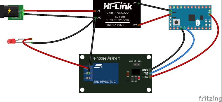
I am trying to build a relay actuator similar to this, however I have some trouble with figuring how to connect the 230 V power correctly.
My project is run on a 5 V Arduino, with a 230 V to 5 V step down regulator. Everything is soldered on a prototype board. I have also solderen on a 3.3 V step down regulator and a NRF24L01 radio. The thought behind this project is to remote control ceiling lighting.
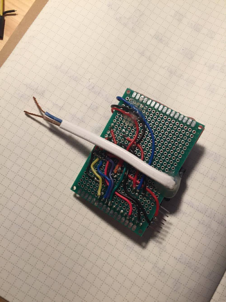
This is how it looks like now:
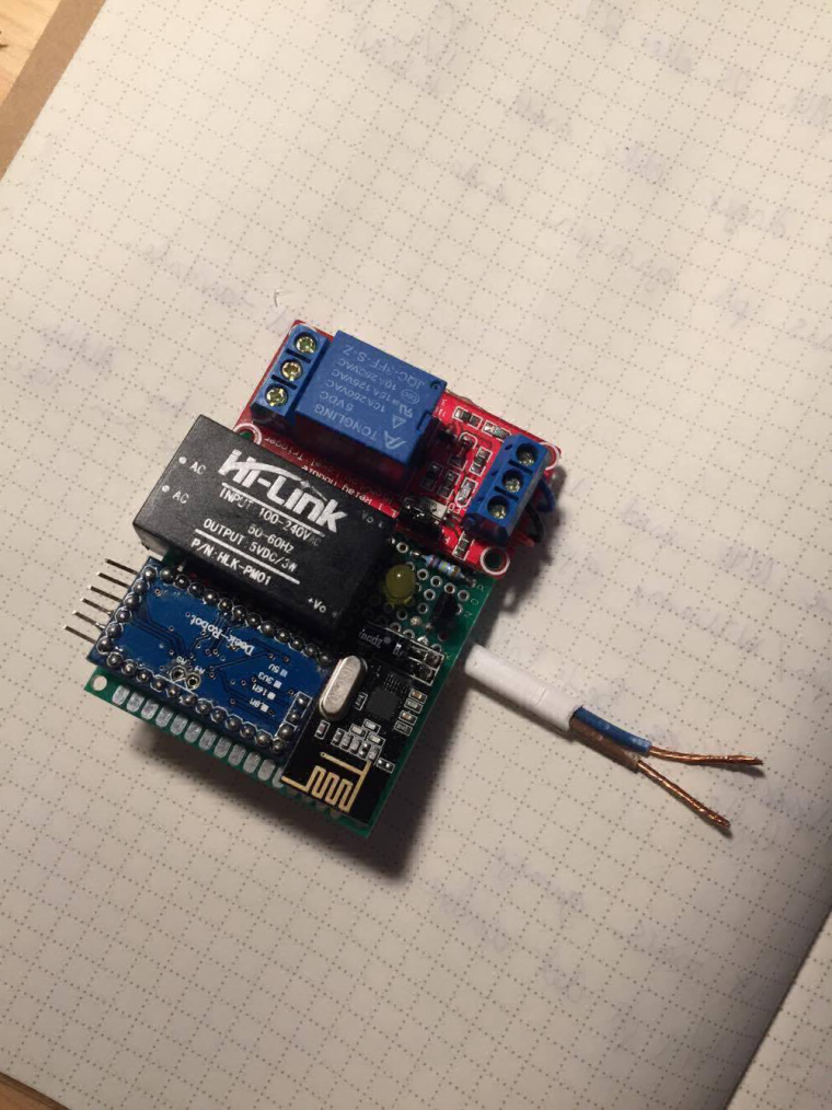
What I need help to figure out, is how to connect the 230 V to both the 5 V step down regulator AND the relay without breaking the power circuit to the Arduino when the relay turns off. I've seen projects like this before, but it seems like most of the projects only are USB powered.
All comments are welcome!
@mfalkvidd Thanks for the quick answer! I also read on the page for battery powered sensors that the step up generates alot of noise that can interfere with the radio, and that a solution might be to add capacitators (which I already tried), but also powering the radio directly from batteries. I'll try that later today. Thanks! :smiley:
And thank you for the link to the troubleshooting. It's now bookmarked! :wink: