Skip to content
  • MySensors
  • OpenHardware.io
  • Categories
  • Recent
  • Tags
  • Popular
Skins
  • Light
  • Brite
  • Cerulean
  • Cosmo
  • Flatly
  • Journal
  • Litera
  • Lumen
  • Lux
  • Materia
  • Minty
  • Morph
  • Pulse
  • Sandstone
  • Simplex
  • Sketchy
  • Spacelab
  • United
  • Yeti
  • Zephyr
  • Dark
  • Cyborg
  • Darkly
  • Quartz
  • Slate
  • Solar
  • Superhero
  • Vapor

  • Default (No Skin)
  • No Skin
Collapse
Brand Logo
SGiS

SGi

@SGi
About
Posts
20
Topics
2
Shares
0
Groups
0
Followers
0
Following
0

Posts

Recent Best Controversial

  • Heatpump Sketch Help
    SGiS SGi

    @sundberg84 Ok thanks, i thought the following part of the code in Presentation() was doing that?

    // Load our values on start
      POWER_STATE = loadState(POWER_ID);
      TEMP_STATE = loadState(TEMP_ID);
      FAN_STATE = loadState(FAN_ID);
      MODE_STATE = loadState(MODE_ID);
      
      sendHeatpumpCommand();```
    Development

  • Heatpump controller
    SGiS SGi

    @ToniA Hi, do you have a guide on how to set up Domoticz with this example? I understand enough about mysensors and domoticz to be dangerous but i dont get how Domoticz can send the right command....

    Development

  • Heatpump Sketch Help
    SGiS SGi

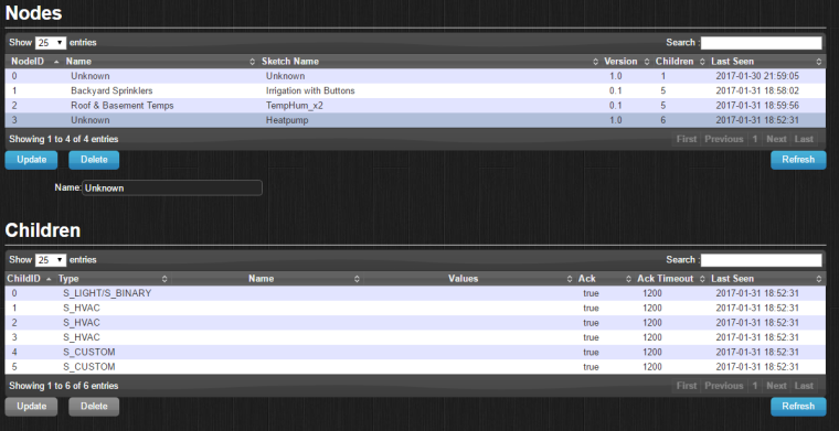
    Ok, i have managed to get a heatpump IR sketch working somewhat. I can see the node in 'hardware' and even the children but they do not appear in 'devices'... is there something fundamentally wrong in my sketch?

    I am using Domoticz and a RPI controller.

    0_1485842430447_upload-0a99d4c1-0ede-4128-a926-481cb0270315

    // Enable debug prints to serial monitor
    #define MY_DEBUG
    
    // Enable and select radio type attached
    #define MY_RADIO_NRF24
    
    #include <SPI.h>
    #include <MySensors.h>
    
    #include <MitsubishiHeatpumpIR.h>
    
    #define POWER_ID 0
    #define MODE_ID 1
    #define FAN_ID 2
    #define TEMP_ID 3
    #define VDIR_ID 4
    #define HDIR_ID 5
    
    MyMessage powerMsg(POWER_ID, V_STATUS); 
    MyMessage modeMsg(MODE_ID, V_HVAC_FLOW_STATE);
    MyMessage fanMsg(FAN_ID, V_PERCENTAGE);
    MyMessage tempMsg(TEMP_ID, V_TEMP);
    MyMessage vdirMsg(VDIR_ID, V_VAR1); 
    MyMessage hdirMsg(HDIR_ID, V_VAR2); 
    
    IRSenderPWM irSender(3);       // IR led on Arduino digital pin 3, using Arduino PWM
    
    HeatpumpIR *heatpumpIR = new MitsubishiFDHeatpumpIR();
    
    //Some global variables to hold the states
    int POWER_STATE;
    int TEMP_STATE;
    int FAN_STATE;
    int MODE_STATE;
    
    void setup()  
    {  
      // begin(incomingMessage, AUTO, false);
    }
      
    void presentation()  
    {     
      // Send the sketch version information to the gateway and Controller
      sendSketchInfo("Heatpump", "1.0");
    
      // Register all sensors to gw (they will be created as child devices)
      present(POWER_ID, S_BINARY);
      present(MODE_ID, S_HVAC);
      present(FAN_ID, S_HVAC);
      present(TEMP_ID, S_HVAC);
      present(VDIR_ID, S_CUSTOM);
      present(HDIR_ID, S_CUSTOM);
         
      // Load our values on start
      POWER_STATE = loadState(POWER_ID);
      TEMP_STATE = loadState(TEMP_ID);
      FAN_STATE = loadState(FAN_ID);
      MODE_STATE = loadState(MODE_ID);
      
      sendHeatpumpCommand();
    }
    
    void loop() {
    
    } 
    
    void handlePowerMessage(bool newState) {
      if (newState) {
        POWER_STATE = POWER_ON;
      }
      else {
        POWER_STATE = POWER_OFF;
      }
      saveState(POWER_ID, newState);
    }
    
    void handleModeMessge(int newMode) {
      switch(newMode) {    
        case 0:
          MODE_STATE = MODE_HEAT; break;
        case 1:
          MODE_STATE = MODE_COOL; break;
        case 2:
          MODE_STATE = MODE_AUTO; break;
        case 3:
          MODE_STATE = MODE_FAN; break;
         case 4:
          MODE_STATE = MODE_DRY; break;
      }
      MODE_STATE = newMode;
      saveState(MODE_ID, newMode);
    }
    
    void handleFanMessage(int newFan) {
      if (newFan > 5) newFan=5;
      switch(newFan) {
        case 0:
          FAN_STATE = FAN_AUTO; break;
        case 1:
          FAN_STATE = FAN_1; break;
        case 2:
          FAN_STATE = FAN_2; break;
        case 3:
          FAN_STATE = FAN_3; break;
        case 4:
          FAN_STATE = FAN_4; break;
        case 5:
          FAN_STATE = FAN_5; break;
        default:
          FAN_STATE = FAN_AUTO; break;
      }
      FAN_STATE = newFan;
      saveState(FAN_ID, newFan);
    }
    
    void handleTempMessage(int newTemp) {
      TEMP_STATE = newTemp;
      saveState(TEMP_ID, newTemp);
    }
    
    void sendHeatpumpCommand() {
      Serial.println("Power = " + (String)POWER_STATE);
      Serial.println("Mode = " + (String)MODE_STATE);
      Serial.println("Fan = " + (String)FAN_STATE);
      Serial.println("Temp = " + (String)TEMP_STATE);
      heatpumpIR->send(irSender, POWER_STATE, MODE_STATE, FAN_STATE, TEMP_STATE, VDIR_AUTO, HDIR_AUTO);
    }
    void incomingMessage(const MyMessage &message) {
      // We only expect one type of message from controller. But we better check anyway.
      if (message.isAck()) {
         Serial.println("This is an ack from gateway");
      }
       Serial.print("Incoming change for sensor:");
       Serial.print(message.sensor);
       Serial.print(", New status: ");
       Serial.println(message.getBool());
    
       switch(message.sensor) {
        case POWER_ID: {
          bool newState = message.getBool();
          handlePowerMessage(newState);
          break;
        }
        case MODE_ID: {
          int newMode = message.getInt();
          handleModeMessge(newMode);
          break;
        }
        case FAN_ID: {
          int newFan = message.getInt();
          handleFanMessage(newFan);
          break;
        }
        case TEMP_ID: {
          int newTemp = message.getInt();
          handleTempMessage(newTemp);
          break;
        }
       }
      sendHeatpumpCommand();
    }
    
    Development

  • Heatpump Sketch Help
    SGiS SGi

    Hi,

    I need some help converting the Heatpump sketch example to 2.0 and also isolating to just the Mitsubishi model as i have no need or memory for all the models.... i guess my biggest issue is where in the sketch is the model actually defined?

    Link to sketch that i need converting below:

    https://www.mysensors.org/build/heatpump

    Cheers
    Scott

    Development

  • Multi Button Relay Sketch
    SGiS SGi

    @Boots33 i just worked out what was wrong the code above... and now understand how the message.sensor number works... now my only issue is why the buttons on pins 2,3,4 work but not pin 1... does pin 1 on the arduino have special use?

    Development

  • Multi Button Relay Sketch
    SGiS SGi

    @Boots33 Whoa sorry, here is the code in the proper format/window...

    /**
     *******************************
     *
     * REVISION HISTORY
     * Version 0.1 - SGI
     * 
     * DESCRIPTION
     * Sketch to control 4 relays for irrigations, including 4 local push buttons.. 
     */ 
    
    // Enable debug prints to serial monitor
    #define MY_DEBUG 
    
    // Enable and select radio type attached
    #define MY_RADIO_NRF24
    //#define MY_RADIO_RFM69
    
    // Enable repeater functionality for this node
    #define MY_REPEATER_FEATURE
    
    #include <SPI.h>
    #include <MySensors.h>
    #include <Bounce2.h>
    
    // Define Relays
    #define RELAY_1  5  // Arduino Digital I/O pin number for first relay (second on pin+1 etc)
    #define NUMBER_OF_RELAYS 4 // Total number of attached relays
    #define RELAY_ON 0  // GPIO value to write to turn on attached relay
    #define RELAY_OFF 1 // GPIO value to write to turn off attached relay
    
    // Define Sensor ID's
    #define SSR_A_ID 11   // Id of the sensor child
    #define SSR_B_ID 12   // Id of the sensor child
    #define SSR_C_ID 13   // Id of the sensor child
    #define SSR_D_ID 14   // Id of the sensor child
    
    // Define Buttons
    const int buttonPinA = 1;
    const int buttonPinB = 2;
    const int buttonPinC = 3;
    const int buttonPinD = 4;
    
    // Define Variables
    int oldValueA = 0;
    int oldValueB = 0;
    int oldValueC = 0;
    int oldValueD = 0;
    bool stateA;
    bool stateB;
    bool stateC;
    bool stateD;
    
    // Define Debounce
    Bounce debouncerA = Bounce();
    Bounce debouncerB = Bounce();
    Bounce debouncerC = Bounce();
    Bounce debouncerD = Bounce();
    
    // Define messages to send back to gateway
    MyMessage msgA(SSR_A_ID, V_STATUS);
    MyMessage msgB(SSR_B_ID, V_STATUS);
    MyMessage msgC(SSR_C_ID, V_STATUS);
    MyMessage msgD(SSR_D_ID, V_STATUS);
    
    
    void setup() {
    
      // Setup relay pins and set to output then set relays to startup off
      for (int sensor=1, pin=RELAY_1; sensor<=NUMBER_OF_RELAYS;sensor++, pin++) {
        // Then set relay pins in output mode
        pinMode(pin, OUTPUT);   
        // Set relay off
        digitalWrite(pin, 1);
      }
    
      // Setup the button Activate internal pull-up
      pinMode(buttonPinA, INPUT_PULLUP); 
      pinMode(buttonPinB, INPUT_PULLUP);
      pinMode(buttonPinC, INPUT_PULLUP);
      pinMode(buttonPinD, INPUT_PULLUP);
    
      // After setting up the buttons, setup debouncer
      debouncerA.attach(buttonPinA);
      debouncerA.interval(5);
      debouncerB.attach(buttonPinB);
      debouncerB.interval(5);
      debouncerC.attach(buttonPinC);
      debouncerC.interval(5);
      debouncerD.attach(buttonPinD);
      debouncerD.interval(5);
      
    }
    
    void presentation()  
    {   
      // Send the sketch version information to the gateway and Controller
      sendSketchInfo("Irrigation with Buttons", "0.1");
      
      // Register all sensors to gw (they will be created as child devices)
      present(SSR_A_ID, S_LIGHT);
      present(SSR_B_ID, S_LIGHT);
      present(SSR_C_ID, S_LIGHT);
      present(SSR_D_ID, S_LIGHT);
    }
    
    
    void loop() 
    {
      debouncerA.update();
      // Get the update value
      int valueA = debouncerA.read();
      if (valueA != oldValueA && valueA == 0) {
        send(msgA.set(stateA?false:true), true); // Send new state and request ack back
      }
      oldValueA = valueA;
     
      debouncerB.update();
      // Get the update value
      int valueB = debouncerB.read();
      if (valueB != oldValueB && valueB == 0) {
        send(msgB.set(stateB?false:true), true); // Send new state and request ack back
      }
      oldValueB = valueB;
    
      debouncerC.update();
      // Get the update value
      int valueC = debouncerC.read();
      if (valueC != oldValueC && valueC == 0) {
        send(msgC.set(stateC ? false : true), true); // Send new state and request ack back
      }
      oldValueC = valueC;
    
      debouncerD.update();
      // Get the update value
      int valueD = debouncerD.read();
      if (valueD != oldValueD && valueD == 0) {
        send(msgD.set(stateD ? false : true), true); // Send new state and request ack back
      }
      oldValueD = valueD;  
    }
    
    void receive(const MyMessage &message) {
      // We only expect one type of message from controller. But we better check anyway.
      if (message.type==V_STATUS) {
         
        switch (message.sensor) {
          case 1:
            stateA = message.getBool();
            digitalWrite(message.sensor+4, stateA ? RELAY_ON : RELAY_OFF);
            break;
          case 2:
            stateB = message.getBool();
            digitalWrite(message.sensor+4, stateB ? RELAY_ON : RELAY_OFF);
            break;
          case 3:
            stateC = message.getBool();
            digitalWrite(message.sensor+4, stateC ? RELAY_ON : RELAY_OFF);
            break;
          case 4:
            stateD = message.getBool();
            digitalWrite(message.sensor+4, stateD ? RELAY_ON : RELAY_OFF);
            break;
            }
         // Change relay state
         // digitalWrite(message.sensor-1+RELAY_1, message.getBool()?RELAY_ON:RELAY_OFF);
         // Store state in eeprom
         //saveState(message.sensor, message.getBool());
         // Write some debug info
         Serial.print("Incoming change for sensor:");
         Serial.print(message.sensor);
         Serial.print(", New status: ");
         Serial.println(message.getBool());
       } 
    }
    
    Development

  • Multi Button Relay Sketch
    SGiS SGi

    Has anyone made a multi (at least 4) relay version of the relay with button sketch? the basic relay example sketch allows for multiple relays but the relay with button sketch only allows for 1. I am sure it would not be difficult for an experienced Arduino/MySensors programmer to modify the example sketch for me? Any takers?

    Development

  • Problems with first sensors
    SGiS SGi

    Still cant get the stutus LED's working tho... hmmmm any suggestions? i have checked the polarity and connections are good to pins 4,5,6

    Troubleshooting

  • Problems with first sensors
    SGiS SGi

    I thought my problem was dodgy Dupont cables but after more experimenting all issues have now gone by soldering a 80mm aerial to the radio :) like a magic fix....

    0_1469865212533_Capture.JPG

    Troubleshooting

  • Whare Hauora Toru
    SGiS SGi

    How can I get one of these? Do you sell them?

    OpenHardware.io

  • Problems with first sensors
    SGiS SGi

    @nielsokker Yea you are probably right, no problem now though since as soon as i hooked it up to my controller everything works fine :) dodgy wires on the gateway was the issue all along.... using the very basic node sketch i can now see it in Domoticz and watch it turn on/off every 10 secs :)

    Troubleshooting

  • Problems with first sensors
    SGiS SGi

    Ok so connections appear to be my major problem.... my dupont cables seem to be a bit dodgy... now wired with solid jumpers i can get the 'gettingstarted' sketch of the RF24 library working.

    Now i have the following log from the sensor which is encouraging but still weird:

    0_1468831166660_upload-4129d0ca-3934-4199-b4a4-5eb6553a1103

    Anything obvious now? The sketch on the sensor is the basic motionsensor one from the examples of 2.0.0 and the gateway is the serialgateway sketch... both no changes

    Troubleshooting

  • Problems with first sensors
    SGiS SGi

    Try this: https://forum.mysensors.org/topic/4316/version-2-0-isn-t-working

    Troubleshooting

  • Simple Serial Gateway and sensor does not work...
    SGiS SGi

    https://forum.mysensors.org/topic/4316/version-2-0-isn-t-working this could be the fix... Have to try tomorrow night....

    Troubleshooting

  • Simple Serial Gateway and sensor does not work...
    SGiS SGi

    @tekka thanks but that doesn't appear to change anything. Do you understand the error from the sensor debug? Is it not getting a response so it restarts or something? Basically is it more likely the sensor or gateway end with the problem?

    Troubleshooting

  • Simple Serial Gateway and sensor does not work...
    SGiS SGi

    Oh I am using a Uno for the gateway and a nano for the DHT node...

    Troubleshooting

  • Simple Serial Gateway and sensor does not work...
    SGiS SGi

    Hmmm even when I try the example battery status sketch I get the same results from the debug.... Maybe something to do with the Nano or wiring?

    Troubleshooting

  • Simple Serial Gateway and sensor does not work...
    SGiS SGi

    @tekka my node and gateway are about 1m apart

    Troubleshooting

  • Simple Serial Gateway and sensor does not work...
    SGiS SGi

    I have exactly the same problem.....

    Troubleshooting
  • Login

  • Don't have an account? Register

  • Login or register to search.
  • First post
    Last post
0
  • MySensors
  • OpenHardware.io
  • Categories
  • Recent
  • Tags
  • Popular