Skip to content
  • MySensors
  • OpenHardware.io
  • Categories
  • Recent
  • Tags
  • Popular
Skins
  • Light
  • Brite
  • Cerulean
  • Cosmo
  • Flatly
  • Journal
  • Litera
  • Lumen
  • Lux
  • Materia
  • Minty
  • Morph
  • Pulse
  • Sandstone
  • Simplex
  • Sketchy
  • Spacelab
  • United
  • Yeti
  • Zephyr
  • Dark
  • Cyborg
  • Darkly
  • Quartz
  • Slate
  • Solar
  • Superhero
  • Vapor

  • Default (No Skin)
  • No Skin
Collapse
Brand Logo
siklosiS

siklosi

@siklosi
About
Posts
31
Topics
9
Shares
0
Groups
0
Followers
0
Following
0

Posts

Recent Best Controversial

  • Node cant see gateway less than 10m Away.
    siklosiS siklosi

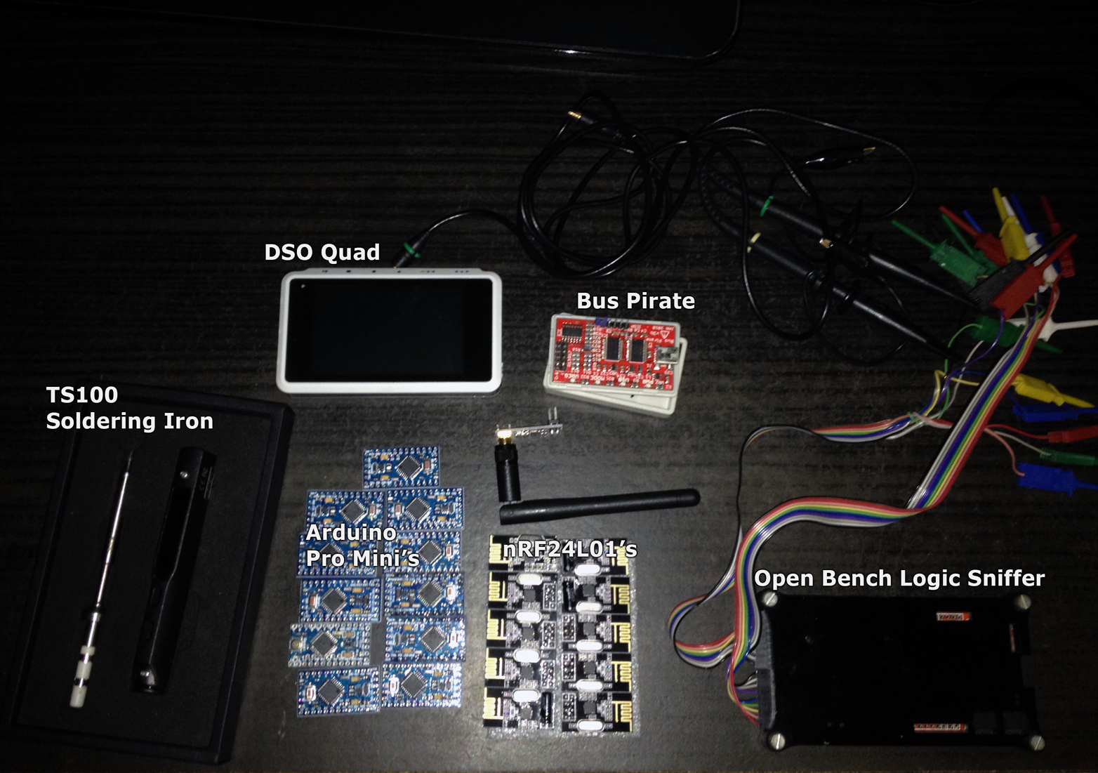
    You could scan frequencies and see what channels are free of noise and than set MySensors libraray to that channel. There is arduino code poor man's scanner that scans wifi range

    and here is my modified sketch that scans all 127 channels...

    #include <SPI.h>
    
    // Poor Man's Wireless 2.4GHz Scanner
    //
    // uses an nRF24L01p connected to an Arduino
    // 
    // Cables are:
    //     SS       -> 10
    //     MOSI     -> 11
    //     MISO     -> 12
    //     SCK      -> 13
    // 
    // and CE       ->  9
    //
    // created March 2011 by Rolf Henkel
    //
    
    #define CE  9
    
    // Array to hold Channel data
    #define CHANNELS  128
    int channel[CHANNELS];
    
    // greyscale mapping 
    int  line;
    char grey[] = " 123456789";
    
    // nRF24L01P registers we need
    #define _NRF24_CONFIG      0x00
    #define _NRF24_EN_AA       0x01
    #define _NRF24_RF_CH       0x05
    #define _NRF24_RF_SETUP    0x06
    #define _NRF24_RPD         0x09
    
    // get the value of a nRF24L01p register
    byte getRegister(byte r)
    {
      byte c;
      
      PORTB &=~_BV(2);
      c = SPI.transfer(r&0x1F);
      c = SPI.transfer(0);  
      PORTB |= _BV(2);
    
      return(c);
    }
    
    // set the value of a nRF24L01p register
    void setRegister(byte r, byte v)
    {
      PORTB &=~_BV(2);
      SPI.transfer((r&0x1F)|0x20);
      SPI.transfer(v);
      PORTB |= _BV(2);
    }
      
    // power up the nRF24L01p chip
    void powerUp(void)
    {
      setRegister(_NRF24_CONFIG,getRegister(_NRF24_CONFIG)|0x02);
      delayMicroseconds(130);
    }
    
    // switch nRF24L01p off
    void powerDown(void)
    {
      setRegister(_NRF24_CONFIG,getRegister(_NRF24_CONFIG)&~0x02);
    }
    
    // enable RX 
    void enable(void)
    {
        PORTB |= _BV(1);
    }
    
    // disable RX
    void disable(void)
    {
        PORTB &=~_BV(1);
    }
    
    // setup RX-Mode of nRF24L01p
    void setRX(void)
    {
      setRegister(_NRF24_CONFIG,getRegister(_NRF24_CONFIG)|0x01);
      enable();
      // this is slightly shorter than
      // the recommended delay of 130 usec
      // - but it works for me and speeds things up a little...
      delayMicroseconds(130);
    }
    
    // scanning all channels in the 2.4GHz band
    void scanChannels(void)
    {
      disable();
      for( int j=0 ; j<200  ; j++)
      {
        for( int i=0 ; i<CHANNELS ; i++)
        {
          // select a new channel
          setRegister(_NRF24_RF_CH,(128*i)/CHANNELS);
          
          // switch on RX
          setRX();
          
          // wait enough for RX-things to settle
          delayMicroseconds(40);
          
          // this is actually the point where the RPD-flag
          // is set, when CE goes low
          disable();
          
          // read out RPD flag; set to 1 if 
          // received power > -64dBm
          if( getRegister(_NRF24_RPD)>0 )   channel[i]++;
        }
      }
    }
    
    // outputs channel data as a simple grey map
    void outputChannels(void)
    {
      int norm = 0;
      
      // find the maximal count in channel array
      for( int i=0 ; i<CHANNELS ; i++)
        if( channel[i]>norm ) norm = channel[i];
        
      // now output the data
      //Serial.print('|');
      for( int i=0 ; i<CHANNELS ; i++)
      {
        int pos;
        
        // calculate grey value position
        if( norm!=0 ) pos = (channel[i]*10)/norm;
        else          pos = 0;
        
        // boost low values
        if( pos==0 && channel[i]>0 ) pos++;
        
        // clamp large values
        if( pos>9 ) pos = 9;
       
        // print it out
        Serial.print(grey[pos]);
        channel[i] = 0;
      }
      
      // indicate overall power
       Serial.println("");
     // Serial.println(norm);
    }
    
    // give a visual reference between WLAN-channels and displayed data
    void printChannels(void)
    {
      // output approximate positions of WLAN-channels
     Serial.println("0000000000000000000000000000000000000000000000000000000000000000000000000000000000000000000000000001111111111111111111111111111");
     Serial.println("0000000001111111111222222222233333333334444444444555555555566666666667777777777888888888899999999990000000000111111111122222222"); 
     Serial.println("1234567890123456789012345678901234567890123456789012345678901234567890123456789012345678901234567890123456789012345678901234567");
    }
    
    void setup()
    {
      Serial.begin(57600);
      
      Serial.println("Starting Poor Man's Wireless 2.4GHz Scanner ...");
      Serial.println();
    
      // Channel Layout
      // 0         1         2         3         4         5         6
      // 0123456789012345678901234567890123456789012345678901234567890123
      //       1 2  3 4  5  6 7 8  9 10 11 12 13  14                     | 
      //
     // Serial.println("Channel Layout");
      printChannels();
      
      // Setup SPI
      SPI.begin();
      SPI.setDataMode(SPI_MODE0);
      SPI.setClockDivider(SPI_CLOCK_DIV2);
      SPI.setBitOrder(MSBFIRST);
      
      // Activate Chip Enable
      pinMode(CE,OUTPUT);
      disable();
      
      // now start receiver
      powerUp();
      
      // switch off Shockburst
      setRegister(_NRF24_EN_AA,0x0);
      
      // make sure RF-section is set properly 
      // - just write default value... 
      setRegister(_NRF24_RF_SETUP,0x0F); 
      
      // reset line counter
      line = 0;
    }
    
    void loop() 
    { 
      // do the scan
      scanChannels();
      
      // output the result
      outputChannels();
      
      // output WLAN-channel reference every 12th line
      if( line++>12 )
      {
        printChannels();
        line = 0;
      }
    }
    
    Troubleshooting

  • RGB Servo spot
    siklosiS siklosi

    This is little project I made while ago but just now converted it to mysensors (used to be controlled via bluetooth)
    2_1454273523371_image1 (4).JPG 1_1454273523371_image2.PNG 0_1454273523370_image3 (1).JPG

    
    #include <MySensor.h>
    #include <SPI.h>
    #include <Servo.h>
    
    #define RED_PIN 3
    #define GREEN_PIN 5
    #define BLUE_PIN 6
    #define SERVO_H 7
    #define SERVO_V 8
    
    #define NODE_ID 5
    #define SERVO_RGB 0
    #define SKETCH_NAME "SERVO RGB"
    #define SKETCH_VERSION "1.0.0"
    #define NODE_REPEAT false
    #define FIRE_EFFECT 22
    
    Servo myservo_h;
    Servo myservo_v;
    MySensor gw;
    
    long RGB_values[3] = {0, 0, 0};
    float dimmer;
    //int r = 255;
    //int g = r - 80;
    //int b = 25;
    //int servh = 0;
    //int servv = 0;
    
    //MyMessage fireMsg(FIRE_EFFECT, V_LIGHT);
    
    void setup() {
    
      pinMode(RED_PIN, OUTPUT);
      pinMode(GREEN_PIN, OUTPUT);
      pinMode(BLUE_PIN, OUTPUT);
      pinMode(SERVO_H, OUTPUT);
      pinMode(SERVO_V, OUTPUT);
      gw.begin(incomingMessage, NODE_ID, NODE_REPEAT);
      gw.sendSketchInfo(SKETCH_NAME, SKETCH_VERSION);
      
      gw.present(SERVO_RGB, S_RGB_LIGHT, "Servo RGB", false);
      gw.present(SERVO_V, S_LIGHT, "Servo V", false);
      gw.present(SERVO_H, S_LIGHT, "Servo H", false);
      gw.request(SERVO_V, V_LIGHT);
      gw.request(SERVO_V, V_LIGHT);
      gw.request(SERVO_RGB, V_RGB);
    }
    
    void loop() {
      gw.process();
    
    }
    
    
    void incomingMessage(const MyMessage &message) {
    
      if (message.type == V_RGB) {
    
        String hexstring = message.getString();
        long number = (long) strtol( &hexstring[0], NULL, 16);
        RGB_values[0] = number >> 16;
        RGB_values[1] = number >> 8 & 0xFF;
        RGB_values[2] = number & 0xFF;
      }
      if (message.type == V_DIMMER) {
    
        if (message.sensor == SERVO_V) {
          myservo_v.attach(SERVO_V);
          myservo_v.write(map(message.getInt(), 0, 100, 72, 180));
          gw.wait(1000);
          myservo_v.detach();
        }
        if (message.sensor == SERVO_H) {
          myservo_h.attach(SERVO_H);
          myservo_h.write(map(message.getInt(), 0, 100, 0, 180));
          gw.wait(1000);
          myservo_h.detach();
        }
        if (message.sensor == SERVO_RGB) {
          dimmer = message.getInt();
          analogWrite(RED_PIN, int(RGB_values[0] * (dimmer / 100)));
          analogWrite(GREEN_PIN, int(RGB_values[1] * (dimmer / 100)));
          analogWrite(BLUE_PIN, int(RGB_values[2] * (dimmer / 100)));
        }
      }
    
      if (message.type == V_LIGHT) {
        if (message.sensor == SERVO_RGB) {
          if (message.getInt() == 0) {
            digitalWrite(RED_PIN, 0);
            digitalWrite(GREEN_PIN, 0);
            digitalWrite(BLUE_PIN, 0);
          }
          if (message.getInt() == 1) {
            analogWrite(RED_PIN, int(RGB_values[0] * (dimmer / 100)));
            analogWrite(GREEN_PIN, int(RGB_values[1] * (dimmer / 100)));
            analogWrite(BLUE_PIN, int(RGB_values[2] * (dimmer / 100)));
          }
        }
        if (message.sensor == SERVO_H) {
          if (message.getInt() == 0) {
            myservo_h.attach(SERVO_H);
            myservo_h.write(0);
            gw.wait(1000);
            myservo_h.detach();
          }
          if (message.getInt() == 1) {
            myservo_v.attach(SERVO_V);
            myservo_v.write(180);
            gw.wait(1000);
            myservo_v.detach();
          }
        }
      }
    }
    
    
    My Project

  • Your tools :)
    siklosiS siklosi

    OK Ill start :)
    0_1459966034594_toys.png

    DSO Quad - Digital Osciloscope
    TS100 - Soldering Iron
    Bus Pirate - open source "hacker" multi-tool
    Open Bench Logic Sniffer - open source logic analyzer

    General Discussion

  • Send color data to sensors
    siklosiS siklosi

    @davy39
    I just made RGB controller for domoticz. So if it's not to late...

    
    #include <MySensor.h>
    #include <SPI.h>
    
    #define RED_PIN 3
    #define GREEN_PIN 5
    #define BLUE_PIN 6
    
    #define NODE_ID 2
    #define CHILD_ID 0
    #define SKETCH_NAME "RGB_STRIP"
    #define SKETCH_VERSION "1.0.0"
    #define NODE_REPEAT false
    
    MySensor gw;
    
    long RGB_values[3] = {0, 0, 0};
    float dimmer;
    
    void setup() {
    
    
      pinMode(RED_PIN, OUTPUT);
      pinMode(GREEN_PIN, OUTPUT);
      pinMode(BLUE_PIN, OUTPUT);
    
      gw.begin(incomingMessage, NODE_ID, NODE_REPEAT);
      gw.sendSketchInfo(SKETCH_NAME, SKETCH_VERSION);
      gw.present(CHILD_ID, S_RGB_LIGHT, "RGB Strip", false);
      gw.request(CHILD_ID, V_RGB);
    }
    
    void loop() {
      gw.process();
    }
    
    void incomingMessage(const MyMessage &message) {
    
      if (message.type == V_RGB) {
    
        String hexstring = message.getString();
        long number = (long) strtol( &hexstring[0], NULL, 16);
        RGB_values[0] = number >> 16;
        RGB_values[1] = number >> 8 & 0xFF;
        RGB_values[2] = number & 0xFF;
      }
      if (message.type == V_DIMMER) {
        dimmer = message.getInt();
        analogWrite(RED_PIN, int(RGB_values[0] * (dimmer / 100)));
        analogWrite(GREEN_PIN, int(RGB_values[1] * (dimmer / 100)));
        analogWrite(BLUE_PIN, int(RGB_values[2] * (dimmer / 100)));
      }
    
      if (message.type == V_LIGHT) {
        if (message.getInt() == 0) {
          digitalWrite(RED_PIN, 0);
          digitalWrite(GREEN_PIN, 0);
          digitalWrite(BLUE_PIN, 0);
    
        }
        if (message.getInt() == 1) {
          analogWrite(RED_PIN, int(RGB_values[0] * (dimmer / 100)));
          analogWrite(GREEN_PIN, int(RGB_values[1] * (dimmer / 100)));
          analogWrite(BLUE_PIN, int(RGB_values[2] * (dimmer / 100)));
        }
      }
    }
    
    
    PiDome controller color

  • Power meter
    siklosiS siklosi

    Hi,
    I just saw article on HackaDay about guy reverse engineering cheap power meter.

    http://hackaday.com/2016/07/11/put-a-reverse-engineered-power-meter-in-your-toolkit/

    http://webx.dk/oz2cpu/energy-meter/energy-meter.htm

    Here is the power meter on aliexpress

    http://www.aliexpress.com/item/LCD-4IN1-display-Voltage-current-active-power-energy-meter-blue-backlight-panel-voltmeter-ammeter-kwh-0/32611189341.html

    It looks interesting and adding MySensors to it would be great.

    Hardware

  • Raspberry Pi Zero $5
    siklosiS siklosi

    https://www.raspberrypi.org/blog/raspberry-pi-zero

    For this price Pi can now bi used as node :smiley:

    General Discussion

  • one question ! about interference wave !
    siklosiS siklosi

    I modified poor man's scanner script so that you can see all 127 channels..

    http://forum.mysensors.org/topic/2454/node-cant-see-gateway-less-than-10m-away/11

    Vera

  • Suggestion for project conversio
    siklosiS siklosi

    Hi,
    I built while ago this little thingie
    rgb servo spot
    I used arduino with bluetooth. Now my nrf240l rf's came along with arduino mini's. And i built gw with one test borad to verify that everything is working with domoticz (and it is :) ). Now I would like to convert this servo rgb spot. It has rgb leds (actualy 3 separate led's but effect is same) and two servos for for two axes. What would be best way to controll it (mysensots and domoticz solution) also im thinking about buying some eeproms and i installing some ota bootloader. AT25640 are ok?

    Development

  • CH340G okay for sensors?
    siklosiS siklosi

    Mac OS X Sierra driver
    Working also with Mac OS, but Sierra crashes and here is link for working driver

    Hardware

  • Atypical use of MySensors library some questions...
    siklosiS siklosi

    It's just an idea in developement/testing that will be presented if it work's as intended and reliable... Sensor for parking spot in parking garage with red/green led that shows if parking spot is free and also sends how many parking spots are free... Maybe some lcd tv that will show you when you are entering garage where are free spots...

    Development

  • MYSBootloader 1.3 pre-release & MYSController 1.0.0beta
    siklosiS siklosi

    Is there a way to send ota firmware to node using some cli (python or...) script? I'm using MySensors with domoticz on RPi and when flashing new firmware I usually disconnect gw from rpi plug it into notebook and send fw using MYSController. If I could just disable gw in domoticz and send fw using some script it would be great until (if) domoticz gets support for ota fw.

    Development ota myscontroller mysbootloader

  • AC IR code decrypting
    siklosiS siklosi

    Maybe this will work
    0_1469012872255_upload-7ea967fd-ad75-4816-b5fa-90a88126d92f

    Development
  • Login

  • Don't have an account? Register

  • Login or register to search.
  • First post
    Last post
0
  • MySensors
  • OpenHardware.io
  • Categories
  • Recent
  • Tags
  • Popular