Air particulate sensor.
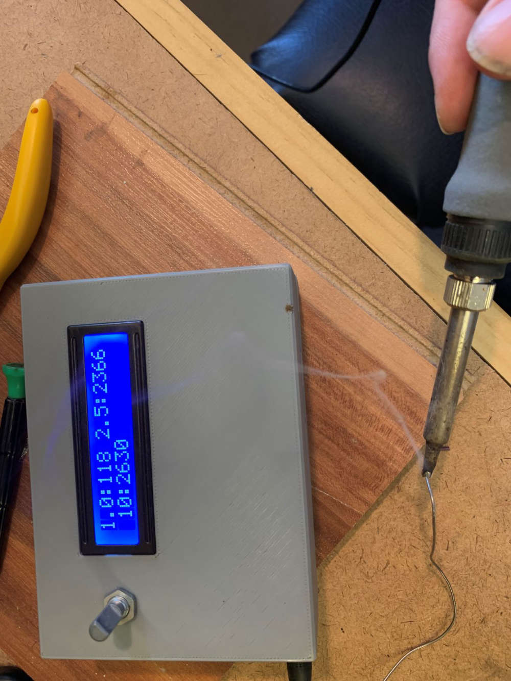
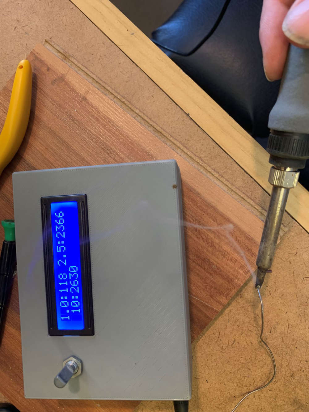
BTW, solder fumes seem to be bad for you........
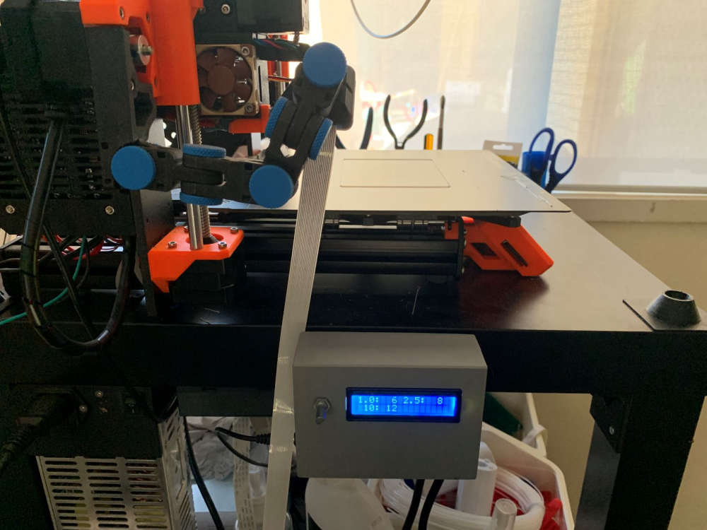
Air particulate sensor.
BTW, solder fumes seem to be bad for you........


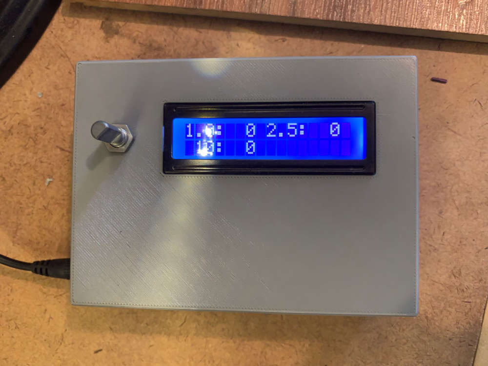
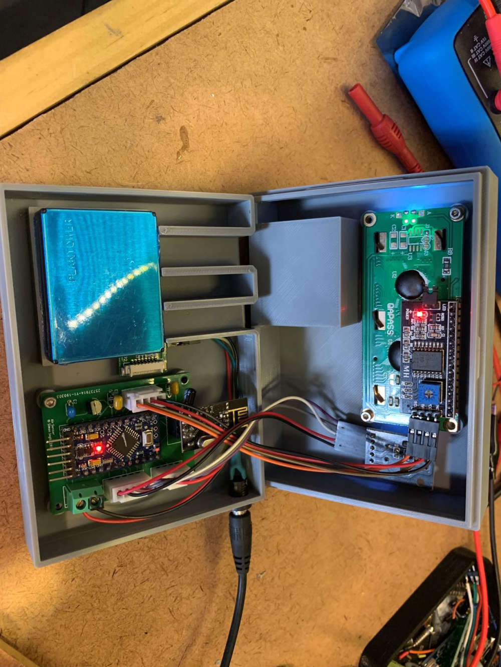
I'm sharing my latest project which is a air particulate sensor based on the PMS7003 module.
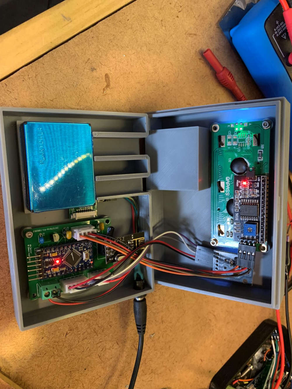
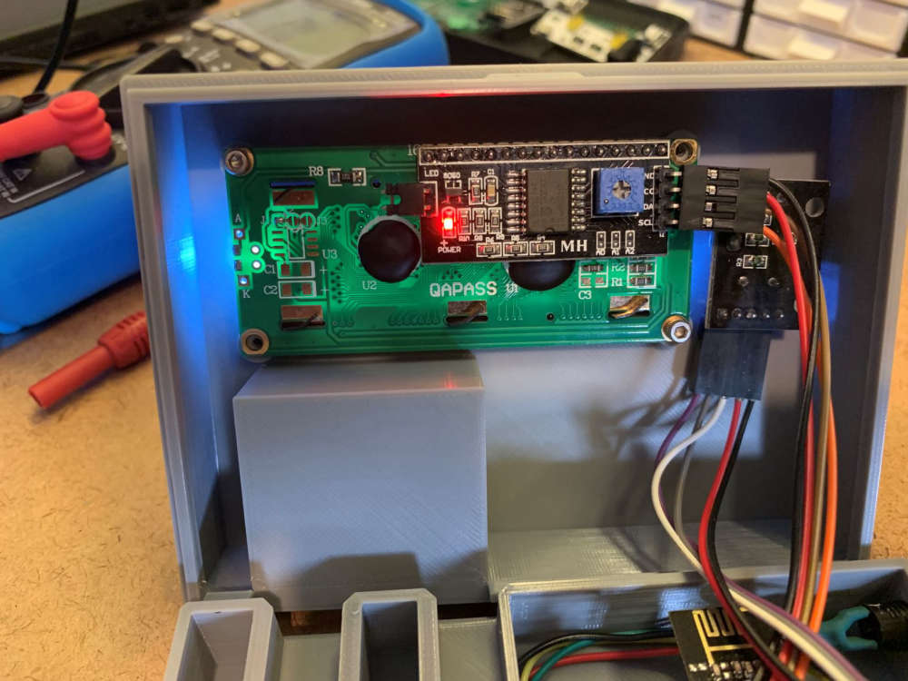
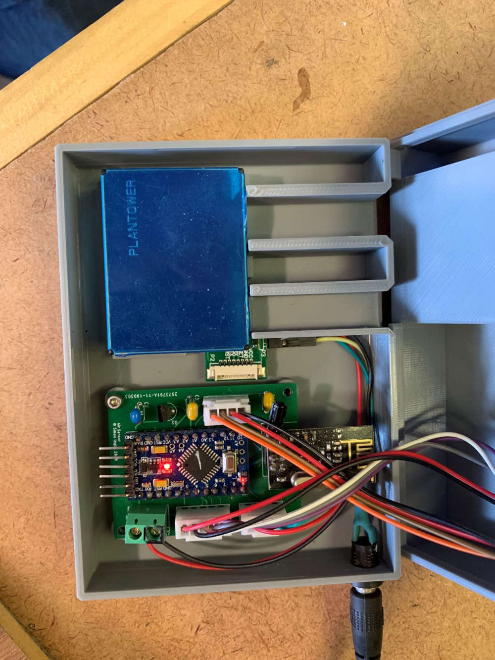
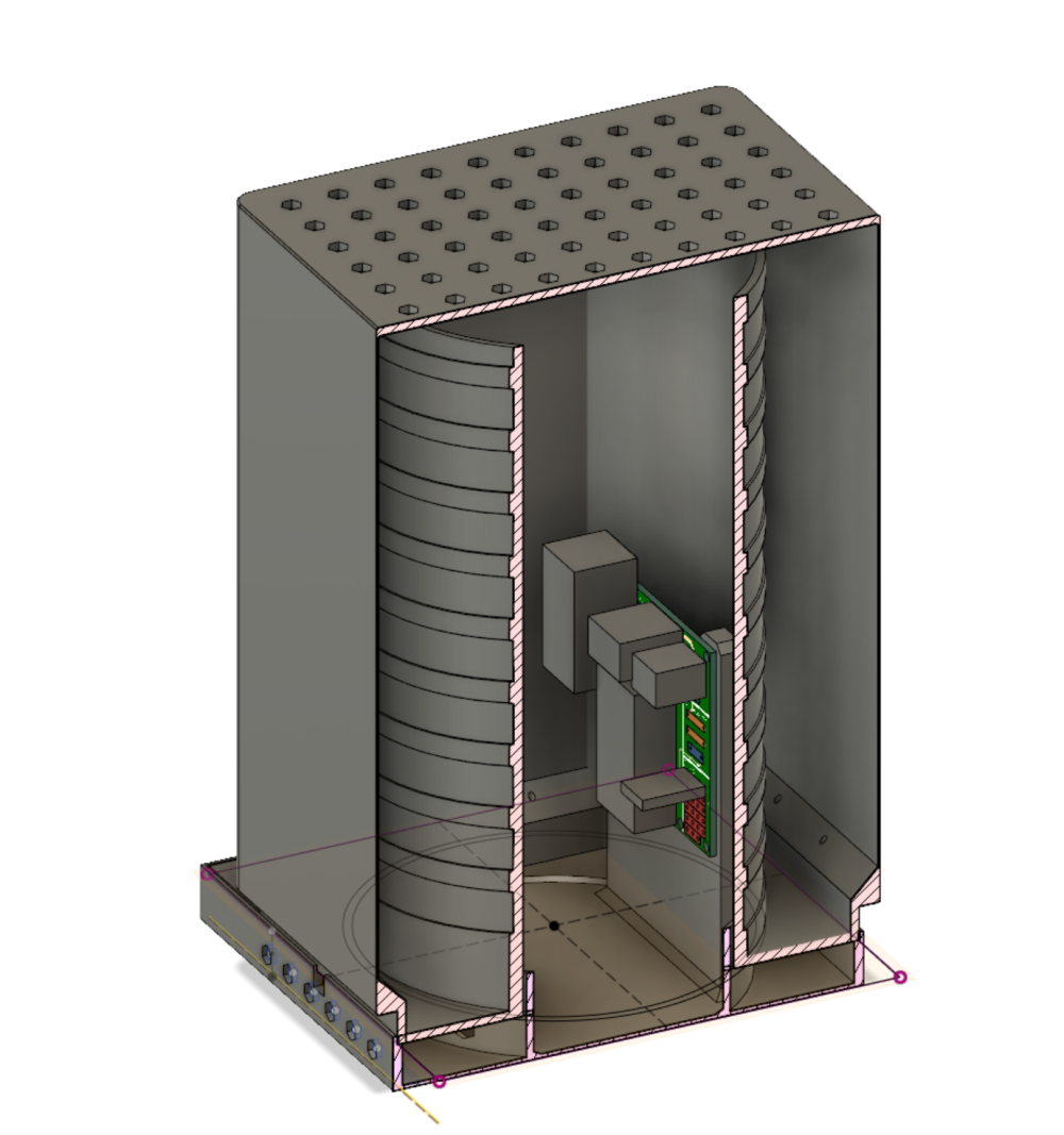
I designed a custom PCB to break out all the connectors as well as a 3D printed enclosure.
The node uses a 5v pro mini as well as the common 1602 LCD. A LE33 is used to regulate down to 3v3 for the NRF24.
My latest board that hasn't been built up yet also includes an I2C breakout for temp / humidity / barometric pressure.
The PMS7003 module is physically a bit of a pain as the intake / exhaust ports are on the same side as the connector. The case had to be designed with channels to manage the air and out whilst keeping clearances for the wire connectors.
I've mounted mine next to my 3D printer to see what the 3D printed does to the air quality inside the house.
Happy to share the PCB, code and the 3D model if there's any interest.
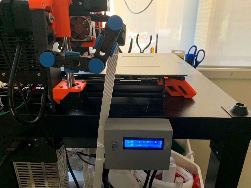
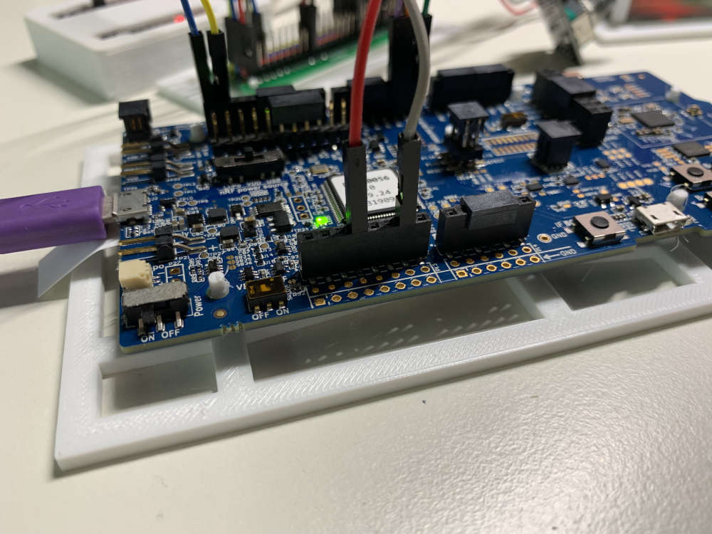
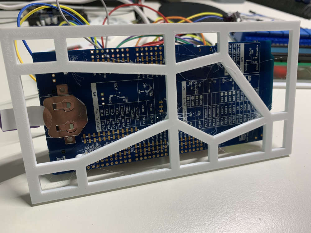
Someone may get some reuse out of this. I've made a 3d printed prototyping rig for the NRF52840 DK board as part of my MySensors adventures....
https://www.thingiverse.com/thing:3836487
I made a thing :)
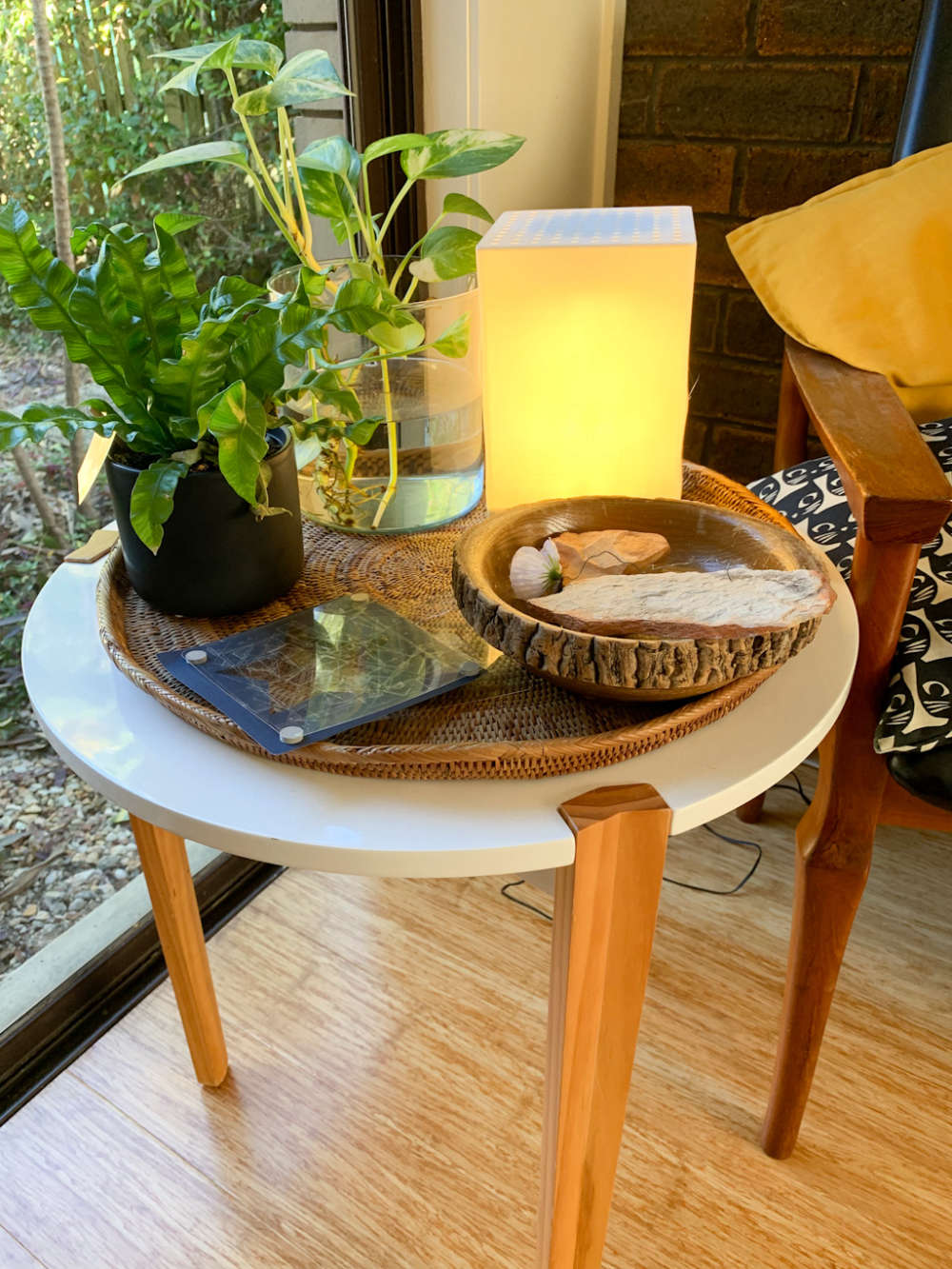
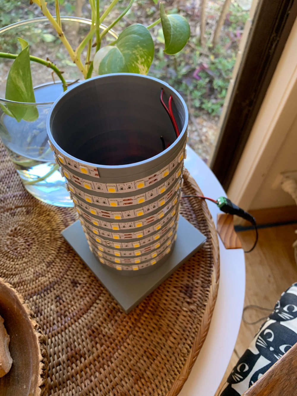
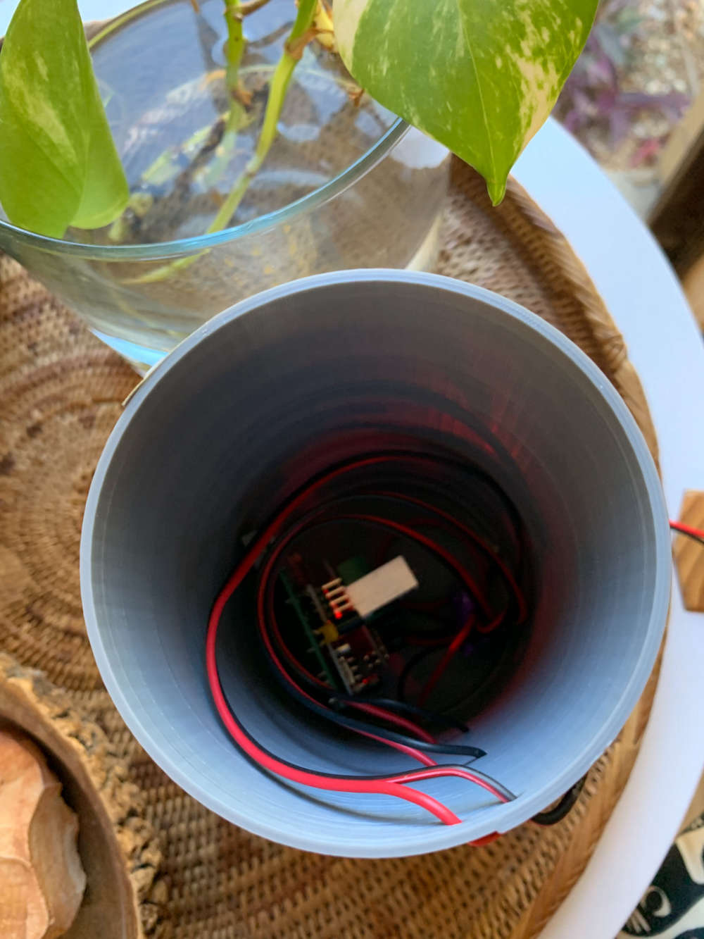
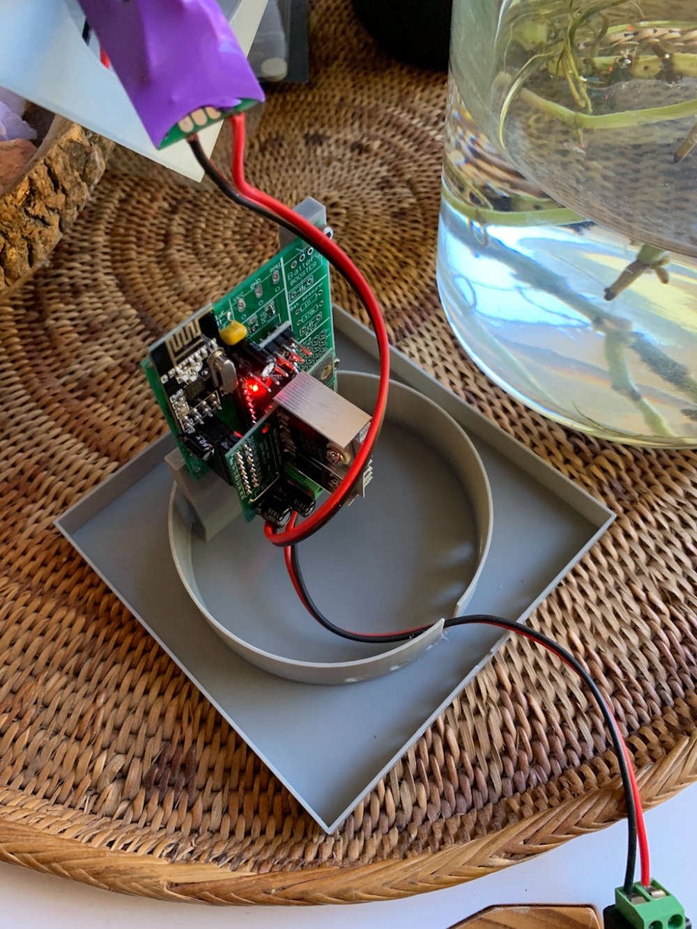
I used @sunberg84 's LED dimmer and Newbie boards (https://www.openhardware.io/view/552/Dimmable-Led-Strip-board-MysX) (https://www.openhardware.io/view/389/EasyNewbie-PCB-RFM69-HWW-edition-for-MySensors) to make some desk lamps using warm white 5050 LED strips from the ebays.
All up, it probably cost about $12 AUD to make excluding the 12v power adapter. Luckly I had some old ones laying around. Otherwise the power adapter alone would be more expensive than the lamp!
I 3D printed the parts to make the lamp in PLA plastic.
I've been monitoring the temps and the MOFSET seems to make the most heat. If you don't use a heat-sink, it gets to approx 45 deg C with the ambient of approx 20 deg C. With a heat-sink, it's about 30 deg C! I strongly recommend using heat-sinks. Note that the white lamp shade warped during printing, not from use of the lamp!
It's designed to be a convection pipe which does seem to keep the air moving well. I'm happy with the temps and the PLA plastic especially with the heat sinks on the MOFSET and voltage regulator.
The lamp draws about 12W when it's 100% on @ approx 1.1A. I'm using a 2A power supplies to be on the safe side.
If there is any interest, I'll post the designs and BOM on Thingiverse.
BTW, I've found MySensors to be much more reliable and responsive than the Ikea Tradfri lights I have in my house :)
A related thread: https://forum.mysensors.org/topic/6843/re-request-presentation
How can we send a I_PRESENT or I_REBOOT command using the HA / MySensors API? If there's a way, then an automation be be hard-coded to request each node to reboot.
Howdy,
Is it possible to rename MySensor nodes in Home Assistant? I've noticed that I can't use the normal method to rename by clicking on the cog in the Developer States window.
Cheers,
Simon.
Hi All,
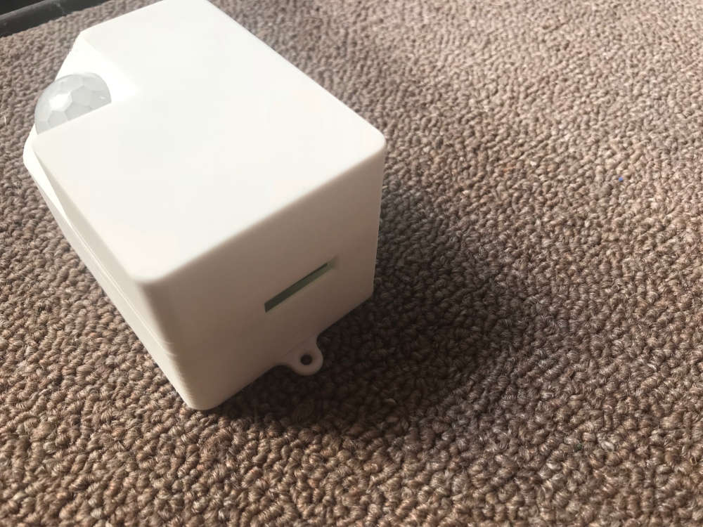
Just knocked up a case for @sundberg84 's Newbie PCB with Dimmer module. Thanks to @sundberg84 for the great PCB's.
This is the first version, and the clearances are rather generous which makes the case bigger than it needs to be. Further revisions will try and get this down to make the overall size smaller.
As you can see in the photos, the print around the aperture is a little scabby, but I think that has more to do with my poor placement of supports rather than the model itself.
The case is a press fit with snap clasps.
Files over on thingiverse here: https://www.thingiverse.com/thing:3135667
Enjoy!
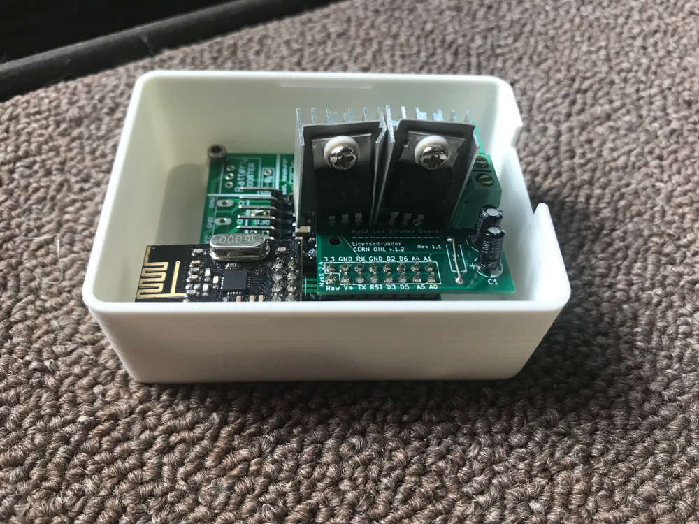
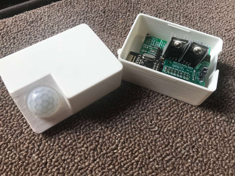
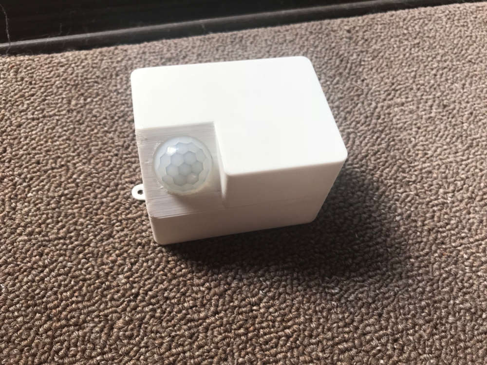
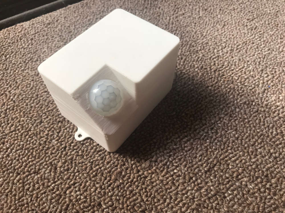
 !
!
In your next rev, perhaps you increase the spacing between the voltage regulator and the MOFSET to accommodate heat sinks? The minimum would be 2.54mm.
Howdy,
I'm loving the NodeManager for my temperature, humidity and repeater nodes. I've just built a battery power meter node and noticed some weird behavior. I'm using the latest version 1.7.
The pulse sensor can interrupt < 1 second. That is to say, the pulse frequency can be less than 1 second at certain periods of the day. I find that I can't get the sensor to report because the node interrupts and then sleeps and then interrupts again before the sleep expires and wakes to send the report. So in the debug, all you see is the interrupt processing and never a send.
Just for debug, I've set both the sleep and report interval to 1 second and I've seen this behavior. What I would like to do is to set the sleep and report interval to 5 minutes, but I don't think that it would ever report.
Any thoughts?
Hi All,
Thanks Sundberg84 for creating a board where I can knock out sensors in the matter of minutes instead of hours. :)
That being said, I actually spent many hours on the weekend trying to get my first board to work so I thought that I'd share so it could benefit others.
I was setting up a 3v3 board with 2 x AA batteries with the battery pad jumpered and using the 3v3 booster. I triple checked the board for continuity.
I was suffering from !TSM:FPAR:FAIL messages when firing up the node using the FTDI adaptor. I found that the board didn't work when both the battery and FTDI were supplying power.
Here are my lessons:
Thanks again, and I look forward to knocking out some nodes super quick.
Cheers,
Simon.
Awesome...thanks.
Ok....That sounds reasonable. I am assuming that is set with the #define MY_RF24_CHANNEL?
Howdy,
Title says it all. I'd like to have the ability to build and debug sensors with a test gateway and have a way to present to the production gateway when they've been tested.
I am mostly using SenseBenders in my production setup, with a few Nano's as repeaters.
Any ideas on how to be able to run up a sensor without it presenting to the production gateway?
Why do I want to do this? I've had issues when using HomeAssistant keeping the state of test child sensors that change while I'm still working and debugging the sketch. I'd like to run a test HomeAssistant with the test gateway.
Thanks,
Simon.
I'm an idiot.......
I just noticed a binary_sensor.nodemanager_113_3 was created in the dev-state page.
Howdy,
I have added a new SenseBender NodeManger which is visible in the dev-states screen. However one of the children sensors is not showing in the dev-states screen in HA . Specifically the door sensor which is child sensor #3. Below is a copy and paste from the dev-states screen.
sensor.nodemanager_113_1	24.99	battery_level: 100
child_id: 1
description:
device: /dev/ttyACM1
node_id: 113
V_TEMP: 24.99
unit_of_measurement: °C
friendly_name: NodeManager 113 1
sensor.nodemanager_113_2	69.01	battery_level: 100
child_id: 2
description:
device: /dev/ttyACM1
node_id: 113
V_HUM: 69.01
unit_of_measurement: %
friendly_name: NodeManager 113 2
sensor.nodemanager_113_200	SLEEPING	battery_level: 100
child_id: 200
description:
device: /dev/ttyACM1
node_id: 113
V_CUSTOM: SLEEPING
friendly_name: NodeManager 113 200
sensor.nodemanager_113_201	3.34	battery_level: 100
child_id: 201
description:
device: /dev/ttyACM1
node_id: 113
V_VOLTAGE: 3.34
unit_of_measurement: V
friendly_name: NodeManager 113 201
I'm successfully running a number of other NodeManager SenseBender nodes on HA with just temp and humidity.
The mysensors.json file appears to be showing the correct number of children sensors, including sensor #3 which is the door sensor:
"113": {
    "sensor_id": 113,
    "children": {
      "1": {
        "id": 1,
        "type": 6,
        "description": "",
        "values": {
          "0": "24.99"
        }
      },
      "2": {
        "id": 2,
        "type": 7,
        "description": "",
        "values": {
          "1": "69.01"
        }
      },
      "3": {
        "id": 3,
        "type": 23,
        "description": "",
        "values": {
          "16": "1"
        }
      },
      "200": {
        "id": 200,
        "type": 23,
        "description": "",
        "values": {
          "48": "SLEEPING"
        }
      },
      "201": {
        "id": 201,
        "type": 30,
        "description": "",
        "values": {
          "38": "3.34"
        }
      }
    },
I know that the door sensor is working as child sensor #200 shows the change to the wake / sleeping state when the NodeManager wakes up from the door sensor interrupt. Also, I can see that the NodeManager is sending the message in the serial console on change to the door sensor,
Any thoughts as to why child sensor #3 is not showing in HA?
Thanks,
Simon
@simbo said:
I was never able to sort out the programming issue using the stock Linux Arduino IDE package.
I spent some time installing the PlatformIO package on Arch Linux which allowed me to reliably upload to the sense bender. It was a bit of mucking about to get it installed, but it seems to work for me. Plus give me the command line any day over an IDE! :)
Hi,
I have an intermittent problem where I can not always upload my sketch to my Sensebender.
The Sensebender is running a modified version of the Sensebender sketch and shows the expected debug on the serial monitor, indicating that it has completed the setup, and then moved into the main loop and reading the sensors with reasonable values. I just don't seem to be able to upload a new version of the sketch reliably.
What has worked previously has been to upload the ClearEPROM sketch, and when that is sucessful, upload my modified Sensebender sketch. This is not working now.
In my ignorance, it feels like there is some timing factor going that would allow me to upload the ClearEPROM sketch.
Since I can see the serial debug, I assume the problem isn't with my FTDI USB adaptor.
I've checked the soldering on the header for the FTDI and that seems good, and I assume it must be because I can see the the sketch debug in the serial monitor?
I am using the Arduino 1.6.9 IDE on Arch Linux with the Mysensors 2.0.0 library. I've not modified the bootloader.
I'm using the FTDI adaptor linked from the MySensors store.
What follows is the the verbose messages from the IDE when uploading failed:
Sketch uses 21,244 bytes (69%) of program storage space. Maximum is 30,720 bytes.
Global variables use 861 bytes (42%) of dynamic memory, leaving 1,187 bytes for local variables. Maximum is 2,048 bytes.
/home/singlis/.arduino15/packages/arduino/tools/avrdude/6.3.0-arduino2/bin/avrdude -C/home/singlis/.arduino15/packages/arduino/tools/avrdude/6.3.0-arduino2/etc/avrdude.conf -v -patmega328p -cstk500v1 -P/dev/ttyUSB0 -b19200 -Uflash:w:/tmp/build16801fad7f0386b38002733e635aa592.tmp/SenseBender.ino.hex:i

avrdude: Version 6.3, compiled on Jun 14 2016 at 17:17:01
         Copyright (c) 2000-2005 Brian Dean, http://www.bdmicro.com/
         Copyright (c) 2007-2014 Joerg Wunsch

         System wide configuration file is "/home/singlis/.arduino15/packages/arduino/tools/avrdude/6.3.0-arduino2/etc/avrdude.conf"
         User configuration file is "/home/singlis/.avrduderc"
         User configuration file does not exist or is not a regular file, skipping

         Using Port                    : /dev/ttyUSB0
         Using Programmer              : stk500v1
         Overriding Baud Rate          : 19200
avrdude: stk500_recv(): programmer is not responding
avrdude: stk500_getsync() attempt 1 of 10: not in sync: resp=0x00
avrdude: stk500_recv(): programmer is not responding
avrdude: stk500_getsync() attempt 2 of 10: not in sync: resp=0x00
avrdude: stk500_recv(): programmer is not responding
avrdude: stk500_getsync() attempt 3 of 10: not in sync: resp=0x00
avrdude: stk500_recv(): programmer is not responding
avrdude: stk500_getsync() attempt 4 of 10: not in sync: resp=0x00
avrdude: stk500_recv(): programmer is not responding
avrdude: stk500_getsync() attempt 5 of 10: not in sync: resp=0x00
avrdude: stk500_recv(): programmer is not responding
avrdude: stk500_getsync() attempt 6 of 10: not in sync: resp=0x00
avrdude: stk500_getsync() attempt 7 of 10: not in sync: resp=0xe8
avrdude: stk500_getsync() attempt 8 of 10: not in sync: resp=0xda
avrdude: stk500_getsync() attempt 9 of 10: not in sync: resp=0x1a
avrdude: stk500_getsync() attempt 10 of 10: not in sync: resp=0xc8

avrdude done.  Thank you.

Problem uploading to board.  See http://www.arduino.cc/en/Guide/Troubleshooting#upload for suggestions.
I've also run the programmer from the command line with increased debug verbosity:
[singlis@localhost SenseBender]$ /home/singlis/.arduino15/packages/arduino/tools/avrdude/6.3.0-arduino2/bin/avrdude -v -v -v -v -C/home/singlis/.ardu
ino15/packages/arduino/tools/avrdude/6.3.0-arduino2/etc/avrdude.conf -v -patmega328p -cstk500v1 -P/dev/ttyUSB0 -b19200 -Uflash:w:/tmp/buildd81c5a6658
2a8d9d1e847e29ff4d6e6b.tmp/ClearEepromConfig.ino.hex:i

avrdude: Version 6.3, compiled on Jun 14 2016 at 17:17:01
         Copyright (c) 2000-2005 Brian Dean, http://www.bdmicro.com/
         Copyright (c) 2007-2014 Joerg Wunsch

         System wide configuration file is "/home/singlis/.arduino15/packages/arduino/tools/avrdude/6.3.0-arduino2/etc/avrdude.conf"
         User configuration file is "/home/singlis/.avrduderc"
         User configuration file does not exist or is not a regular file, skipping

         Using Port                    : /dev/ttyUSB0
         Using Programmer              : stk500v1
         Overriding Baud Rate          : 19200
avrdude: Send: 0 [30]   [20]
avrdude: Send: 0 [30]   [20]
avrdude: Send: 0 [30]   [20]
avrdude: ser_recv(): programmer is not responding
avrdude: stk500_recv(): programmer is not responding
avrdude: stk500_getsync() attempt 1 of 10: not in sync: resp=0x00
avrdude: Send: 0 [30]   [20]
avrdude: ser_recv(): programmer is not responding
avrdude: stk500_recv(): programmer is not responding
avrdude: Send: 0 [30]   [20]
avrdude: Recv: . [e8]
avrdude: stk500_getsync() attempt 3 of 10: not in sync: resp=0xe8
avrdude: Send: 0 [30]   [20]
avrdude: Recv: . [9a]
avrdude: stk500_getsync() attempt 4 of 10: not in sync: resp=0x9a
avrdude: Send: 0 [30]   [20]
avrdude: Recv: . [1a]
avrdude: stk500_getsync() attempt 5 of 10: not in sync: resp=0x1a
avrdude: Send: 0 [30]   [20]
avrdude: Recv: . [c8]
avrdude: stk500_getsync() attempt 6 of 10: not in sync: resp=0xc8
avrdude: Send: 0 [30]   [20]
avrdude: Recv: . [f2]
avrdude: stk500_getsync() attempt 7 of 10: not in sync: resp=0xf2
avrdude: Send: 0 [30]   [20]
avrdude: Recv: . [c0]
avrdude: stk500_getsync() attempt 8 of 10: not in sync: resp=0xc0
avrdude: Send: 0 [30]   [20]
avrdude: Recv: . [aa]
avrdude: stk500_getsync() attempt 9 of 10: not in sync: resp=0xaa
avrdude: Send: 0 [30]   [20]
avrdude: Recv: . [f2]
avrdude: stk500_getsync() attempt 10 of 10: not in sync: resp=0xf2

avrdude done.  Thank you.
Here's the log from the IDE when an upload succeeeds:
Sketch uses 21,244 bytes (69%) of program storage space. Maximum is 30,720 bytes.
Global variables use 861 bytes (42%) of dynamic memory, leaving 1,187 bytes for local variables. Maximum is 2,048 bytes.
/home/singlis/.arduino15/packages/arduino/tools/avrdude/6.3.0-arduino2/bin/avrdude -C/home/singlis/.arduino15/packages/arduino/tools/avrdude/6.3.0-arduino2/etc/avrdude.conf -v -patmega328p -carduino -P/dev/ttyUSB0 -b57600 -D -Uflash:w:/tmp/build16801fad7f0386b38002733e635aa592.tmp/SenseBender.ino.hex:i

avrdude: Version 6.3, compiled on Jun 14 2016 at 17:17:01
         Copyright (c) 2000-2005 Brian Dean, http://www.bdmicro.com/
         Copyright (c) 2007-2014 Joerg Wunsch

         System wide configuration file is "/home/singlis/.arduino15/packages/arduino/tools/avrdude/6.3.0-arduino2/etc/avrdude.conf"
         User configuration file is "/home/singlis/.avrduderc"
         User configuration file does not exist or is not a regular file, skipping

         Using Port                    : /dev/ttyUSB0
         Using Programmer              : arduino
         Overriding Baud Rate          : 57600
         AVR Part                      : ATmega328P
         Chip Erase delay              : 9000 us
         PAGEL                         : PD7
         BS2                           : PC2
         RESET disposition             : dedicated
         RETRY pulse                   : SCK
         serial program mode           : yes
         parallel program mode         : yes
         Timeout                       : 200
         StabDelay                     : 100
         CmdexeDelay                   : 25
         SyncLoops                     : 32
         ByteDelay                     : 0
         PollIndex                     : 3
         PollValue                     : 0x53
         Memory Detail                 :

                                  Block Poll               Page                       Polled
           Memory Type Mode Delay Size  Indx Paged  Size   Size #Pages MinW  MaxW   ReadBack
           ----------- ---- ----- ----- ---- ------ ------ ---- ------ ----- ----- ---------
           eeprom        65    20     4    0 no       1024    4      0  3600  3600 0xff 0xff
           flash         65     6   128    0 yes     32768  128    256  4500  4500 0xff 0xff
           lfuse          0     0     0    0 no          1    0      0  4500  4500 0x00 0x00
           hfuse          0     0     0    0 no          1    0      0  4500  4500 0x00 0x00
           efuse          0     0     0    0 no          1    0      0  4500  4500 0x00 0x00
           lock           0     0     0    0 no          1    0      0  4500  4500 0x00 0x00
           calibration    0     0     0    0 no          1    0      0     0     0 0x00 0x00
           signature      0     0     0    0 no          3    0      0     0     0 0x00 0x00

         Programmer Type : Arduino
         Description     : Arduino
         Hardware Version: 3
         Firmware Version: 5.0
         Vtarget         : 0.3 V
         Varef           : 0.3 V
         Oscillator      : 28.800 kHz
         SCK period      : 3.3 us

avrdude: AVR device initialized and ready to accept instructions

Reading | ################################################## | 100% 0.00s

avrdude: Device signature = 0x1e950f (probably m328p)
avrdude: reading input file "/tmp/build16801fad7f0386b38002733e635aa592.tmp/SenseBender.ino.hex"
avrdude: writing flash (21244 bytes):

Writing | ################################################## | 100% 4.98s

avrdude: 21244 bytes of flash written
avrdude: verifying flash memory against /tmp/build16801fad7f0386b38002733e635aa592.tmp/SenseBender.ino.hex:
avrdude: load data flash data from input file /tmp/build16801fad7f0386b38002733e635aa592.tmp/SenseBender.ino.hex:
avrdude: input file /tmp/build16801fad7f0386b38002733e635aa592.tmp/SenseBender.ino.hex contains 21244 bytes
avrdude: reading on-chip flash data:

Reading | ################################################## | 100% 4.17s

avrdude: verifying ...
avrdude: 21244 bytes of flash verified

avrdude done.  Thank you.
I've checked that the IDE board is 'Sensebender Micro' and the programmer is 'Arduino as ISP'
I have tried powering just using the FTDI adaptor and by a 3.3v battery source.
I have a 47uf cap on the radio. There seems to be conflicting information on the forums on if this should be 4.7uf or 47uf. I've used 47uf on the basis of what is written on the Connecting the Radio instructions.
I've tried unplugging and re-plugging in the USB adaptor multiple times, and in the process flip flopping from /dev/ttyUSB0 to /dev/ttyUSB1.
I've used minicom successfully in addition to the IDE as a serial monitor.
Here's my modified Sensebender sketch for what it's worth!
/**
 * The MySensors Arduino library handles the wireless radio link and protocol
 * between your home built sensors/actuators and HA controller of choice.
 * The sensors forms a self healing radio network with optional repeaters. Each
 * repeater and gateway builds a routing tables in EEPROM which keeps track of the
 * network topology allowing messages to be routed to nodes.
 *
 * Created by Henrik Ekblad <henrik.ekblad@mysensors.org>
 * Copyright (C) 2013-2015 Sensnology AB
 * Full contributor list: https://github.com/mysensors/Arduino/graphs/contributors
 *
 * Documentation: http://www.mysensors.org
 * Support Forum: http://forum.mysensors.org
 *
 * This program is free software; you can redistribute it and/or
 * modify it under the terms of the GNU General Public License
 * version 2 as published by the Free Software Foundation.
 *
 *******************************
 *
 * REVISION HISTORY
 * Version 1.0 - Thomas Bowman Mørch
 *
 * DESCRIPTION
 * Default sensor sketch for Sensebender Micro module
 * Act as a temperature / humidity sensor by default.
 *
 * If A0 is held low while powering on, it will enter testmode, which verifies all on-board peripherals
 *
 * Battery voltage is as battery percentage (Internal message), and optionally as a sensor value (See defines below)
 *
 * Version 1.3 - Thomas Bowman Mørch
 * Improved transmission logic, eliminating spurious transmissions (when temperatuere / humidity fluctuates 1 up and down between measurements)
 * Added OTA boot mode, need to hold A1 low while applying power. (uses slightly more power as it's waiting for bootloader messages)
 *
 * Version 1.4 - Thomas Bowman Mørch
 *
 * Corrected division in the code deciding whether to transmit or not, that resulted in generating an integer. Now it's generating floats as expected.
 * Simplified detection for OTA bootloader, now detecting if MY_OTA_FIRMWARE_FEATURE is defined. If this is defined sensebender automaticly waits 300mS after each transmission
 * Moved Battery status messages, so they are transmitted together with normal sensor updates (but only every 60th minute)
 *
 */

// Enable debug prints to serial monitor
//#define MY_DEBUG

// Define a static node address, remove if you want auto address assignment
//#deine MY_NODE_ID 3

// Enable and select radio type attached
#define MY_RADIO_NRF24
//#define MY_RADIO_RFM69

// Enable to support OTA for this node (needs DualOptiBoot boot-loader to fully work)
#define MY_OTA_FIRMWARE_FEATURE

#include <SPI.h>
#include <MySensors.h>
#include <Wire.h>
#include <SI7021.h>
#include <BH1750.h>
#ifndef MY_OTA_FIRMWARE_FEATURE
#include "drivers/SPIFlash/SPIFlash.cpp"
#endif
#include <EEPROM.h>
#include <sha204_lib_return_codes.h>
#include <sha204_library.h>
#include <RunningAverage.h>
#include <avr/power.h>

// Uncomment the line below, to transmit battery voltage as a normal sensor value
#define BATT_SENSOR    199

#define RELEASE "1.4"

#define AVERAGES 2

// Child sensor ID's
#define CHILD_ID_TEMP  1
#define CHILD_ID_HUM   2
#define CHILD_ID_MOT   3
#define CHILD_ID_LIGHT 4

// How many milli seconds between each measurement
#define MEASURE_INTERVAL 60000

// How many milli seconds should we wait for OTA?
#define OTA_WAIT_PERIOD 300

// FORCE_TRANSMIT_INTERVAL, this number of times of wakeup, the sensor is forced to report all values to the controller
#define FORCE_TRANSMIT_INTERVAL 30

// When MEASURE_INTERVAL is 60000 and FORCE_TRANSMIT_INTERVAL is 30, we force a transmission every 30 minutes.
// Between the forced transmissions a tranmission will only occur if the measured value differs from the previous measurement

// HUMI_TRANSMIT_THRESHOLD tells how much the humidity should have changed since last time it was transmitted. Likewise with
// TEMP_TRANSMIT_THRESHOLD for temperature threshold.
#define HUMI_TRANSMIT_THRESHOLD 0.5
#define TEMP_TRANSMIT_THRESHOLD 0.5
#define LUX_TRANSMIT_THRESHOLD 10

// Pin definitions
#define TEST_PIN       A0
#define LED_PIN        A2
#define ATSHA204_PIN   17 // A3
#define MOT_PIN        3  // The digital input you attached your motion sensor.  (Only 2 and 3 generates interrupt!)
#define LIGHT_PIN      4  // LED lights

const int sha204Pin = ATSHA204_PIN;
atsha204Class sha204(sha204Pin);

SI7021 humiditySensor;
SPIFlash flash(8, 0x1F65);

BH1750 lightSensor;

// Sensor messages
MyMessage msgHum(CHILD_ID_HUM, V_HUM);
MyMessage msgTemp(CHILD_ID_TEMP, V_TEMP);
MyMessage msgMot(CHILD_ID_MOT, V_TRIPPED);
MyMessage msgLight(CHILD_ID_LIGHT, V_LIGHT_LEVEL);


#ifdef BATT_SENSOR
MyMessage msgBatt(BATT_SENSOR, V_VOLTAGE);
#endif

// Global settings
int measureCount = 0;
int sendBattery = 0;
boolean isMetric = true;
boolean highfreq = true;
boolean transmission_occured = false;

// Storage of old measurements
float lastTemperature = -100;
int lastHumidity = -100;
long lastBattery = -100;
boolean lastMot = false;
uint16_t lastLux = -100;

RunningAverage raHum(AVERAGES);

/****************************************************
 *
 * Setup code
 *
 ****************************************************/
void setup() {

  pinMode(LED_PIN, OUTPUT);
  digitalWrite(LED_PIN, LOW);

  Serial.begin(115200);
  Serial.print(F("Sensebender Micro FW "));
  Serial.print(RELEASE);
  Serial.flush();

  // First check if we should boot into test mode

  pinMode(TEST_PIN,INPUT);
  digitalWrite(TEST_PIN, HIGH); // Enable pullup
  if (!digitalRead(TEST_PIN)) testMode();

  // Make sure that ATSHA204 is not floating
  pinMode(ATSHA204_PIN, INPUT);
  digitalWrite(ATSHA204_PIN, HIGH);

  digitalWrite(TEST_PIN,LOW);

  digitalWrite(LED_PIN, HIGH);

  humiditySensor.begin();

  lightSensor.begin();

  digitalWrite(LED_PIN, LOW);

  Serial.flush();
  Serial.println(F(" - Online!"));

  isMetric = getConfig().isMetric;
  Serial.print(F("isMetric: ")); Serial.println(isMetric);
  raHum.clear();
  sendTempHumidityMeasurements(false);
  sendBattLevel(false);

#ifdef MY_OTA_FIRMWARE_FEATURE
  Serial.println("OTA FW update enabled");
#endif
}

void presentation()  {
  sendSketchInfo("Sensebender Micro", RELEASE);

  present(CHILD_ID_TEMP,S_TEMP);
  present(CHILD_ID_HUM,S_HUM);
  present(CHILD_ID_MOT, S_MOTION);
  present(CHILD_ID_LIGHT, S_LIGHT_LEVEL);


#ifdef BATT_SENSOR
  present(BATT_SENSOR, S_POWER);
#endif
}


/***********************************************
 *
 *  Main loop function
 *
 ***********************************************/
void loop() {

  measureCount ++;
  sendBattery ++;
  bool forceTransmit = false;
  transmission_occured = false;
#ifndef MY_OTA_FIRMWARE_FEATURE
  if ((measureCount == 5) && highfreq)
  {
    clock_prescale_set(clock_div_8); // Switch to 1Mhz for the reminder of the sketch, save power.
    highfreq = false;
  }
#endif

  if (measureCount > FORCE_TRANSMIT_INTERVAL) { // force a transmission
    forceTransmit = true;
    measureCount = 0;
  }

  sendTempHumidityMeasurements(forceTransmit);
  sendMotionMeasurements(forceTransmit);
  sendLightLevel(forceTransmit);
  if (sendBattery > 60)
  {
     sendBattLevel(forceTransmit); // Not needed to send battery info that often
     sendBattery = 0;
  }
#ifdef MY_OTA_FIRMWARE_FEATURE
  if (transmission_occured) {
      wait(OTA_WAIT_PERIOD);
  }
#endif

  // Sleep until interrupt comes in on motion sensor.
  sleep(digitalPinToInterrupt(MOT_PIN), CHANGE, MEASURE_INTERVAL);
}


/*********************************************
 *
 * Sends temperature and humidity from Si7021 sensor
 *
 * Parameters
 * - force : Forces transmission of a value (even if it's the same as previous measurement)
 *
 *********************************************/
void sendTempHumidityMeasurements(bool force)
{
  bool tx = force;

  si7021_env data = humiditySensor.getHumidityAndTemperature();

  raHum.addValue(data.humidityPercent);

  float diffTemp = abs(lastTemperature - (isMetric ? data.celsiusHundredths : data.fahrenheitHundredths)/100.0);
  float diffHum = abs(lastHumidity - raHum.getAverage());

  Serial.print(F("TempDiff :"));Serial.println(diffTemp);
  Serial.print(F("HumDiff  :"));Serial.println(diffHum);

  if (isnan(diffHum)) tx = true;
  if (diffTemp > TEMP_TRANSMIT_THRESHOLD) tx = true;
  if (diffHum > HUMI_TRANSMIT_THRESHOLD) tx = true;

  if (tx) {
    measureCount = 0;
    float temperature = (isMetric ? data.celsiusHundredths : data.fahrenheitHundredths) / 100.0;

    int humidity = data.humidityPercent;
    Serial.print("T: ");Serial.println(temperature);
    Serial.print("H: ");Serial.println(humidity);

    send(msgTemp.set(temperature,1));
    send(msgHum.set(humidity));
    lastTemperature = temperature;
    lastHumidity = humidity;
    transmission_occured = true;
    if (sendBattery > 60) {
     sendBattLevel(true); // Not needed to send battery info that often
     sendBattery = 0;
    }
  }
}

/********************************************
 *
 * Sends battery information (battery percentage)
 *
 * Parameters
 * - force : Forces transmission of a value
 *
 *******************************************/
void sendBattLevel(bool force)
{
  if (force) lastBattery = -1;
  long vcc = readVcc();
  if (vcc != lastBattery) {
    lastBattery = vcc;

#ifdef BATT_SENSOR
    float send_voltage = float(vcc)/1000.0f;
    send(msgBatt.set(send_voltage,3));
#endif

    // Calculate percentage

    vcc = vcc - 1900; // subtract 1.9V from vcc, as this is the lowest voltage we will operate at

    long percent = vcc / 14.0;
    sendBatteryLevel(percent);
    transmission_occured = true;
  }
}

void sendMotionMeasurements(bool force)
{
  bool tx = force;

  // Read digital motion value
  bool tripped = digitalRead(MOT_PIN) == HIGH;

  Serial.print("Motion: ");
  Serial.println(tripped);

  if (tripped != lastMot) tx = true;

  if (tx) {
      send(msgMot.set(tripped?"1":"0"));  // Send tripped value to gw
      lastMot = tripped;
      transmission_occured = true;
  }
}

void sendLightLevel(bool force)
{
  bool tx = force;

  // Read light level
  uint16_t lux = lightSensor.readLightLevel();
  uint16_t diffLux = abs(lastLux - lux);

  if (diffLux > LUX_TRANSMIT_THRESHOLD) tx = true;
  Serial.print(F("TempLux :"));
  Serial.println(diffLux);

  if (tx) {
      Serial.print("Lux: ");
      Serial.println(lux);
      send(msgMot.set(lux));  // Send tripped value to gw
      lastLux = lux;
      transmission_occured = true;
  }
}


/*******************************************
 *
 * Internal battery ADC measuring
 *
 *******************************************/
long readVcc() {
  // Read 1.1V reference against AVcc
  // set the reference to Vcc and the measurement to the internal 1.1V reference
  #if defined(__AVR_ATmega32U4__) || defined(__AVR_ATmega1280__) || defined(__AVR_ATmega2560__)
    ADMUX = _BV(REFS0) | _BV(MUX4) | _BV(MUX3) | _BV(MUX2) | _BV(MUX1);
  #elif defined (__AVR_ATtiny24__) || defined(__AVR_ATtiny44__) || defined(__AVR_ATtiny84__)
    ADMUX = _BV(MUX5) | _BV(MUX0);
  #elif defined (__AVR_ATtiny25__) || defined(__AVR_ATtiny45__) || defined(__AVR_ATtiny85__)
    ADcdMUX = _BV(MUX3) | _BV(MUX2);
  #else
    ADMUX = _BV(REFS0) | _BV(MUX3) | _BV(MUX2) | _BV(MUX1);
  #endif

  delay(2); // Wait for Vref to settle
  ADCSRA |= _BV(ADSC); // Start conversion
  while (bit_is_set(ADCSRA,ADSC)); // measuring

  uint8_t low  = ADCL; // must read ADCL first - it then locks ADCH
  uint8_t high = ADCH; // unlocks both

  long result = (high<<8) | low;

  result = 1125300L / result; // Calculate Vcc (in mV); 1125300 = 1.1*1023*1000
  return result; // Vcc in millivolts

}

/****************************************************
 *
 * Verify all peripherals, and signal via the LED if any problems.
 *
 ****************************************************/
void testMode()
{
  uint8_t rx_buffer[SHA204_RSP_SIZE_MAX];
  uint8_t ret_code;
  byte tests = 0;

  digitalWrite(LED_PIN, HIGH); // Turn on LED.
  Serial.println(F(" - TestMode"));
  Serial.println(F("Testing peripherals!"));
  Serial.flush();
  Serial.print(F("-> SI7021 : "));
  Serial.flush();

  if (humiditySensor.begin())
  {
    Serial.println(F("ok!"));
    tests ++;
  }
  else
  {
    Serial.println(F("failed!"));
  }
  Serial.flush();

  Serial.print(F("-> Flash : "));
  Serial.flush();
  if (flash.initialize())
  {
    Serial.println(F("ok!"));
    tests ++;
  }
  else
  {
    Serial.println(F("failed!"));
  }
  Serial.flush();


  Serial.print(F("-> SHA204 : "));
  ret_code = sha204.sha204c_wakeup(rx_buffer);
  Serial.flush();
  if (ret_code != SHA204_SUCCESS)
  {
    Serial.print(F("Failed to wake device. Response: ")); Serial.println(ret_code, HEX);
  }
  Serial.flush();
  if (ret_code == SHA204_SUCCESS)
  {
    ret_code = sha204.getSerialNumber(rx_buffer);
    if (ret_code != SHA204_SUCCESS)
    {
      Serial.print(F("Failed to obtain device serial number. Response: ")); Serial.println(ret_code, HEX);
    }
    else
    {
      Serial.print(F("Ok (serial : "));
      for (int i=0; i<9; i++)
      {
        if (rx_buffer[i] < 0x10)
        {
          Serial.print('0'); // Because Serial.print does not 0-pad HEX
        }
        Serial.print(rx_buffer[i], HEX);
      }
      Serial.println(")");
      tests ++;
    }

  }
  Serial.flush();

  Serial.println(F("Test finished"));

  if (tests == 3)
  {
    Serial.println(F("Selftest ok!"));
    while (1) // Blink OK pattern!
    {
      digitalWrite(LED_PIN, HIGH);
      delay(200);
      digitalWrite(LED_PIN, LOW);
      delay(200);
    }
  }
  else
  {
    Serial.println(F("----> Selftest failed!"));
    while (1) // Blink FAILED pattern! Rappidly blinking..
    {
    }
  }
}
Thanks,
Simon.