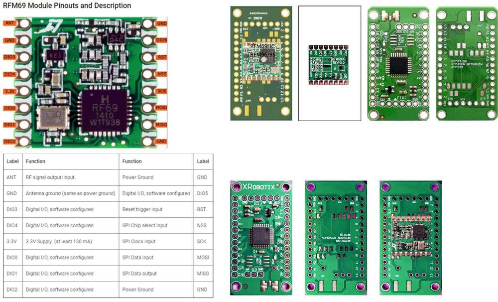
@tbowmo I am using Sensebender Micro on an ATMega328p Barebones with internal 8MHz and RFM69 working good. Since I don't have quartz connected on PB6 and PB7, I would like to use these ports. I tried from 14 to 21 but unable to flash my led (connected to PB6).
With Minicore: PB6 and PB7 are 20 and 21 respectively.
With Sensbender Micro, what are the ports? (if they exist)
SuperNinja
Posts
-
💬 Sensebender Micro -
Compilation error when using LowPower.h library with MySensorsgreat thank you for your answer! :+1:
-
Compilation error when using LowPower.h library with MySensorsHi all,
I would like to put my node on deepsleep (328p + rfm69hcw + battery):- I first used the
sleep ()but I did not go lower than 3.7mA - I saw on this topic https://forum.mysensors.org/topic/1478/rfm69-sleep-mode?_=1610979868641 that we could go lower with
LowPower.hwith
LowPower.powerDown (SLEEP_8S, ADC_OFF, BOD_OFF);-
I succeeded with going down to 17µA BUT ONLY with the lowpowerlab libraries
-
if I include
LowPower.hin my MySensors sketch :
//===== RFM config =====
#define MY_RADIO_RFM69
#define MY_IS_RFM69HW //with H(CW)
#define MY_RFM69_NEW_DRIVER
#define MY_RFM69_FREQUENCY  RFM69_868MHZ
#define MY_SIGNAL_REPORT_ENABLED

#define MY_RFM69_IRQ_PIN 2
#define MY_RFM69_CS_PIN 10

//===== LOWPOWERLAB =====
#include <LowPower.h> //get library from: https://github.com/lowpowerlab/lowpower
//writeup here: http://www.rocketscream.com/blog/2011/07/04/lightweight-low-power-arduino-library/

#include <MySensors.h>

//========== TRANSMISSION ID ==========
#define CHILD_ID_RX_RSSI        (4)

//pr1: ===== vcc =====
#include <Vcc.h>                      //https://github.com/Yveaux/Arduino_Vcc
const float VccMin   = 0.0;           // Minimum expected Vcc level, in Volts.
const float VccMax   = 3.3;           // Maximum expected Vcc level, in Volts.
const float VccCorrection = 3.32 / 3.29; // Measured Vcc by multimeter 4.97 divided by reported Vcc 4.88
Vcc vcc(VccCorrection);
#define CHILD_ID_VCC        (10)

//pr2: ===== sleep =====
unsigned long SLEEP_TIME = 60000;           // Sleep time between reads (in milliseconds) 60000=1minute

//========== Initialize general MESSAGE ==========
MyMessage msgRxRSSI(CHILD_ID_RX_RSSI, V_CUSTOM);
MyMessage msgVcc(CHILD_ID_VCC, V_VOLTAGE);

//===================================
//=              BEFORE              =
//===================================
void before()
{

} //FIN de before

//===================================
//=              SETUP              =
//===================================
void setup() {//no need Serial.begin(115200)

}//FIN du SETUP
//==========================================
//=              PRESENTATION              =
//==========================================
void presentation()
{
  // Send the sketch version information to the gateway and controller
  sendSketchInfo("ATC_report & Vcc", "1.0");

  // Register all sensors to gw (they will be created as child devices)
  present(CHILD_ID_RX_RSSI, S_CUSTOM, "RX RSSI");
  present(CHILD_ID_VCC, S_MULTIMETER, "Vcc");

} // FIN de PRESENTATION
//===================================
//=              LOOP               =
//===================================
void loop()
{
  // send messages to GW
  // retrieve RSSI / SNR reports from incoming ACK
  send(msgRxRSSI.set(transportGetSignalReport(SR_RX_RSSI)));

  Serial.print("Receive RSSI: ");
  Serial.println(  RFM69_getReceivingRSSI ());

  //pr1:========== send vcc ==========
  float v = vcc.Read_Volts();
  Serial.print("VCC = ");
  Serial.print(v);
  Serial.println(" Volts");

  float p = vcc.Read_Perc(VccMin, VccMax);
  Serial.print("VCC = ");
  Serial.print(p);
  Serial.println(" %");
  send(msgVcc.set(v, 1));

  Serial.println("Enter in sleep time ...");
  //pr1:===== sleep =====
  LowPower.powerDown(SLEEP_8S, ADC_OFF, BOD_OFF); //COMPILATION ERROR  : libraries\LowPower-master\LowPower.cpp.o: In function `__vector_6':

  //sleep(SLEEP_TIME);                         //WORK BUT :  go from 25mA to 3.7mA (not µA)
  //gw.sleep(8000);             // MysensorsV1 :  3.7mA

}// FIN de LOOP
I have this error:
Arduino: 1.8.13 (Windows 10), Card: "ATmega328, Yes (UART0), EEPROM retained, 328P / 328PA, BOD 2.7V, LTO disabled, External 16 MHz "
libraries \ LowPower-master \ LowPower.cpp.o: In function `__vector_6 ':
D: \ Documents \ Arduino \ SKETCH \ libraries \ LowPower-master / LowPower.cpp: 1190: multiple definition of `__vector_6 '
sketch \ moteino_MySensors_vcc_sleep_pr3.ino.cpp.o: D: \ Documents \ Arduino \ SKETCH \ libraries \ MySensors / hal / architecture / AVR / MyHwAVR.cpp: 79: first defined here
collect2.exe: error: ld returned 1 exit status
exit status 1
Compilation error for the ATmega328 card
Someone to help me ?
- I first used the
-
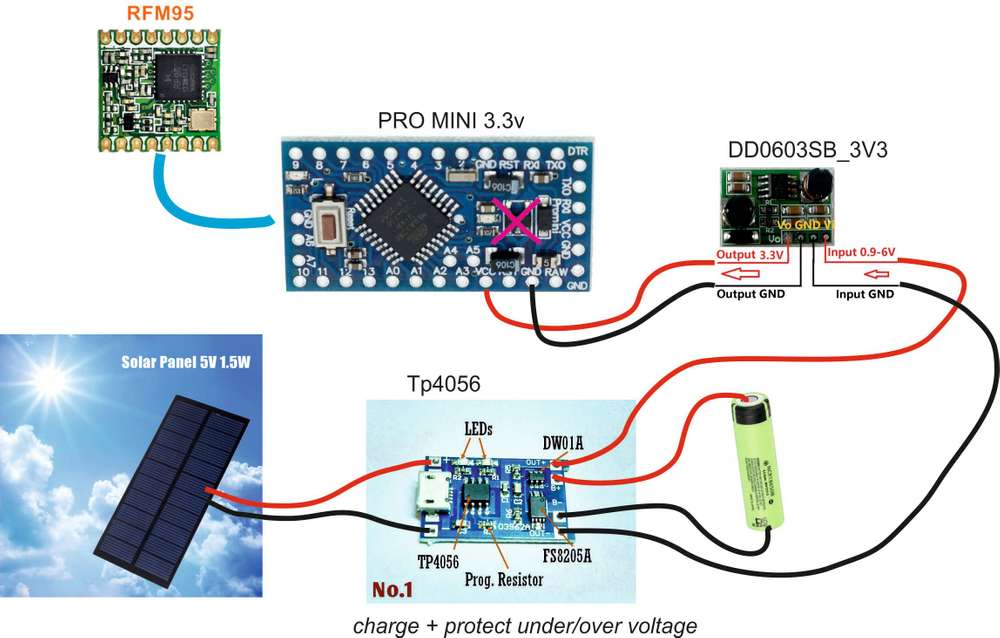
Need advice on solar powering with LiFePo4 battery@NeverDie yes the TP4056 is only valid for li-ion. The 18650 you can find so everywhere in new or "second hand" (laptop battery, hand vacuum cleaner ...) At first it was a cheap weather test, it has been in the garden for 4 years lol
I just took it apart to integrate it into MYSENSORS with RFM69.
@willemx , thanks i wanted to share something that works ;) , Indeed, lifepo4 is more attractive with its 3.2 -3.4v and the TP5000 with a negative point: a resumption of charge at 3.5v which seems a little high according to the testers. -
Need advice on solar powering with LiFePo4 battery
here is an example of realization which works for me (I have an RFM69).
I transmit temperature, humidity and pressure atmosphere all 30s and sleep. (BMP280 SHT30)
the TP4056: charges and protects the LI-ION against overvoltage and undervoltage (approx 2.7v)
There is surely to criticize or optimize the scheme: power of the solar panel, the battery, the buck Boost etc.
But in the state, it can transmit for 4 days of rain without sunshine (after a full charge in the sun). -
difference between encryption with personalization and simple password@Anticimex , @Anduril Thanks for this response
@evb great job, here is an easy to understand summary for beginners like me. Thanks -
difference between encryption with personalization and simple password@Anduril said in difference between encryption with personalization and simple password:
#define MY_RFM69_ENABLE_ENCRYPTION
@Anticimex
Interesting, I'm going to make a remote control for my gate with an RFM69HCW, obviously I don't want the signal to be sniffed and copied.I am new to MySensors, Is :
#define MY_RFM69_ENABLE_ENCRYPTION
#define MY_SECURITY_SIMPLE_PASSWD "testpass"
is simply enough?
What to add if not secure enough? -
Thanks for node-red-contrib-mysensors and a question regarding collections or arraysHi @Joost
did you try with the node-red-node-ui-table ?


[{"id":"7bd456cb.117438","type":"ui_table","z":"9e0024db.fa0ee8","group":"db0ce087.cc771","name":"","order":3,"width":0,"height":0,"columns":[],"outputs":0,"cts":false,"x":660,"y":4380,"wires":[]},{"id":"5766ed81.1001b4","type":"function","z":"9e0024db.fa0ee8","name":"","func":"msg.payload=[\n {\n \"Name\": \"Kazuhito Yokoi\",\n \"Age\": \"35\",\n \"Favourite Color\": \"red\",\n \"Date Of Birth\": \"12/09/1983\",\n \"Rating\": 5\n },\n {\n \"Name\": \"Oli Bob\",\n \"Age\": \"12\",\n \"Favourite Color\": \"red\",\n \"Date Of Birth\": \"12/08/2017\",\n \"Rating\": 2\n }\n]\nreturn msg;","outputs":1,"noerr":0,"initialize":"","finalize":"","x":530,"y":4380,"wires":[["7bd456cb.117438"]]},{"id":"96793ea3.29b8b","type":"inject","z":"9e0024db.fa0ee8","name":"msg","props":[{"p":"nodeId","v":"3","vt":"str"},{"p":"payload"},{"p":"port","v":"com66","vt":"str"}],"repeat":"","crontab":"","once":false,"onceDelay":"","topic":"","payload":"-666","payloadType":"str","x":390,"y":4380,"wires":[["5766ed81.1001b4"]]},{"id":"db0ce087.cc771","type":"ui_group","name":"log","tab":"db35bd74.691fe","order":1,"disp":true,"width":"12","collapse":false},{"id":"db35bd74.691fe","type":"ui_tab","name":"MySensors","icon":"dashboard","order":1,"disabled":false,"hidden":false}] -
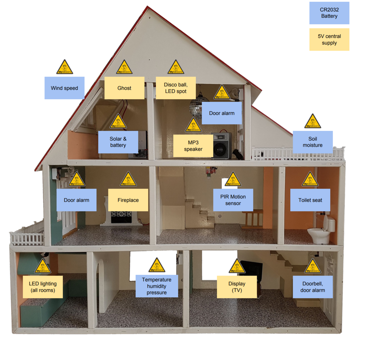
Dollhouse project : need Node-Red Controller flowHi all,

I found the Dollhouse project very concrete and representative of everything you need for a smart home.
I am interested in the Controller part which is made thanks to Node-Red and the node-red-contrib-mysensors plugin, however I don't see the Flow in the folder, nor in the Github repository?@Yveaux (or someone else build this project) could you add it to your repository?
Thank you in advance
Chris
-
RFM69HCW beginning of a newbie with ATMEGA328PI come back here with good news :laughing:
Here I succeeded in making communicate the Node and the Gateway.
At first I did not have a Parent and I understood that this was because I had not given a hard NODE_ID.
To remedy this I downloaded the excel: Windows GUI / Controller for MySensors which automatically assigns the NODE_lDSo if I resume my start test installation:
- a Node RFM69HCW + ATmega 328p with the following sketch:
/* This is an example that demonstrates how to report the battery level for a sensor Instructions for measuring battery capacity on A0 are available here: http://www.mysensors.org/build/battery */ // Enable debug prints to serial monitor #define MY_DEBUG //#define MY_DEBUG_VERBOSE_SIGNING // RFM config #define MY_RADIO_RFM69 #define MY_RFM69_NEW_DRIVER #define MY_RFM69_FREQUENCY RFM69_868MHZ #define MY_SIGNAL_REPORT_ENABLED #define MY_RFM69_ATC_TARGET_RSSI_DBM (-85) //#define MY_RFM69_ENABLE_ENCRYPTION //#define MY_DEBUG_VERBOSE_RFM69 //#define MY_RFM69_NETWORKID 101 #define MY_RFM69_IRQ_PIN 2 #define MY_RFM69_CS_PIN 10 #define MY_IS_RFM69HW //========== LED ========== //#define MY_DEFAULT_TX_LED_PIN 9 // the PCB, on board LED #define MY_DEFAULT_RX_LED_PIN 9 // Receive led pin // Set blinking period #define MY_DEFAULT_LED_BLINK_PERIOD 300 // Inverses the behavior of leds #define MY_WITH_LEDS_BLINKING_INVERSE //========== ANALOG INPUT ========== //#define BATTERY_SENSE_PIN = 0; // select the input pin for the battery sense point //int oldBatteryPcnt = 0; //========== DIGITAL INPUT ========== //#define DIGITAL_INPUT_SENSOR 3 // The digital input you attached your motion sensor. (Only 2 and 3 generates interrupt!) //#define CHILD_ID 1 // Id of the sensor child //========== NODE ID ========== //#define MY_NODE_ID 1 //#define MY_NODE_TYPE "NODE" #include <MySensors.h> // ID of the sensor child #define CHILD_ID_UPLINK_QUALITY (0) #define CHILD_ID_TX_LEVEL (1) #define CHILD_ID_TX_PERCENT (2) #define CHILD_ID_TX_RSSI (3) #define CHILD_ID_RX_RSSI (4) #define CHILD_ID_TX_SNR (5) #define CHILD_ID_RX_SNR (6) // Initialize general message //MyMessage msgUplinkQuality(CHILD_ID_UPLINK_QUALITY, V_CUSTOM); //MyMessage msgTxLevel(CHILD_ID_TX_LEVEL, V_CUSTOM); //MyMessage msgTxPercent(CHILD_ID_TX_PERCENT, V_CUSTOM); MyMessage msgTxRSSI(CHILD_ID_TX_RSSI, V_CUSTOM); //MyMessage msgRxRSSI(CHILD_ID_RX_RSSI, V_CUSTOM); //MyMessage msgTxSNR(CHILD_ID_TX_SNR, V_CUSTOM); //MyMessage msgRxSNR(CHILD_ID_RX_SNR, V_CUSTOM); //=================================== //= SETUP = //=================================== void setup() { }//FIN du SETUP //========================================== //= PRESENTATION = //========================================== void presentation() { // Send the sketch version information to the gateway and controller sendSketchInfo("ATC_report", "1.0"); // Register all sensors to gw (they will be created as child devices) //present(CHILD_ID_UPLINK_QUALITY, S_CUSTOM, "UPLINK QUALITY RSSI"); // present(CHILD_ID_TX_LEVEL, S_CUSTOM, "TX LEVEL DBM"); //present(CHILD_ID_TX_PERCENT, S_CUSTOM, "TX LEVEL PERCENT"); present(CHILD_ID_TX_RSSI, S_CUSTOM, "TX RSSI"); // present(CHILD_ID_RX_RSSI, S_CUSTOM, "RX RSSI"); // present(CHILD_ID_TX_SNR, S_CUSTOM, "TX SNR"); // present(CHILD_ID_RX_SNR, S_CUSTOM, "RX SNR"); } //=================================== //= LOOP = //=================================== void loop() { // send messages to GW //send(msgUplinkQuality.set(transportGetSignalReport(SR_UPLINK_QUALITY))); //send(msgTxLevel.set(transportGetSignalReport(SR_TX_POWER_LEVEL))); //send(msgTxPercent.set(transportGetSignalReport(SR_TX_POWER_PERCENT))); send(msgTxRSSI.set(transportGetSignalReport(SR_TX_RSSI))); // retrieve RSSI / SNR reports from incoming ACK // send(msgRxRSSI.set(transportGetSignalReport(SR_RX_RSSI))); // send(msgTxSNR.set(transportGetSignalReport(SR_TX_SNR))); // send(msgRxSNR.set(transportGetSignalReport(SR_RX_SNR))); // wait a bit wait(10000); }// FIN de LOOP ///* void receive(const MyMessage &message) { Serial.print("Message recu pour le capteur :"); Serial.print(message.sensor); Serial.print(", Nouveau statut : "); Serial.println(message.getBool()); } //*/- a Gateway RFM69HCW + ATmega 328p with the following sketch, connected to the PC win10 on a USB socket (thanks to an FTDI) :
/* DESCRIPTION The ArduinoGateway prints data received from sensors on the serial link. The gateway accepts input on serial which will be sent out on radio network. The GW code is designed for Arduino Nano 328p / 16MHz */ // Enable debug prints to serial monitor #define MY_DEBUG //#define MY_DEBUG_VERBOSE_SIGNING // RFM config #define MY_RADIO_RFM69 #define MY_RFM69_NEW_DRIVER #define MY_RFM69_FREQUENCY RFM69_868MHZ #define MY_SIGNAL_REPORT_ENABLED //#define MY_RFM69_ATC_TARGET_RSSI_DBM (-85) //#define MY_RFM69_ENABLE_ENCRYPTION //#define MY_DEBUG_VERBOSE_RFM69 //#define MY_RFM69_NETWORKID 101 #define MY_RFM69_IRQ_PIN 2 #define MY_RFM69_CS_PIN 10 #define MY_IS_RFM69HW // Enable serial gateway #define MY_GATEWAY_SERIAL /* // Define a lower baud rate for Arduinos running on 8 MHz (Arduino Pro Mini 3.3V & SenseBender) #if F_CPU == 8000000L #define MY_BAUD_RATE 38400 #endif // Enable inclusion mode #define MY_INCLUSION_MODE_FEATURE // Enable Inclusion mode button on gateway //#define MY_INCLUSION_BUTTON_FEATURE // Inverses behavior of inclusion button (if using external pullup) //#define MY_INCLUSION_BUTTON_EXTERNAL_PULLUP // Set inclusion mode duration (in seconds) #define MY_INCLUSION_MODE_DURATION 60 // Digital pin used for inclusion mode button //#define MY_INCLUSION_MODE_BUTTON_PIN 3 */ //========== LED ========== //#define MY_DEFAULT_TX_LED_PIN 9 // the PCB, on board LED #define MY_DEFAULT_RX_LED_PIN 9 // Receive led pin // Set blinking period #define MY_DEFAULT_LED_BLINK_PERIOD 300 // Inverses the behavior of leds #define MY_WITH_LEDS_BLINKING_INVERSE #include <MySensors.h> //=================================== //= SETUP = //=================================== void setup() { // Setup locally attached sensors } //========================================== //= PRESENTATION = //========================================== void presentation() { // Present locally attached sensors } //=================================== //= LOOP = //=================================== void loop() { // Send locally attached sensor data here }- On the PC the execution of the Controller program: Windows GUI / Controller for MySensors.
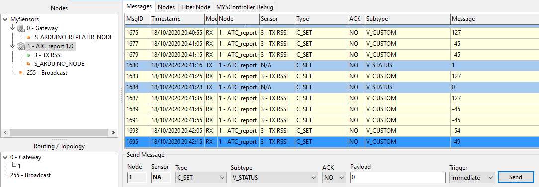
Which give :

We can see in sky blue, the sending of the state of a virtual "Motion" sensor from the Gateway to the Node (adjustable at the bottom of the interface).
The other V_CUSTOMs are the RSSI of the RFM69 transmition stage.
Oddity: after receiving the state of the Motion sensor, sent by the Gateway, the Node transmits a value of 127 ??
Everything works, out of the box, you just had to know how to start with the configuration of the RFM69HCW, thank you @scalz
The second step is to replace the Win10 Controller with a Node-Red Controller.
I already have a Node-Red server with its Dashboard running on an RPI 3B.
I found "node-red-contrib-mysensors" but it still seems blurry to me (sorry I learn fast but you have to explain myself a long time) :yum:I think I'll open another Topic or continue on the original node-red-contrib-mysensors, Topic.
-
RFM69HCW beginning of a newbie with ATMEGA328P@scalz said in RFM69HCW beginning of a newbie with ATMEGA328P:
you could also show your sketch, and logs so people can help you.
Thank you for your help, precisely, I did not have a sketch to start which corresponds to my material which is however basic.
yes for the "new driver". i test your example. -
RFM69 using Mysensors 2.3.2@mfalkvidd I'm sorry to have duplicated my request, as you were using RFM69, I thought you had a configuration already done.
HCWs (HW) are so popular that I thought someone had a working config, so I could start developing my nodes / gateway with the last libraries and current driver. -
RFM69 using Mysensors 2.3.2@mfalkvidd Hi, I am desperately looking for a configuration for the RFM69HCW with an ATmega328p.
- I am lost between the old library <2.0 and the new one
- the old RFM69 driver and the new one
can you give me an example configuration? or a simple Sketch node to beginning ?
-
RFM69HCW beginning of a newbie with ATMEGA328PRe: [SOLVED] Newbie trying to get RFM69HCW working with ATMEGA328P
Hi all,
I continue this topic here to have more details on the beginning with MySensors- I have 2 moteino (clone) with RFM69HCW 868MHz and ATMEGA328p at 3.3v
- both are connected to the pc with FTDIs on 2 USB sockets, and therefore 2 ARDUINO IDE windows open.
- RFM69HCW connections are: SCK: 13, MISO: 12, MOSI: 11, CS: 10, IRQ: 2
- 1 integrated blue led out of 9
What I managed to do: use an example from the RFM69 library of lowPowerLab = the 2 modules communicate well.
What I would like to do with MySensors:
- correctly initialize my modules (I saw that there is an RFM69_new_driver): define the RFM69HCW, the pins, the frequency, the ATC mode ...
- do a first sketch of "hello world!" that the Node transmits to the Gateway.
I have read a lot of examples and it is very confusing for me because there are different ways to initialize the RFM69. Some are obsolete, others don't work, or are only made for HW. Anyway, can you help me create my first start-up sketch to get started on a solid foundation.
-
Which radio / wireless module to choose? Please recommendIndeed, now that you say it, it looks a lot like Moteino.
Anyway, I can't wait to see my first "hello world" appear on my screens. I will see later for the OTA with double bootloader, that will be the icing on the cake :) -
Which radio / wireless module to choose? Please recommend@tssk said in Which radio / wireless module to choose? Please recommend:
Arduino Pro Mini 3.3V + DHT22 or BME280 + 433/868 radio module
Hello, I am going to take my first steps with the MySensors library. I found this Mega328p + RFM69HCW kit:
https://www.aliexpress.com/item/33006101437.html?spm=a2g0s.9042311.0.0.3f774c4dIx4PVw

I find this development board interesting:
- accepts many RFMs
- possibility of soldering an antenna wire or SMA or uFL connector.
- No voltage indicator led, but a 3.3v regulator (which can be unsoldered). A blue led connected to a gpio.
- known 328p microcontroller (arduino compatible)
- connector for FTDI
- possibility of soldering an additional FLASH ROM
- many gpio available
I am waiting for the schematics and software included, from the seller to say more. For now, the blue led flashes once powered on, but no return to the serial link ... I will post more news if the topic is requesting ;)
