Windows GUI/Controller for MySensors


  • Admin

    Hi all,

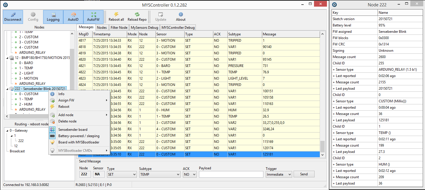
    I've been working on this project since some time, basically it's a GUI for controlling/updating/debugging a network of MySensors nodes. OTA functionality is supported via MYSBootloader - read posts for further instructions/troubleshooting or PM.

    link updated: MYSController Version 1.0.0.3316 released

    New features:

    • support OTA FW update Sensebender board
    • metric/imperial system I_CONFIG
    • save nodes

    Update via update button in MYSController or download here.

    MYSController_0_1_2_282.png


  • Plugin Developer

    @tekka
    This is very, very cool! It connects to Ethernet or does it also do serial?


  • Admin

    both. in my setup i'm using a serial over tcp approach (NAS: serial gateway & ser2net)- fw loading is substantially faster and more stable compared to the ethernet gateway.


  • Plugin Developer

    @tekka
    Very nice approach, this could also work on other boxes where serial interfaces are not exclusively opened.


  • @tekka

    You plan to share this, or provide the sources?

    It looks indeed verry nice 😉


  • Good work man! im make a controller in .net!

    http://clip2net.com/s/3aGJdvY


  • Admin

    @ericvdb yes, I will provide a link soon
    @ch3b7 cool 👍 , are you also implementing tcp connections?


  • yes but at now im not have a ethernet shield right now =( and i need to work with the optiboot/OTA bootloader part and dont know where find that part "request" "send" all that info. sorry my bad english im from argentina.!


  • Hero Member

    Yes, looks really nice!

    Seems to be written in TK so cross-platform, even better!


  • Hero Member

    Wow...really nice. Cant wait to give it a go!


  • wow, this is something!
    would really love to set this up at home!
    i also can't wait for your link to appear, really exited !


  • Yeah, really looks nice!
    Can't wait too for the link and more info about de OTA bootloader.
    I'm making some industrial opensources sensor based on MySensor and my current bootloader don't have an OTA Bootloader. So it would be greate with your Bootloader and your application!


  • Nice.... Following


  • This looks very interesting. Seems like it will make remote debugging easy, ie can run this on a PC at home and RDP into it.


  • Also Following. Very keen to try this!


  • Hero Member

    Will this program act like a controller (take the place of Vera?) and handle automation logic?


  • Admin

    hi all,

    here is the first alpha version of the MYSController (I changed the name).

    http://goo.gl/9DCWNo

    There are still lots of things that need to be done and some bugs :), but feel free to give it a try. I included the modified bootloader (flash according to the settings in the fuses.txt file) and two example .hexs for testing/uploading. From my experience, the OTA works better/faster using the serial gateway.

    Cheers,
    tekka


  • Got it working first try! Can see data coming back from my Temp and Hum sensors!

    Looks like a great tool.

    Thank you!


  • Hero Member

    @tekka

    here is the first alpha version of the MYSController

    👍

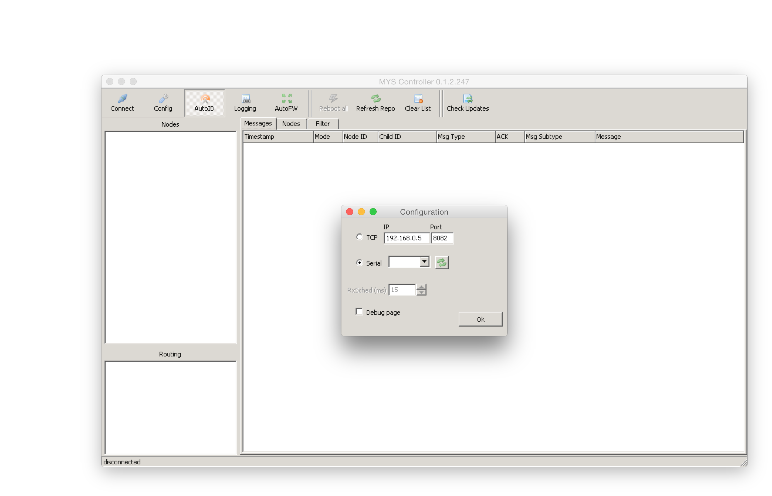
    Saw it was a Windows executable but did give it a try on Linux:

    wine MYSController.exe
    

    And the GUI comes up nicely!

    I can not select the serial port yet, so could not test it further, likely have to do some mapping in wine.


  • Admin

    Yepp.. GUI comes up on mac using wine as well. Will try tomorrow when I have an Arduino nearby.

    Screen Shot 2015-01-22 at 23.50.37.png


  • is it possible tu use the ota bootloader on 8Mhz?


  • Admin

    For OTA should be ok, for AVRDUDE not tested


  • OK, Thank's!

    The GUI doesn't work on mac with wine. The program is running good but do not recognize the usb device (even with a symbolic link to wine,...). Is it possible to get the program on mac?


  • Admin

    @Tibus
    I will look into that. Meanwhile, can you try to link the serial gateway to localhost (e.g. ser2net or socat) and connect via tcp?


  • ok, I'll try that. Really looking forward to play with it ;D


  • Hero Member

    I can not select the serial port yet, so could not test it further, likely have to do some mapping in wine.

    Took some time to find out but after:

    • Adding a mapping from the Linux serial port to the Wine dosdevice configuration:
      ln -s /dev/serial/by-id/usb-FTDI_FT232R_USB_UART_* ~/.wine/dosdevices/COM3

    • Adding to ~/.wine/system.reg:

        [Hardware\\Devicemap\\Serialcomm] 1231984861
        @=""
        "Serial0"="COM1"
        "Serial1"="COM2"
        "Serial2"="COM3" 
    

    I could start MYSController.exe and select COM3 and get:

    File_not_open.png

    But after pressing OK things look to work however:

    Gateway_startup_complete.png

    @tekka : Thanks!


  • Admin

    @daulagari thanks for the workaround. Success with OTA?


  • Hero Member

    Doing OTA did work once but trying a second time did not work out yet.

    I found that it is important the user that runs "wine MYSController.exe" must have access to the port ~/.wine/dosdevices/COMx links to:

    $ ls -als /dev/serial/by-id/usb-FTDI_FT232R_USB_UART_*
    0 lrwxrwxrwx 1 root root 13 25 jan 09:38 /dev/serial/by-id/usb-FTDI_FT232R_USB_UART_A9SZN99X-if00-port0 -> ../../ttyUSB0
    

    Is not good ("root root"), I changed the link to to:

    $ ls -asl /dev/ttyUSB0 
    0 crw-rw---- 1 root dialout 188, 0 25 jan 11:34 /dev/ttyUSB0
    

    In the debug log I see the 0;0;3;0;14;Gateway startup complete. message but no messages from the sensor.

    Looks like the "File not open." window I am getting and:

    fixme:comm:set_queue_size insize 4096 outsize 0 unimplemented stub
    

    I am seeing on the command line has something to do with it.

    NB: Seems like the GUI is programmed using TK. How about compiling it for Linux?


  • Admin

    @daulagari
    interesting, do you get the "File not open" message with AutoFW disabled? Also, what happens if you reboot the gateway several times (reset button), does the "Gateway startup complete" message re-appear? I recall that I had problems with OTA with the debug-mode enabled in config.h, the gateway kept freezing when sending OTA messages.
    The controller is written in lazarus/fpc - porting to mac or *nix should be straight forward, I'll have a look.


  • Hero Member

    I have AutoFW disabled.

    The funny thing is that things do not work at all if I do not get the "File not open" error.
    No, rebooting the gateway does not make the "Gateway startup complete" message re-appear.

    Did watch the serial port using interceptty and see data is passed so it seems like Wine is not passing it.


  • Hero Member

    Did do some more experimenting using a sort of Ethernet gateway (actual the relayed Serial gateway data) and see that MYSController.exe can connect but once it prints the first data it gives the "File not open." error and no further data is printed.

    So it does not look like a serial port issue but something else.

    Did not know Lazarus but it looks pretty good!


  • Admin

    @daulagari
    ok, I could reproduce the error which seems to appear in connection with scrambled data from the gateway (during the gateway startup). If you press the dis- and connect-button a few times once the error appears, all pending messages will be processed and the controller should resume.


  • Admin

    New version available with bug fixes 0.1.2.256:

    • "File not open" error fixed
    • Display errors fixed
    • Mac users: use wine to run program, no remapping of serial ports necessary - use e.g. /dev/ttyUSB0 in config window

    To update hit the update button or download here.


  • Admin

    Great, I'll add a link from the main site to your project.


  • Hero Member

    @tekka : Thanks, things work now fine! 👍


  • Any source code?


  • Hero Member

    @tekka Hi, Chrome is blocking the download of the Windows GUI/Controller zip archive for being "harmfull". any clue?


  • Admin

    @AWI My guess is because of the upx-packed executable (MYSController.exe) in the archive being recognized as false positive.


  • Admin

    @ch3b7 said:

    Any source code?

    Yes, I will provide the source code in the nearest future.


  • Hello team, thanks for the great job. This tool is very useful.
    however, I don't understand how the tool can snif. I guess, that I have to connect an arduino in serial ( I use the tool in a VM)... but with which sketch ? a gateway sketch...I think I missed something, but if somebody can elaborate a little bit. thanks


  • You need upload the serialgateway sketch to the arduino connected with the nrf24 the n connect the usb to pc and select the correct com port in the program


  • " It works in connection with the modified optiboot/OTA bootloader mentioned in a previous post. "

    can someone link to that post? I couldn't find it
    Thanks


  • You add ethernet support? Im add ethernet support in my program in .net its work good.


  • Admin

    @mvader this is the MYSBootloader from the library.


  • @tekka said:

    @mvader this is the MYSBootloader from the library.

    okay thanks!


  • Hero Member

    @tekka cool software! btw the sorting of the child sensors in the tree could be optimized.
    Right now the nodes are sorted like string instead of numbers:

    0 - ...
    1 - ...
    10 -
    11 -
    ...
    2 -
    21-
    ...


  • @tekka said:


    To update hit the update button or download here.


    Chrome blocks the download since it is "malicious".


  • Admin

    @samppa read my previous post::

    @AWI My guess is because of the upx-packed executable (MYSController.exe) in the archive being recognized as false positive.

    I didn't face a warning with IE or Firefox, but indeed, Chrome reports it.


  • Admin

    @Heinz thanks. I will add the number sorting in the next build.


  • Greetings Tekka,

    I am teaching myself programming while learning about the NRF24L01+ and various controllers and sensors. I have tried to download several free software controllers but yours is the only one that was straightforward enough for me to be successful. I have used it to monitor communication to and from my gateway but I am at a loss as to how to use your creation as a controller. It is the most wonderful tool for visualizing and debugging node-to-gateway communications because of the exceptional work you have done translating the command codes into real command words.

    Is there a way to input data through your GUI or is it best used as an output device? If input is accepted, would you be so kind as to elaborate on the subject enough to get me moving?

    Respectfully - Baran


  • Right click on a node and click Send Msg:

    upload-470b8000-35d1-49b5-8917-27fb9cf5934f


  • Thanks Eric - Way too cool!


  • Hi.
    I try your project ..and find problem in my side..
    I use MCU with USB - UART converter what possible set speed max 38kBps .. is possible in your MYSController set lower speed ??
    I thinks that you now use 115200 ..

    regards.


  • Contest Winner

    I'm looking some days into this topic, although I found not the time to test your very good looking software - The issue mentioned by dzairo would also be important for me. As I run my nodes at 8MHz I cannot use the default 115200kbps and use (also) 38kbps - so it would be important for me to change the BAUD rate too.

    Anyways - nice work!


  • ... some other problem is if you want run MCU in 3.3V then not possible use higher frequency .. then all use internal 8 Mhz RC oscillator and maximum speed is 38k ..
    this is reason why use 38k ..

    best regards.


  • Admin

    @Dirk_H , @dzairo: yup, will include this option in the next update. Thanks for reporting.


  • Thank you for this excellent work. I look forward to using it in my network. I just have a couple questions regarding setting up the GUI. I've read through this thread several times, but still have a couple of gaps in my understanding.

    1. Is the gateway that interfaces with the GUI an additional gateway which listens to, and sends node messages and updates? That is, additional to one that is interfaced with the controller (in my case a serial gateway connected to a Vera controller)?

    2. If my the answer to my first question is, yes, it is an additional gateway, is the code defining the operation different such that is does not interfere with the 'true' gateway? Or is the code the same (standard serial gateway sketch) but simply does not interfere?

    3. Do the nodes require the MYSBootloader in order to show up in the 'messages' tab, or will 'messages' tab show all node traffic regardless of bootloader? Of course for over the air (OTA) sketch updates it needs the MYSBootloader.

    4. Are these the correct steps to setup operation:

    a) download and extract the files.

    'b) place the bootloader folder into /arduino/hardware path such that the MYSBootloader and the associated boards show up in the 'tools->boards' menu.

    c) connect an Arduino with the gateway sketch to a computer using a USB cable (for the serial connection).

    d) run MYSController.exe (on windows) and select the COM port of the serial gateway in the configuration.

    e) hit connect and node traffic will show up in the 'messages' tab.

    If this is correct (and now that I write it down) it seems pretty straightforward, but I didn't see it explicitly described elsewhere. Sorry to be such a beginner, and thanks for straightening me out if I'm incorrect in any step.


  • Admin

    @therik said:

    Is the gateway that interfaces with the GUI an additional gateway which listens to, and sends node messages and updates? That is, additional to one that is interfaced with the controller (in my case a serial gateway connected to a Vera controller)?

    No, but certainly a good idea to look into.

    Do the nodes require the MYSBootloader in order to show up in the 'messages' tab, or will 'messages' tab show all node traffic regardless of bootloader? Of course for over the air (OTA) sketch updates it needs the MYSBootloader.

    No, the MYSBootloader is required for OTA updates with MYSController or compatible controllers.

    Are these the correct steps to setup operation:

    a) download and extract the files.

    'b) place the bootloader folder into /arduino/hardware path such that the MYSBootloader and the associated boards show up in the 'tools->boards' menu.

    c) connect an Arduino with the gateway sketch to a computer using a USB cable (for the serial connection).

    d) run MYSController.exe (on windows) and select the COM port of the serial gateway in the configuration.

    e) hit connect and node traffic will show up in the 'messages' tab.

    Yes, that's pretty much it. Copying the bootloader directory is only needed for updating to MYSBootloader via ISP.


  • Admin

    @Dirk_H , @dzairo BAUD option included in the latest release. Update via software or here.


  • @tekka Hello, I check your great software and do my first steps with mySensors.

    It looks very amazing!

    Here are my first comments:

    1. I must program the MYSBootloader with the H-fuse setting H:0xD8 (2048 word), the value H:0xDE (in your fuses.txt) or H:0xDA (in your boards.txt) didn't work for me.
    2. The blink.hex seems to be the normal blink sketch, it didn't have nrf24 functionality. Needs a local hardreset to flash other firmware.
    3. The Arduino IDE (with the enhanced boards.txt) isn't able to program a firmware with the MYSBootloader - think this results in the higher baud rate (115200 vs. 57600) and my case to have the Arduino running in a VM !?
    4. The update function in MYSController isn't working because it needs a proxy configuration (not imported).
    5. I got a warning sign on the nodes-tree, don't know what it mean, but node is working (no info in the context menu).
    6. The interrupt line of the ner24L01 isn't needed.
    7. A right click in the open context menu ( e.g. on clear firmware) forces a software error.
      8 ) After connecting the Serial GW the MYSController doesn't responce for a while (searching for nodes?) Maybe a background task or an indicater would be a idea ?!
      9)On XP (or XP style) a selected row in the mesages or nodes tab is not readable - the selection is in dark blue, the text in black.

    It should be possible to use the MYSBootloder (.hex) without changes also for 8Mhz nodes (internal RC L:0xE2), OTA only.
    The SPI is independent from the clock, Uart is not used, delays are 2 times longer but this should be no problem.

    Is there a scenario to keep your MYSController connected and have the mash working at the same time?
    For example, with a gateway connected at Raspberry PI and a TCP connection from MYSController to the RPI? Or with two gateways ?

    Looking forward for the next features :-),
    regards Pit


  • Admin

    @pit007 Thanks for your feedback.

    1. I must program the MYSBootloader with the H-fuse setting H:0xD8 (2048 word), the value H:0xDE (in your fuses.txt) or H:0xDA (in your boards.txt) didn't work for me.

    Ups, this is a mistake in the fuses.txt file, I will update that. The settings in the boards.txt are correct.
    The MYSBootloader 1.0 is 1834 bytes in size, therefore 0xDA works (1024W), but 0xD8 (2048W) is also ok (assuming you are programming the atmega328p). All calls are relative, and the MCU skips invalid commands (0xFF) until it starts parsing at 0x7800.

    1. The blink.hex seems to be the normal blink sketch, it didn't have nrf24 functionality. Needs a local hardreset to flash other firmware.

    yep, correct 🙂

    1. The Arduino IDE (with the enhanced boards.txt) isn't able to program a firmware with the MYSBootloader - think this results in the higher baud rate (115200 vs. 57600) and my case to have the Arduino running in a VM !?

    With MYSBootloader 1.0 you can only program a firmware with MYSController or similar tools. I'm currently working on a dual bootloader that includes OTA and Arduino IDE/AVRDude programming.

    1. The update function in MYSController isn't working because it needs a proxy configuration (not imported).

    Hmm, I assume you are referring to the check for updates function (automatically triggered after startup)? I will look into that.

    1. I got a warning sign on the nodes-tree, don't know what it mean, but node is working (no info in the context menu).

    The warning sign means no version/type information received. This information is sent during MYSBootloader startup, but not with conventional (e.g. optiboot) bootloaders.

    1. The interrupt line of the ner24L01 isn't needed.

    The communication is entirely controlled by the gateway - and yes, the interrupt pin is not used in the current gateway setup.

    1. A right click in the open context menu ( e.g. on clear firmware) forces a software error.

    Please send a screenshot to myscontroller@gmail.com

    8 ) After connecting the Serial GW the MYSController doesn't responce for a while (searching for nodes?) Maybe a background task or an indicater would be a idea ?!

    Please check the debug tab: any truncated messages or error flags after startup?

    1. On XP (or XP style) a selected row in the messages or nodes tab is not readable - the selection is in dark blue, the text in black.

    ok, will look into that.

    It should be possible to use the MYSBootloder (.hex) without changes also for 8Mhz nodes (internal RC L:0xE2), OTA only.
    The SPI is independent from the clock, Uart is not used, delays are 2 times longer but this should be no problem.

    Yes, 8Mhz should work, but ideally you recompile the bootloader with F_CPU set to 8 Mhz for correct delay timings.

    Is there a scenario to keep your MYSController connected and have the mash working at the same time?
    For example, with a gateway connected at Raspberry PI and a TCP connection from MYSController to the RPI? Or with two gateways ?

    Not yet, but I have some ideas...

    Have fun


  • Hi and thanks for a cool piece of software!

    I finally got around to soldering an ethernet gateway and decided to give this a spin. It worked like a charm for a while but now I get this error everytime any message goes through the gateway to Vera:

    myscontroller error.PNG

    OS is 32-bit Windows 7

    I can only get rid of this behaviour if I delete the configuration settings file and start over. It seems it only happens if I have logging enabled and exit the program and restart it.

    I'll have to start playing with the bootloader soon to get the OTA capabilities.


  • Hi.
    Just one idea .. your tools is very good .. why not add more better function ..
    1.If not received data from sensor more than predefined time then send email or tweet .. etc. for example using https://www.pushingbox.com/
    2. Make server version .. for web interface ..
    I thinks .. is possible order in TESCO cheap windows 8.1 tablet in price 90Euros ..
    one or two year later then will be possible buy in price around 50 euros .. why not use this platform?
    I use ASUS with USB serial port and work good .. if make easy uart to wifi (esp8266) converter then can work directly with wifi..


  • Admin

    @slarti I've seen this error if the log file is exclusively opened somewhere else. Try deleting or renaming the current logfile and restart the MYSController. I will change the log file handling in a upcoming release.


  • Admin

    @dzairo certainly an interesting idea! Please have a look at one of the discussed home automation solutions - there you can even define more complex scenarios.


  • yes.. I just that user use RPi etc hardware solution .. but in fact
    is possible buy tablet .. complete solution : standard windows 8.1 , LCD , battery .. wifi , bluetooth .. CE .. why not use this platform ..
    give link for - home automation solution..

    regards..

    PS: you can see , I my self make similar software for windows ..but more easy .. and why not use windows core for server , database .. etc ..


  • @tekka This GUI is great help especially for beginners like me who don't understand what the serial messages mean! You extract all the information so well and so beautifully.
    Hope its not too much to ask, but may I take a look at the source code? Because I need to know the method you used to extract the messages, as well as tying the data to the proper fields. I somehow need to push all of these data to the proper fields in my database and I'm stuck at deciphering the messages being received. Thanks in advance and cheers!


  • Contest Winner

    This is a nice tool. Good work! Is there any possibility to get support for all the message types on the development branch as well?


  • Admin

    @Anticimex Thanks 🙂 Yes, I in the upcoming release.


  • Hi.
    One idea .. FIFO buffer for outgoing message..
    low power relay node .. if use bi stable relay then is possible to power only from battery .. but radio must go to sleep.. then wake up every 5 or 10 second .. and ask gateway for new command ..
    node just if wake up then waiting for example 0,5 sec for incoming message .. if not received then go sleep ..
    gateway wait for node .. and if got command in FIFO for this node then send message ..
    just idea..


  • Admin

    @dzairo excellent idea, this will be implemented in the .276 release. Thanks


  • Hi.
    ...ehm , in Windows is possible use database and install web server .. you have idea use this?
    database is good way , pls try thinking about my idea using cheap windows tablet as controller , by serial port (usb) or lan (wifi ..etc) . .. problem is that tablet memory is not good for many write cycle .. but this is possible solve ..
    best regards


  • Hi Tekka,
    Great tool and SO useful for debugging.
    I have MYSController running under Wine on Linux Mint with no problems.

    I do have one small issue though. I have a serial gateway that reports to Domoticz on my Mint PC. This works fine and MSController connects fine. When I tried to move my gateway to a remote installation of Domoticz on a Raspberry Pi (same network) MSController cannot see it if I try to connect by TCP. I hope it's just something silly like port no. or something, but any ideas?

    Many thanks


  • Admin

    @blackdog65 You will have to pipe the serial gateway via tcp:port with e.g. ser2net.


  • @tekka WOW! I thought that was going to be SO difficult... but it took 10mins total! Thank you very much... I'm good to go 😉


  • Admin

    For completeness, here are the MYSBootloader instructions for OTA updates via MYSController:

    1. Load gw sketch and connect arduino either via serial or ethernet port. No special bootloader needed for that part (i.e. standard optiboot bootloader will do the job).

    2. Add these lines to the boards.txt file in your Arduino IDE installation folder (located somewhere like C:/Program Files/Arduino/hardware/arduino/avr)

      proMYSBL16.name=ATmega328 external 16Mhz with MYSBootloader
      proMYSBL16.upload.tool=avrdude
      proMYSBL16.upload.protocol=arduino
      proMYSBL16.upload.maximum_size=30720
      proMYSBL16.upload.maximum_data_size=2048
      proMYSBL16.upload.speed=115200
      proMYSBL16.bootloader.tool=avrdude
      proMYSBL16.bootloader.low_fuses=0xF7
      proMYSBL16.bootloader.high_fuses=0xDA
      proMYSBL16.bootloader.extended_fuses=0x06
      proMYSBL16.bootloader.unlock_bits=0x3F
      proMYSBL16.bootloader.lock_bits=0x3F
      proMYSBL16.bootloader.file=MySensors/MYSBootloader.hex
      proMYSBL16.build.mcu=atmega328p
      proMYSBL16.build.f_cpu=16000000L
      proMYSBL16.build.board=AVR_UNO
      proMYSBL16.build.core=arduino
      proMYSBL16.build.variant=standard

      ######## settings for 8Mhz internal clock

      proMYSBL8.name=ATmega328 internal 8Mhz with MYSBootloader
      proMYSBL8.upload.tool=avrdude
      proMYSBL8.upload.protocol=arduino
      proMYSBL8.upload.maximum_size=30720
      proMYSBL8.upload.maximum_data_size=2048
      proMYSBL8.upload.speed=57600
      proMYSBL8.bootloader.tool=avrdude
      proMYSBL8.bootloader.low_fuses=0xE2
      proMYSBL8.bootloader.high_fuses=0xDA
      proMYSBL8.bootloader.extended_fuses=0x06
      proMYSBL8.bootloader.unlock_bits=0x3F
      proMYSBL8.bootloader.lock_bits=0x3F
      proMYSBL8.bootloader.file=MySensors/MYSBootloader.hex
      proMYSBL8.build.mcu=atmega328p
      proMYSBL8.build.f_cpu=8000000L
      proMYSBL8.build.board=AVR_UNO
      proMYSBL8.build.core=arduino
      proMYSBL8.build.variant=standard

    3. Copy MYSBootloader.hex (from MYSController/Bootloader folder) to the Arduino IDE installation folder C:/Program Files/Arduino/hardware/arduino/avr/bootloaders/MySensors/

    4. Restart Arduino IDE, choose under Tools | Board | ATmega328 external 16Mhz with MYSBootloader or Tools | Board | ATmega328 internal 8Mhz with MYSBootloader depending on your HW settings

    5. Connect USBasp to sensor node and select Tools | Burn Bootloader

    6. If everything worked well until here, you now have the MYSBootloader with the fuse settings from above burnt to your sensor node (16Mhz extXTAL or 8Mhz intRC, BOOTSZ 1024W, BOD 1V8).

    7. Please use the AVR fuse calculator to retrieve the individual fuse settings. If you need to change frequency, BOD or other settings, change the fuse settings based on the fuse calculator.
      Important: The MYSBootloader.hex file was compiled for 16Mhz oscillators but it should also work at 8Mhz. If you intend to go below 8Mhz, I highly recommend to compile the bootloader with adjusted frequency settings.

    8. Start MYSController, hit config and adjust settings (COM-Port & baud or IP address:port)

    9. Hit connect: Connection to gateway should be established (gateway answers with gateway ready message), the node should appear and request an ID & FW.

    10. Right-mouse click on that node, select assign FW, choose for example **TimeReporter ** (demo firmware included in the MYSController/Firmware folder). Then click reboot and wait until FW is uploaded and node boots.

    11. TimeReporter firmware reports every few seconds some values such as time, millis, and voltage.

    12. Custom firmware: compile your sketch and retrieve the generated .hex file (activate verbose mode in the Arduino IDE to get compiler messages and output path).

    13. Copy .hex file to MYSController/Firmware folder and edit firmware_config.csv file according to the existing lines.

    14. Hit Refresh Repo in MYSController and the newly copied firmware should appear in the Assign FW dropdown list, ready to be uploaded.

    Have fun 🙂


  • ..nice..
    .. and you try add new function what we talking above..? .. if make node with bi-stable relay battery powered only ..

    regards..


  • Contest Winner

    Hi,
    I have tried to use the GUI controller but I cannot get any output although it claims to be connected to my ethernet GW.
    I should mention that I run on the development branch. Perhaps there are changes that prevents your tool from acknowlegding my "development" gateway?
    EDIT: When connected through serial, it seem to work though. Perhaps the gw does not permit multiple connections on Ethernet. Nice! It barfs on my messages though but I guess it is because I run on dev and you have already stated that development branch support is "coming" so I don't worry about that.
    This is the output though in case you are interested:

    2015-03-10 20:31:02 ERROR: Truncated message, Msg=101;1;1;1;36;0
    101;1;1;1;36;0
    2015-03-10 20:31:14 RECV: 101;1;1;1;36;1
    101;1;1;1;36;1
    2015-03-10 20:31:14 ERROR: Truncated message, Msg=101;1;1;1;36;1
    101;1;1;1;36;1
    2015-03-10 20:31:20 RECV: 101;1;1;1;36;0
    101;1;1;1;36;0
    2015-03-10 20:31:20 ERROR: Truncated message, Msg=101;1;1;1;36;0
    101;1;1;1;36;0

  • Admin

    MYSController 0.1.2.276 and MYSBootloader 1.1 released:

    • send message upon RX (for battery-powered nodes)
    • bootloader commands (for MYSBootloader 1.1)
    • bugfixes

    Enjoy!


  • @tekka
    Thanks!
    Where can this be downloaded? Is that under an open source license, are sources available in github or something? If so, maybe someone would be willing to help with making it platform independent 🙂


  • @tekka very good job 👍 Thx !

    The ID change worked (but tried it only one time 🙂 A stesstest will follow ! )

    Next thing: Know how often a node send a package (or how long it like to sleep) and take this info to create a quality level and a warning if - i.e. after 3 times - there is no feedback from the node ?

    • Pit


  • The included TimeReporter (I don't know where to find the sketch) has a small problem.
    In the minutes and the seconds the leading zero is missing - i.e. 11h 9 min 5 sevc is shown as: 11:9:5 instead of 11:09:05.

    -Pit


  • i tried using the OTA FW update by following your guide a few posts up and i must say i like it a lot!
    i just cant figure out how to upload FW from the software. every time it starts uploading FW by responding on FW requests my gateway seems to freeze, i use a usb ttl converter and arduino pro mini with radio as gw. i also uploaded the log. by the time the server responds to the FW req i have assigned FW to the node. then the GW just stops recieving and transmitting for no apearent reason so there is no communication back and forth, then when i reset the GW ( by pushing the reset button on the GW the comm is back up.. when the GW is frosen the led (pin 13, clock) is also completely off.. and yes, i also tried a radio with capacitor.
    MySensors_20150318-202006.log


  • Admin

    @diamantmatch The link to the log file is broken (currently, the forum experiences some issues with uploading files / pictures. Can you share it on e.g. dropbox and post the link?).
    I've come across similar issues with debug mode activated on the GW sketch - try reflashing the GW with debug mode disabled and give it another shot.


  • Admin

    @tekka said:

    the forum experiences some issues with uploading files

    @diamantmatch
    I have cherry-picked a couple of patches that should fix file-uploads now. Please try to re-upload your log file. Downloading your logfile works again.


  • @tekka
    Awesome! everything now works like a charm! many thanks for your help!


  • @tekka I am still a bit confused after rereading this thread.

    I have a humidity sensor plugged by usb and using config and debug see this sensor.
    Question is for the full gui do I need to unplug serial usb from gw and plug it into computer and start your program?

    If this is correct, then it will be temporarily disconnected from vera3 controller while I study and learn to understand what is being presented to me, when I again config and debug.

    After reviewing then reconfigure gw back to vera?


  • @tekka I update my bootloader to MYSbootloader and the fuses as per the doc but now when I try to program the Arduino mini pro I get this error can you help?

    upload-42f4e020-3b06-4acb-90b2-87beaeebdcac


  • Admin

    @5546dug MYSController connects directly to the gw to interact with the nodes.


  • Admin

    @Francois said:

    @tekka I update my bootloader to MYSbootloader and the fuses as per the doc but now when I try to program the Arduino mini pro I get this error can you help?

    upload-42f4e020-3b06-4acb-90b2-87beaeebdcac

    That's correct: with the MYSBootloader you can upload the firmware OTA only - use MYSController to upload new fw


  • thank you @tekka , will try it.


  • @tekka A further small bug or misunerstanding by us - the unix time:

    API:
    I_TIME 1 Sensors can request the current time from the Controller using this message. The time will be reported as the seconds since 1970 = unix time ?

    The MYSController send the local time, but not the unix time (the unix time is the same all over te world)


  • @tekka what does the dc =1 mean in this example?
    I understand the s c t pt and l but not dScreenshot (40).png c

    is the humidity sensor ok?
    pro mini
    serial gw nano to win 8.1 via usb interface
    ver 1.4
    lib 1.4
    humidity sketch mysensors

    readings seem accurate

    also have temp read 30 sec and hum read when changes only

    is all well or issues?

    thanks


  • Admin

    @5546dug dc=1 indicates that the message is truncated (i.e. you lack the first part of the telegram, see below). Please make sure, that you are running the most recent version of the library, i.e. 1.4.1.

    Your messages lack the bytes in bold:

    3/25/2015 23:24:29 RECV: **5;0;1;0;1;**send: 5-5-0-0...etc


  • You seem to have a sensor connected to your MYSController and not a gateway.
    Maybe wrong serialport?

    /J


  • Admin

    "
    @JeJ indeed, you are right. thanks!


  • Hi guys! I'm still a newbie but i'm very interested in this tool and I'm quite confused how to install it. I'm only interested in see the communication to start with.

    Is there an installation instruction somewhere?

    I have tried to install it but I can't see any serial ports in the config window. Here is what I have done:

    1. Downloaded the package and run the program (I'm using Wine on a Mac)
    2. Uploaded a the standard SerialGateway sketch from Mysensor to a Nano board and have it connected to the computer. I can see from the serial monitor in the Arduino IDE that it sees the communication fine from the various sensors.
      I haven't done anything to the Gateway that's connected to the Vera. Is it that one I should use and connect to the computer???

    Sorry for the newbie questions..


  • Well I found an old Windows laptop and it worked on that, so I guess it's the Mac computer 😥
    Yesterday I tried to make a Repeater with the standard sketch as instructed. Now I can see that it says: Undefined firmware/type. What is the reason for that???

    30-03-2015 15:03:38 NODE: New node discovered, node id=34
    30-03-2015 15:03:38 CHILD: New child discovered, node id=34, child id=internal
    30-03-2015 15:03:38 DEBUG: Update child id=255, type=ARDUINO_RELAY
    30-03-2015 15:03:38 RECV: 0;0;3;0;9;read: 34-34-0 s=255,c=3,t=6,pt=1,l=1:0
    30-03-2015 15:03:38 RECV: 34;255;3;0;6;0
    30-03-2015 15:03:38 SEND: 34;255;3;0;6;M
    30-03-2015 15:03:38 RECV: 0;0;3;0;9;send: 0-0-34-34 s=255,c=3,t=6,pt=0,l=1,st=ok:M
    30-03-2015 15:03:40 RECV: 0;0;3;0;9;read: 34-34-0 s=255,c=3,t=11,pt=0,l=13:Repeater Node
    30-03-2015 15:03:40 RECV: 34;255;3;0;11;Repeater Node
    30-03-2015 15:03:40 DEBUG: Undefined firmware/type for node=34
    30-03-2015 15:03:40 RECV: 0;0;3;0;9;read: 34-34-0 s=255,c=3,t=12,pt=0,l=3:1.0
    30-03-2015 15:03:40 RECV: 34;255;3;0;12;1.0
    30-03-2015 15:03:40 DEBUG: Undefined firmware/type for node=34

    I think it works because when I disconnect it stops sending messages to MYSController so all communication to this is done via the repeater.
    Is it something to worry about???


  • Admin

    @Mouridsen MYSController should work using Wine on Mac - for the serial communication, just type e.g. /dev/ttyUSB0 or whatever your GW is assigned to in the serial edit field. The "undefined firmware/type" message appears, if you use the standard arduino bootloader (e.g. optiboot). For OTA functionality, you can use MYSBootloader which will also transmit the firmware type/version to MYSController.


  • @tekka Thanks, it works perfect. That was a quite easy fix 🙂


Log in to reply
 

Suggested Topics

  • 3
  • 2
  • 2
  • 24
  • 6
  • 6
  • 6

35
Online

11.2k
Users

11.1k
Topics

112.5k
Posts