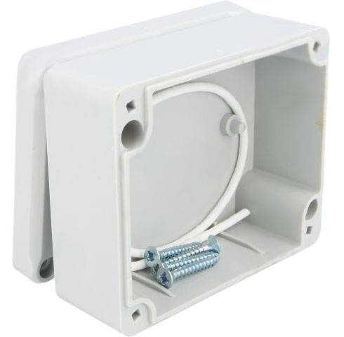
It's not tested because i didn't finish the hardware yet ,but should be pretty close from what i want ..and clean..
#include <MySensors.h>

#define CHILD_ID_LEVEL 1
#define CHILD_ID_DIRECTION 2

#define TOTAL_SENSORS 16
#define TOTAL_HEIGHT_CM 150.0  // for internal reference only, we won't send cm

// Pins for the CD74HC4067 multiplexer
const int S0 = 4;
const int S1 = 5;
const int S2 = 6;
const int S3 = 7;
const int SIG_PIN = A0;

MyMessage msgLevel(CHILD_ID_LEVEL, V_LEVEL);
MyMessage msgDirection(CHILD_ID_DIRECTION, V_STATUS);

float lastReportedPosition = -1;
float previousReading = -1;
int confirmationCounter = 0;
const int CONFIRMATION_THRESHOLD = 3;

unsigned long lastReadTime = 0;
const unsigned long readInterval = 5000; // 5 seconds (adjust as needed)

void before() {
  pinMode(S0, OUTPUT);
  pinMode(S1, OUTPUT);
  pinMode(S2, OUTPUT);
  pinMode(S3, OUTPUT);
}

void presentation() {
  sendSketchInfo("Interpolated Water Level Sensor 49E", "1.1");
  present(CHILD_ID_LEVEL, S_LEVEL);
  present(CHILD_ID_DIRECTION, S_INFO);
}

void setup() {}

void loop() {
  unsigned long now = millis();
  if (now - lastReadTime < readInterval) return;
  lastReadTime = now;

  int readings[TOTAL_SENSORS];
  for (int i = 0; i < TOTAL_SENSORS; i++) {
    selectMuxChannel(i);
    delay(5);
    readings[i] = analogRead(SIG_PIN);
  }

  // Find the pair of consecutive sensors with the highest sum of readings
  int maxSensor = -1;
  int maxValue = -1;
  for (int i = 0; i < TOTAL_SENSORS - 1; i++) {
    int sum = readings[i] + readings[i + 1];
    if (sum > maxValue) {
      maxValue = sum;
      maxSensor = i;
    }
  }

  if (maxSensor < 0) return;

  float v1 = readings[maxSensor];
  float v2 = readings[maxSensor + 1];
  float frac = (v1 + v2 == 0) ? 0 : (float)v1 / (v1 + v2);

  // Relative position [0, TOTAL_SENSORS-1], inverted (top = 100%)
  float sensorPosition = maxSensor + (1.0 - frac);

  // Calculate level as percentage [0..100%]
  float levelPercent = (1.0 - sensorPosition / (TOTAL_SENSORS - 1)) * 100.0;

  // Hysteresis with 0.5% margin
  if (abs(levelPercent - previousReading) < 0.5) {
    confirmationCounter++;
  } else {
    confirmationCounter = 1;
  }
  previousReading = levelPercent;

  if (confirmationCounter >= CONFIRMATION_THRESHOLD && abs(levelPercent - lastReportedPosition) > 0.5) {
    send(msgLevel.set(levelPercent, 1)); // send percentage with 1 decimal place

    int direction = (levelPercent < lastReportedPosition) ? 1 : 0; // 1 = rising, 0 = falling
    send(msgDirection.set(direction));

    Serial.print("Level (%): ");
    Serial.print(levelPercent, 1);
    Serial.print(" - Direction: ");
    Serial.println(direction == 1 ? "RISING" : "FALLING");

    lastReportedPosition = levelPercent;
  }
}

void selectMuxChannel(int channel) {
  digitalWrite(S0, bitRead(channel, 0));
  digitalWrite(S1, bitRead(channel, 1));
  digitalWrite(S2, bitRead(channel, 2));
  digitalWrite(S3, bitRead(channel, 3));
}
And theres more.... i asked for he..she..it.. explain me the behavior of the code and this is what it explain:
🎯 Purpose of the Code
This Arduino sketch reads analog values from 16 linear Hall effect sensors (49E) connected via a CD74HC4067 16-channel analog multiplexer to measure the position of a floating magnet (e.g., on water). It calculates the water level as a percentage (0% = bottom, 100% = top) and detects the direction of change (rising or falling water level). The data is then sent via MySensors to a gateway/controller.

🔌 Hardware Involved
16 Hall Effect Sensors (49E) arranged vertically to detect a magnet's position.

CD74HC4067 multiplexer to connect all 16 sensors to a single analog pin (A0).

MySensors library for wireless communication (e.g., with an MQTT or home automation gateway).

⚙️ Main Code Behavior
1. Initialization
before(): Configures the multiplexer select lines S0 to S3 as outputs.

presentation(): Sends node and sensor info to the MySensors controller.

setup(): Empty in this version (can be used for future initialization).

2. Main Loop (loop())
Runs every 5 seconds (readInterval = 5000 ms):

a. Read Sensor Values
Iterates through all 16 channels of the multiplexer.

For each channel, selects the sensor via selectMuxChannel(i) and reads its analog value from pin A0.

Stores all values in the readings[] array.

b. Find Position of the Magnet
Finds the pair of consecutive sensors with the highest combined reading (indicating proximity of the magnet).

Uses those two sensors to calculate a more accurate interpolated position (sensorPosition), including fractional values.

c. Convert to Water Level Percentage
Translates the sensor position to a percentage level, with 100% at the top sensor and 0% at the bottom.

Uses:

cpp
Copiar
Editar
float levelPercent = (1.0 - sensorPosition / (TOTAL_SENSORS - 1)) * 100.0;
d. Hysteresis Filtering
Uses a confirmation counter to avoid sending data for small noise fluctuations.

Only reports new data if the level has changed significantly (by more than 0.5%) and remains stable for 3 readings.

e. Send Data (if changed significantly)
Sends the level as a float with 1 decimal point.

Sends the direction:

1 for rising water level

0 for falling water level

Prints this info to the serial monitor as debug output.

🧠 Smart Features in the Code
Interpolation: Instead of picking a single sensor, it uses interpolation between the two strongest sensors to increase resolution.

Noise Filtering: Uses hysteresis and confirmation logic to avoid spamming updates due to noise.

Direction Detection: Reports whether the water is rising or falling.

📤 Output (via MySensors & Serial)
V_LEVEL message: Water level percentage (e.g., 72.5%)

V_STATUS message: Direction (1 = up/rising, 0 = down/falling)

Serial example output:

mathematica
Copiar
Editar
Level (%): 72.5 - Direction: RISING
🧪 Use Cases
Smart water tank monitoring

Sump pit level monitoring

Reservoir or hydroponics water level sensing

Any linear position tracking using a magnet + Hall sensors

Let me know if you’d like a diagram or simulation example of how this works!


