Navigation

    • Register
    • Login
    • OpenHardware.io
    • Categories
    • Recent
    • Tags
    • Popular
    1. Home
    2. Tmaster
    3. Best
    • Profile
    • Following
    • Followers
    • Topics
    • Posts
    • Best
    • Groups

    Best posts made by Tmaster

    • My Shiny Gateway and Irrigation system sHiNyBoX! :P

      Hello everybody.
      Since i discover this awesome project open source (mysensors) and the awesome work done here, i have been converted all my arduinos to Mysensor library ,because i already had Vera lite managing my home.

      so lets share what i already did. **Pictures!!!! **

      First, my gateway:
      i used a round small box , a ftdi adapter,and a 5v promini with 3.3v regulator on nrf24 .
      On picture is a normal nrf24 but then i use a amplified version that have an coaxial cable connected and an 2.4ghz antenna on outside roof(attach to my external TV antenna) ,So i can receive and send information to all my incoming sensors ,in all my garden(+3500m2) and it can receive inside home signal aswell.

      Alt text

      Alt text

      Alt text

      And then ,on 3rd day ,I created an irrigation control......

      Its not tested on vera yet, but at first look i have some work to do before it work properly. And i need replace this power wires for 12vpower adapter ones.

      Look at the switch ... you cant see it ... but its inside top rubber. just press on rubber and its water proof πŸ™‚

      Alt text

      Alt text

      Alt text

      Alt text

      Sory about my English errors ,not my natural language:P

      posted in My Project
      Tmaster
      Tmaster
    • Egg incubator IOT v3.0

      Do you think you've seen all kinds of projects here? So ..think again. πŸ™‚
      There it is my chicken eggs encubator .
      Made from a 25 liters plastic storage box and some foam outside to prevent heat loss.
      i used 2 X 18w halogen g9 bulbs and a 230v dimmer to decrease light brightness.

      There is a diagram above from fritzing. I uses an main arduino that controls a SSR relay for controls halogen light bulbs. this light bulbs are dimmed to half(in my case)
      for hold temperature much time as possible without decrease temperature.That makes SSR stay on for some minutes before goes off again. if halogen light are to powerfull makes the SSR goes on and off many times in short period. the ideal situation is having the dimmer controlled by arduino and hold temperature without turn ligh off ,but i didn't got this dimmer yet(is there any one ready for try it? πŸ˜› ).

      this is the 3rd version i build and all the other version hatch almost all eggs(+/-80%) even with some issues on controlling temperature.i only had 1 fan and that caused some zones that overheated (more on coners).
      Now i have 2x120mm(0.10A) pc fans that can spread hot air the same way in all this box.

      Then i have a secondary arduino that it's for safe features. it controls an alarm buzzer(pc speaker) ,its connected to an temperature sensor (ds18b20) and send temperature to emoncms.com through an nrf24 wireless board
      If temperatures goes over 39ΒΊC or below 30ΒΊC it sound an noisy alarm.Just in case main arduino or DHT22 fail.

      Egg roller its made os aluminium and plastic egg racks cutted and glued with hot glue(screws were better but this is enought to hold eggs).it makes 45ΒΊ each side.
      An High torque servo roll every 60 minutes. Note that an regular servo does not have enough torque should be an high toque version.

      0_1503674323666_IMG_20170825_100105.jpg
      eggs ready to start hatching! note the ds18b20 sensor in the back of the DHT22 sensor.they will stay same height than egg rack.

      0_1503674377143_IMG_20170825_095715.jpg

      0_1503674450331_IMG_20170825_095958.jpg
      2x18w halogen lighs

      0_1503674483401_IMG_20170825_100427.jpg
      lcd screen is configured for simplicity . code have hours and days passed and remaining ,but i decide use just passed days, temperature manual offset and time for next egg roll(minutes),and of course temperature and humidity on first line.

      0_1503674561645_IMG_20170825_100507.jpg

      0_1503674748968_IMG_20170825_100348.jpg

      0_1503674763845_IMG_20170825_100159.jpg
      its a mess of cables ...i know. It's what happening when we always improve our project until it be a final version πŸ˜›
      I used usb cables from computer cases for wire sensors, it work really well .
      There's 2 solid state relays on picture but we only need one.

      Parts:
      2x 12v 120mm pc fan(0.10A -slow speed/low noise)
      1x LM2596
      1x High torque servo or step motor(need additional controller).
      1x 5v Arduino pro mini (or equivalent )
      1x DHT22
      1x 5v relay Or SSR G3MB-202P Solid State
      1x 2 lines I2C 1602 LCD (i2c ,not serial) or 4 lines if you what more info on screen like time left and time spent clock.
      2x monetary switch
      2x 10k resistors
      2x 18w halogen light bulbs
      2x G9 Ceramic Sockets
      1x AC 220V 2000W SCR Voltage Regulator (overkill for 36W i know, but it cost 1.50€ on ebay)

      Optional parts
      1x 3.3v pro mini (or equivalent)
      1x computer speaker(buzzer)
      1x DS18b20
      1x NRF24L01
      1x 4.7K Resistor
      1x 3.7v litio battery (cellphone or 18650 cell)
      1x Battery Protection Board(just for charge battery before start hatching)
      note: this battery just hold main arduino in case of power failure. During normal work it never charge or discharge due 5v on line from LM2526

      FRITZING PROJECT:
      0_1504458462680_eggencubator v2.fzz

      0_1504458420052_egg encobator v2.jpg

      CODE:

      // Servo version of
      // Incubator code with lcd 16x2 ####--->>  I2C (4 wires) <<---  ###
      // ---------------------------------------------
      #include <Wire.h>
      #include <LiquidCrystal_I2C.h>
      
      #include "DHT.h"
      #include <Servo.h>
      #define DHTPIN 4                              // Define the temp sensor data pin
      #define DHTTYPE DHT22                         // define the temp/hum sensor type
      #define RELAY_1  7                              // define the relay 1 and 2 control pin
      #define RELAY_2  8
      
       
      Servo myservo;                                // create servo object to control a servo
      DHT dht(DHTPIN, DHTTYPE);                     //initialize the temp sensor
      
      LiquidCrystal_I2C lcd(0x3F,2,1,0,4,5,6,7,3, POSITIVE);    //set up what port the LCD will use
                            
      int pos = 0;                                  // variable to store the servo position
      int istate = 0;
      
      const int  buttonPin1 = 5;    // the pin that the Up pushbutton is attached to
      const int  buttonPin2 = 6;    // the pin that the Down pushbutton is attached to
      int buttonState1 = 0;
      int buttonState2 = 0;
      float val = 0; //val to increment/decrement (buttons/ threshold)
      
      int is, im, ih, id, ida, iha, ima;                      // variables for time
      float time, s1, m1, h1, d1;                   //  Set up variables to calculate time
      int ic, ip, ik;
      byte thermo[8] = {B00100, B01010, B01010, B01110, B01110, B11111, B11111, B01110}; //thermometer icon
      byte drop[8] = {B00100, B00100, B01010, B01010, B10001, B10001, B10001, B01110}; //drop icon
      byte arrow[8] = { B00100,  B01010,  B10101,  B00100, B10101,  B01010,  B00100,}; // smile icon
      byte tim[8] = {B00000, B01110, B10101, B10101, B10011, B10001, B01110,}; // clock icon
      
      int END = 0;
      unsigned long previousMillis = 0;
      const long interval = 3600000UL; //timer for roll eggs 1HOUR
      
      void setup()
      {
       Serial.begin(9600);
      
        pinMode(buttonPin1, INPUT);
        pinMode(buttonPin2, INPUT); 
        dht.begin();                                //start the temp sensor
        pinMode(RELAY_1, OUTPUT);
        pinMode(RELAY_2, OUTPUT);
        
        lcd.begin (16,2);                          // columns, rows.  use 16,2 for a 16x2 LCD, etc.
        lcd.clear();                                // start with a blank screen
        lcd.setCursor(0, 0);                        // set cursor to column 0, row 0 (the first row)
        lcd.print("Incubatora 1.0");                 // opening line
        lcd.setCursor(0, 1);                        // set cursor to column 0, row 1
        lcd.print("A iniciar!");
        delay(2000);
                                
        lcd.createChar(0, thermo);
        lcd.createChar(1, drop);
        lcd.createChar(2, arrow);
        lcd.createChar(3, tim);
        myservo.attach(9); // servo control is set to pin 9 (usually yellow wire is control, black goes to ground red goes to +5V)
        myservo.write(70); //put the servo at intitial position of 16 degrees
        myservo.detach();
      }
      
      //loop to read the sensor and display
      void loop() {
      
        int buttonState1 = digitalRead(buttonPin1);
        int buttonState2 = digitalRead(buttonPin2);
        delay(10);
      
      if (buttonState1 == HIGH)
           {     
           val-=0.1;
          } 
         else if (buttonState2 == HIGH) 
         { 
          val+=0.1;
         }


        float h = dht.readHumidity();                 // Read the humidity
        float t = dht.readTemperature();              // Read temperature in celsius
        float f = dht.readTemperature(true);          // get the temperature in Fahreheit
        
         //Temperature controller
          if (t >= (37.7 + val))
          {                       //  Set the temperature for the relay to come on (ideal 37.7ΒΊC)     
            digitalWrite(RELAY_1,LOW);          // TO HOT: Turns Relay OFF
          digitalWrite(RELAY_2,LOW);
          }
      
           if (t <= (37.5 + val))
         {                       //  Set the temperature for the relay to come on (ideal 37.7ΒΊC)    
            digitalWrite(RELAY_1,HIGH);          // TO HOT: Turns Relay ON
          digitalWrite(RELAY_2,HIGH);
          }
        
        
        // uncomment to compute heat index in Fahrenheit (the default)
        //float hif = dht.computeHeatIndex(f, h);
        // Compute heat index in Celsius (isFahreheit = false)
        //float hic = dht.computeHeatIndex(t, h, false);
        time = millis();                            //  Get time in milliseconds since tunit turn on
        s1 = time / 1000;                           //  Convert time to seconds, minutes, hours, days
        m1 = s1 / 60;
        h1 = m1 / 60;
        d1 = h1 / 24;
        id = int(d1);  //d                             //  Strip out remainder to leave Days:Hours:Minutes:Seconds
        ih = int((d1 - int(d1)) * 24); //h
        im = int((h1 - int(h1)) * 60); //m
        is = int((m1 - int(m1)) * 60);  //s


        // Calculate approximate TIME till hatch (assume 21 days to hatch)   -      not used yet
        ida = 21 - id;
        iha = 24 - ih;   
        ima = 60 - im;


        if (isnan(h) || isnan(t) || isnan(f)) {
          // if sensor can't be read
          lcd.clear();
          lcd.setCursor(0, 0);
          lcd.print("Falha No Sensor");
          Serial.print("Falha No Sensor" );
           digitalWrite(RELAY_1,HIGH);          // ERRO: Turns 1 Relay OFF to not kill all the eggs
          digitalWrite(RELAY_2,LOW);
          delay(5000);
          return;
        }
        else {      //  for  LCD 16x2
          //sensor was read succesfully so print values to LCD 16x2
          lcd.clear();                                // Clear the LCD
          //Print temperature and humidity in first two lines
          lcd.setCursor(0, 0);
          // lcd.print("Temperature:");
      
          lcd.write(byte(0));                       // Write the Thermometer icon
           lcd.print(t , 1);
          lcd.print((char)223);
          lcd.print("C  ");
          
          //lcd.setCursor(0,1);
          lcd.write(byte(1));                         // Write the drop icon
          // lcd.print("Humidade:");
           lcd.print(h, 0);
           lcd.print("%");
        //   lcd.print(" ");
        //  lcd.print(ic);
          lcd.setCursor(0, 1);
          
          //lcd.print("  ");
          lcd.write(byte(3));
          lcd.print(" ");
          // Print timein format Time: xxd:xxh:xxm:xxs
        lcd.print(id);
          lcd.print("d ");
         /* lcd.print(ih);
          lcd.print(":");
          lcd.print(im);
          lcd.print(" "); 
          lcd.print(is); lcd.print(" ");*/
          lcd.print(val,1);    
      
      
        if (21 - id <= 3){
             // Print days left till hatch
             lcd.print("!");
           END = 1; //stop move eggs
         }
        
         // this section is to roll the eggs   
      unsigned long currentMillis = millis();
      
       int tleft = ((currentMillis - previousMillis)/ 1000) /60;
      lcd.print(" ");  lcd.write(byte(2));  
       lcd.print(tleft); 
      
       
      if (currentMillis - previousMillis >= interval)
      {
        previousMillis = currentMillis;
       
      if(istate == 0 && END == 0){  
        //myservo.attach(9);
         for (pos = 80; pos <= 155; pos += 1) { // goes from 16 degrees to 80 degrees  in steps of 1 degree
           myservo.attach(9);
           myservo.write(pos);
           istate=1;
           delay(50);
         }
         myservo.detach();
       }
      else if( istate == 1 && END == 0)
      { 
       // myservo.attach(9);        
         for (pos = 155 ; pos >=80; pos -= 1) { // goes from 80 degrees to 0 degrees
          myservo.attach(9);
           myservo.write(pos); 
           istate = 0;
           delay(50);                      // slow the servo down a bit to turn the eggs        
         }
         myservo.detach();
       }
      
      }
        
             // Pause for 2 seconds
         delay(2000);
        }
      }


      auxiliary/optional arduino

      #define MY_DEBUG


      // ---------------------------------------------
      #define MY_RADIO_NRF24
      
      
      #include <SPI.h>
      #include <MySensors.h>  
      #include <OneWire.h>
      #include <DallasTemperature.h>
      
      
      #define MY_RF24_PA_LEVEL RF24_PA_LOW
      
      // Data wire is plugged into pin 2 on the Arduino
      #define ONE_WIRE_BUS 2
       #define CHILD_ID_EGG 12 //id
      // Setup a oneWire instance to communicate with any OneWire devices 
      // (not just Maxim/Dallas temperature ICs)
      OneWire oneWire(ONE_WIRE_BUS);
       
      // Pass our oneWire reference to Dallas Temperature.
      DallasTemperature sensors(&oneWire);
      const int buzzer = 3; //buzzer to arduino pin 3
      unsigned int al = 0;
      
      bool receivedConfig = false;
      bool metric = true;
      MyMessage msg(CHILD_ID_EGG,V_TEMP);
      
      
      unsigned long previousMillis = 0;        // will store last time sent temperature
      const long interval =900000; //15min
      
      void before()
      {
        // Startup up the OneWire library
        sensors.begin();
      }
      
      void setup()
      {
        
            sensors.begin();
             pinMode(buzzer, OUTPUT); // Set buzzer - pin 9 as an output
      }
      
      
      void presentation() {
        // Send the sketch version information to the gateway and Controller
        sendSketchInfo("Temperature eggs", "2.0");
      
       
        // Present all sensors to controller
             present(CHILD_ID_EGG, S_TEMP);
        }


      void loop() {
      
        sensors.requestTemperatures(); // Send the command to get temperatures
      
      
        //Serial.print("Temperature is: ");
      
          float t =sensors.getTempCByIndex(0); 
      
      //Serial.print(t); 
      //-----------------------------timer & send-------------------------------------
       unsigned long currentMillis = millis();
      
        if (currentMillis - previousMillis >= interval) {
             
              previousMillis = currentMillis;
             
      // Send in the new temperature every 5min send(msg.setSensor(t).set(t,1));  
      send(msg.set(t,1));  Serial.print(t); 
        }
      //---------------------------------------------------------------------------------------
      
      //alarm buzzer-------
       if (t >=37.0) {    //(37ΒΊc)
        al=1;                 //save 1 when 1st temperature estabilize. after that "al" will be always 1 until reset/shutdows . This makes the alarm not start when incubator still cold on warm up
         }                      
      
         //Temperature controller alarm
          if (t >= 39.0) {  
            for (unsigned int i=750; i<2500; i++) {  // TO HOT: alarm!
            tone(buzzer, i ,700);
              delayMicroseconds (15);
            }
      delay(2000);
          }
      
              
        if (t <= 30.0 && al == 1) {                       
       
            for (unsigned int i=750; i<2500; i++) {  // TO HOT: alarm!
            tone(buzzer, i ,700);
              delayMicroseconds (15);
            }
      delay(2000);
          }


        }


      NOTE: English it's not my language. i'm sorry some errors that can happens πŸ˜›

      posted in My Project
      Tmaster
      Tmaster
    • Domoticz with DIY "razberry" card

      hello. like o wrote before my veralite dies after 4 years of work.
      So now i'm on Domoticz.For the dead vera lite i recover the z-wave part. i had some doubts that it works but i have seen n razberry cards that the hardware its the same,so why not try.
      I just cutted the 4 layers pcb and solder 4 wires on zm3102 chip directly(tx,rc,vcc and gnd). some hot glue and some nail polish /or epoxy to seal cutted sides.There are no working leds but how cares. and yea.I have an external antena πŸ™‚ . Everything fits inside vera case aswell(recycling on the best),raspbery,zwave card and mysensors GW.
      in beginning domoticz didn't detect it like in official zwave cards ,there are some procedures to make before,but soon as setup button gets blue ,was just reset or exclude and then include nodes again on Domoticz. until now (24hours later) everything still work like a charm ,And let me say Domoticz is far more complete than mios os.

      3_1520793722430_IMG_20180310_183236_962.jpg 2_1520793722429_IMG_20180310_183202_675.jpg 1_1520793722429_IMG_20180310_183135_708.jpg 0_1520793722429_IMG_20180310_181022_554.jpg

      posted in Domoticz
      Tmaster
      Tmaster
    • CHATGPT My new best friend!

      Hello guys.
      Years after MySensors release , and we still here talking here about, on on my electronic engineer opinion ,the best/usefull open source library ever!!! i say that because all my outdoor appliances, work with this stable library . Water heating solar panels, irrigation systems , outdoor light , main gate and basement gate can report status and command, water level from the irrigation system etc etc. Even for save water because i have timeouts and safe features for not water water or forget plants watering.... i only don't use the inside because my hardware don't fit inside concrete wall boxes....
      Now since i had to debug one of my sensors and realize the power of chatgpt now i just got lazy and don't program my sensors myself. I just explain what i want and the AI do it.
      have you tried it? Amazing .
      This morning i did a water level sensor to replace my sonar one. Asked one mysensors code for 16 hall effect sensors connected to a mux cd74hc4067 and it suggest ; why no use interpolation,why not use sensor
      hysteresis? hyster... what? i didn't its called like that. want cms or percentage....- DO it!! . 10 minutes later i had a hell of compacted code that do what i want WITHOUT BUGS and compile errors!!! yes,it's amazing because i'm not programmer and i can program c++ on arduino code but not much more than this....
      So don't stop your creativity because you are not very good programmer and you don't even know how to start you project. mysensors library it's well known from AI . .thank you my sensors team πŸ‘ πŸ’ͺ

      posted in General Discussion
      Tmaster
      Tmaster
    • RE: Timer (Emergencie)

      if it is an emergency button should be connected directly to relay (connected by hardware). And not using code,because if arduino it's freezed it will not respond and you cant stop it

      posted in My Project
      Tmaster
      Tmaster
    • RE: #define DEFAULT_RFM69_IRQ_PIN

      @zboblamont said in #define DEFAULT_RFM69_IRQ_PIN:

      So long as these are set before including the MySensors library it should indeed override the defaults.

      OMG. this is the problem! i was defining AFTER Including Mysensors library. well i should knew that if i know more about programingπŸ˜– 🀦

      this code now is working comunicating well.

      I still having an issue. termometer doesn't appear on domoticz. i think it's well presented... i'm not sure whats happen. but the axel for angle, that i need is , working good already .

      The corret statement is .
      #define MY_RFM69_IRQ_PIN 3
      #define MY_RFM69_IRQ_NUM 1

      /*
       ->  __  __       ____
       -> |  \/  |_   _/ ___|  ___ _ __  ___  ___  _ __ ___
       -> | |\/| | | | \___ \ / _ \ `_ \/ __|/ _ \| `__/ __|
       -> | |  | | |_| |___| |  __/ | | \__ \  _  | |  \__ \
       -> |_|  |_|\__, |____/ \___|_| |_|___/\___/|_|  |___/
       ->         |___/                      2.3.2
      */
      
      #define MY_DEBUG
      #include <basicMPU6050.h> 
      #define MY_RADIO_RFM69
      #define MY_RFM69_IRQ_PIN 3 //!< DEFAULT_RFM69_IRQ_PIN
      #define MY_RFM69_IRQ_NUM 1
      #include <MySensors.h>
      #include <RunningMedian.h>
      RunningMedian samples = RunningMedian(100);
      
      #define CHILD_ID 98
      #define CHILD_ID_TEMP 99


      MyMessage msg(CHILD_ID, V_LEVEL);
      MyMessage msg1(CHILD_ID_TEMP,V_TEMP);
      // Create instance
      basicMPU6050<> imu; //credits:https://github.com/RCmags/basicMPU6050
       float incl;
       
        static uint8_t sentValue;
      void presentation()
      {
        // Send the sketch version information to the gateway and controller
        sendSketchInfo("TANQUE", "2.3");
      
        // Register all sensors to gw (they will be created as child devices)
          present(CHILD_ID, S_MOISTURE);
           present(CHILD_ID_TEMP,S_TEMP);
      }
      
       
      void setup() {
        // Set registers - Always required
        imu.setup();
      
        // Initial calibration of gyro
        imu.setBias();
      
        
      }
      
      void loop() { 
        // Update gyro calibration 
         imu.updateBias();
        
         incl= imu.ay();
      
         int val = ((incl+1)*50);
      
         int x = val;
        
        samples.add(x); 
       
       //long m = samples.getAverage(); 
        int m = samples.getMedian();
        delay (200);
      
              
        if (m != sentValue)
         {
         
       
         send(msg.set(m));
         float temp = imu.temp();
        send(msg1.set(temp,1));
        sentValue = m;
        delay (5000);
        
         }
      }   
      
      
      posted in General Discussion
      Tmaster
      Tmaster
    • RE: Egg incubator IOT v3.0

      And that is the result . 14 chicks of 25eggs ,but i could say that was 100% sucess because the other eggs were not fertilized. not even a single dead before or after hatch. Its not the arduino the most versatile machine? πŸ™‚

      0_1505665439485_IMG_20170914_145207.jpg

      top left chic just born 10min before i take the picture:P
      0_1505665502812_IMG_20170914_145158.jpg

      posted in My Project
      Tmaster
      Tmaster
    • RE: Will a NRF24L01+PA+LNA help with my signal problems

      Hi to @Greymarvel .Well i already seen this movie before. I bought diferent nrf24 nodes,amplifed ,not amplified,with or without capacitors. In fact i had worst redults with amp nodes. I just change to rfm69hw and w
      . No more low power/high power...etc. now i got my 4000m2 terrain covered (around 80m long).
      I didn't check max range but i never had lost a packet again. I was a very good increment on my network stability.
      That fake nrf24 chips are crazy and unstable and yes,all ebay cheap nodes are fake second i know.

      posted in Development
      Tmaster
      Tmaster
    • RE: Roller shutter(s_cover) on Domoticz

      thank you for reply @mfalkvidd
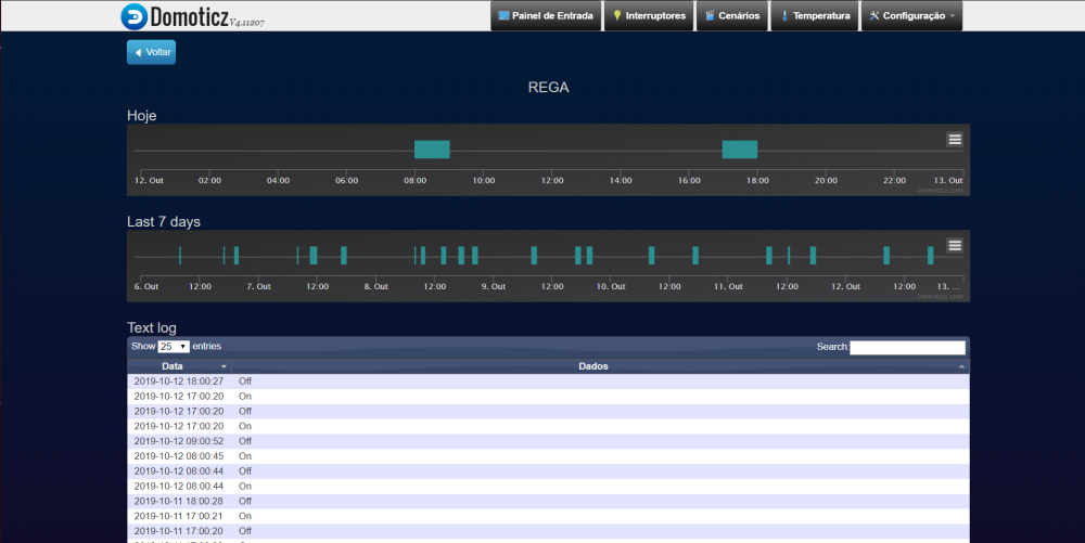
      Payload like 100 shoud be 100% on domoticz, right? how does domoticz "know" that a blindcover /or shutter is open or close? because it's not respondig to that...

       
       __  __       ____
      |  \/  |_   _/ ___|  ___ _ __  ___  ___  _ __ ___
      | |\/| | | | \___ \ / _ \ `_ \/ __|/ _ \| `__/ __|
      | |  | | |_| |___| |  __/ | | \__ \  _  | |  \__ \
      |_|  |_|\__, |____/ \___|_| |_|___/\___/|_|  |___/
              |___/                      2.3.1
      
      16 MCO:BGN:INIT NODE,CP=RRNNA---,REL=255,VER=2.3.1
      26 MCO:BGN:BFR
      28 TSM:INIT
      30 TSF:WUR:MS=0
      34 TSM:INIT:TSP OK
      34 TSF:SID:OK,ID=4
      36 TSM:FPAR
      1257 TSF:MSG:SEND,4-4-255-255,s=255,c=3,t=7,pt=0,l=0,sg=0,ft=0,st=OK:
      1423 TSF:MSG:READ,0-0-4,s=255,c=3,t=8,pt=1,l=1,sg=0:0
      1429 TSF:MSG:FPAR OK,ID=0,D=1
      3264 TSM:FPAR:OK
      3264 TSM:ID
      3266 TSM:ID:OK
      3268 TSM:UPL
      3276 TSF:MSG:SEND,4-4-0-0,s=255,c=3,t=24,pt=1,l=1,sg=0,ft=0,st=OK:1
      3315 TSF:MSG:READ,0-0-4,s=255,c=3,t=25,pt=1,l=1,sg=0:1
      3321 TSF:MSG:PONG RECV,HP=1
      3325 TSM:UPL:OK
      3328 TSM:READY:ID=4,PAR=0,DIS=1
      3540 TSF:MSG:SEND,4-4-0-0,s=255,c=3,t=15,pt=6,l=2,sg=0,ft=0,st=OK:0100
      3567 TSF:MSG:READ,0-0-4,s=255,c=3,t=15,pt=6,l=2,sg=0:0100
      3786 TSF:MSG:SEND,4-4-0-0,s=255,c=0,t=17,pt=0,l=5,sg=0,ft=0,st=OK:2.3.1
      4005 TSF:MSG:SEND,4-4-0-0,s=255,c=3,t=6,pt=1,l=1,sg=0,ft=0,st=OK:0
      4046 TSF:MSG:READ,0-0-4,s=255,c=3,t=6,pt=0,l=1,sg=0:M
      4263 TSF:MSG:SEND,4-4-0-0,s=255,c=3,t=11,pt=0,l=5,sg=0,ft=0,st=OK:Cover
      4483 TSF:MSG:SEND,4-4-0-0,s=255,c=3,t=12,pt=0,l=3,sg=0,ft=0,st=OK:2.0
      4708 TSF:MSG:SEND,4-4-0-0,s=0,c=0,t=5,pt=0,l=22,sg=0,ft=0,st=OK:shuttle for Livingroom
      4716 MCO:REG:REQ
      4929 TSF:MSG:SEND,4-4-0-0,s=255,c=3,t=26,pt=1,l=1,sg=0,ft=0,st=OK:2
      4956 TSF:MSG:READ,0-0-4,s=255,c=3,t=27,pt=1,l=1,sg=0:1
      4962 MCO:PIM:NODE REG=1
      4964 MCO:BGN:STP
      getting rolltime from eeprom: 
      28.00
      getting state from eeprom: 
      0
      4968 MCO:BGN:INIT OK,TSP=1
      Sending initial value
      5185 TSF:MSG:SEND,4-4-0-0,s=0,c=1,t=29,pt=1,l=1,sg=0,ft=0,st=OK:0
      5402 TSF:MSG:SEND,4-4-0-0,s=0,c=1,t=30,pt=1,l=1,sg=0,ft=0,st=OK:0
      5619 TSF:MSG:SEND,4-4-0-0,s=0,c=1,t=31,pt=1,l=1,sg=0,ft=0,st=OK:1
      5838 TSF:MSG:SEND,4-4-0-0,s=0,c=1,t=3,pt=2,l=2,sg=0,ft=0,st=OK:0
      

      .
      .
      .
      .
      after I give an order of CLOSE (DOWN) shutter (v_percentage=0)

      ------------     *(HERE WAS AT 100% AND I ORDER TO GO 0%(CLOSED)* -------------------
      
      exiting incoming message
      Shutters going down
      612509 TSF:MSG:SEND,4-4-0-0,s=0,c=1,t=29,pt=1,l=1,sg=0,ft=0,st=OK:0
      612728 TSF:MSG:SEND,4-4-0-0,s=0,c=1,t=30,pt=1,l=1,sg=0,ft=0,st=OK:1
      612947 TSF:MSG:SEND,4-4-0-0,s=0,c=1,t=31,pt=1,l=1,sg=0,ft=0,st=OK:0
      613167 TSF:MSG:SEND,4-4-0-0,s=0,c=1,t=3,pt=2,l=2,sg=0,ft=0,st=OK:100
      99
      98


      (...)
      
      7
      6
      5
      4
      3
      2
      1
      0
      Shutters halted X
      saving state to: 
      0
      645519 TSF:MSG:SEND,4-4-0-0,s=0,c=1,t=29,pt=1,l=1,sg=0,ft=0,st=OK:0
      645738 TSF:MSG:SEND,4-4-0-0,s=0,c=1,t=30,pt=1,l=1,sg=0,ft=0,st=OK:0
      645957 TSF:MSG:SEND,4-4-0-0,s=0,c=1,t=31,pt=1,l=1,sg=0,ft=0,st=OK:1
      646176 TSF:MSG:SEND,4-4-0-0,s=0,c=1,t=3,pt=2,l=2,sg=0,ft=0,st=OK:0
      
      ------------    *(HERE REACH 0%)* -------------------
      
      posted in Domoticz
      Tmaster
      Tmaster
    • RE: bluetooth instead of wifi

      because wifi is not the most safe for humans... sleeping etc

      what are you talking about???
      are you the ones that say wifi boils water on a cup?

      mysensors library works on nrf24l01+ modules, Not wifi. its a kind of Bluetooth already... anyway Bluetooth is 2.4ghz like wi-fi, but Bluetooth consumes less power (Theoricly)

      posted in My Project
      Tmaster
      Tmaster
    • RE: NRF24 Range

      i'm bilding this right now: http://www.qsl.net/eb4eqa/bt_yagi/bt_yagi.htm
      i tell you what is the increment of range in the next weekend ...

      0_1494431994498_upload-5f249d36-0af2-4bd6-b4f3-0b4b13788dad

      i have one of temp sensors under a water solar panel and the aluminium from the frame get me crazy because that sensor lose many of the sent reads to gw. i will finish that yagi antenna and solder that to my nrf24 and i hope signal increase performance.

      in my house (i dont have neighboard les than 80m with wifi signal and noise from other routers or any king of 2.4ghz signals ) i can send a door sensor signal(from my entrance gate) by 50m and 1 wall . that one have this antena alredy on tx:
      http://martybugs.net/wireless/collinear.cgi
      0_1494432012836_upload-41e2f334-6ce8-4308-8b9c-e67b2af5c252

      posted in General Discussion
      Tmaster
      Tmaster
    • RE: 3.3 or 5v tranformer for mysensors projects

      hi guys . I just discovered how some main zwave brands power their modules.
      the chip used its LNK302DN and the sckematic its(adapted for 5v or 3.3v):

      0_1496351141857_sckematic.jpg

      SEE PAGE 4 AND 5
      http://www.farnell.com/datasheets/2059771.pdf?_ga=2.242203521.2016163251.1496347222-1734612754.1489089187

      That's something!πŸ’£

      posted in Hardware
      Tmaster
      Tmaster
    • RE: Hacking a remote control Hunter ceiling fan controller

      what about buid an dimmer sensor ,put it directly to the fan motor and forget that remote? that is what i would do. that its all about create a scene for that fan, temperature limits,motion .... smat fan you know πŸ™‚

      what is the motor power ?

      posted in My Project
      Tmaster
      Tmaster
    • RE: Crazy timer on my sketch

      @mfalkvidd said in Crazy timer on my sketch:

      the debug log will probably give good insight to why the node reacts early.

      i just discovered the auto-formatting right now πŸ™‚

      About debug (mydebug) just reacts as normal,everything as should, but in shorter time... less 70-80% of the time most the times. Tomorrow i will get the arduino that its watering right know and change the code a bit..try some "while" instead of "if" or hammering it πŸ˜‰

      posted in General Discussion
      Tmaster
      Tmaster
    • RE: hlk-pm01 are to noisy for rfm69?

      Maybe you are right and it's the proximity to a switching tranformer like this hlk-pm01 .They are all on same protoboard aprox 50x60mm. i could build a sheld on it but....now its working with the rfm69version W ok for a few days.
      The strange part is this combo was very used a few years now on made pcbs the on forum wher they had the maker/developer contest and never seen a line of this problem...

      posted in Hardware
      Tmaster
      Tmaster
    • Simple irrigation controller

      Description
      This project born from a necessity of water my domestic vegetable garden. Lettuces needs water all day and many times I forgot or don’t have time. There are other projects for irrigation but I have special requirements, it’s just one valve and valves that are sold in my country are AC24V for commercial controllers.
      So I build a controller to add to my existing Mysensors/Domoticz network that can handle an AC24V with 12V to 3V volt DC . +/-3 Volts it’s how power this AC24V volts solenoids because AC24V transformers are difficult to find and expensive for what they are(ferromagnetic). And once solenoids(coils) warms up a lot especially with DC,with 3 volt they run cold and its the minimum that my valve requires to stay open.

      How it works?
      Watering can be set on Arduino, 2 times per day ,morning and at evening. Or even once per day.
      Or can be added timers on gateway (my case Domoticz) and everything stays remotely. Personally I prefer have it hard coded on Arduino in case of transmission fail.
      I add a switch (one per valve) to turn it on every time I want and it automatically shuts down on timer that it’s set on code ,in β€œVALVE_TIME”. 1 hour by default.
      So there this timeout work in any of the timers(switch,gateway or internal timer).

      On code ,I set to β€œ225”(100% or DC12v) on mosfet (IRLZ44N) during 400ms to kick the solenoid to open and then is set to β€œ90” the rest of time to have around 3V on valve terminals. The entire project it’s powered with a standard electronic DC12V/2A transformer that powers the Arduino and the water valve.

      There are 2 leds. One "Valve Power On" and other is TX/RX,note that blink time was slowed down for better understand when is communicating or its just retrying in loop and can't reach the gateway (for example). I have really good result with RFM69H(868mhz) communications. My garden its 40m/50m of my house or GW an never realize that were lost communications.

      What I used:
      Arduino (any 328P), I used pro mini 3.3v because the RFM69
      RFM69H
      LM2596 Voltage step down 12v→3.3V (or equivalent)
      IRLZ44N or any logic level mosfet that work on 3.3V(one per valve that you use)
      x2 leds
      x2 screw terminal (2 wires)
      Push Switch (Normally open)
      Resistors x2 - 10K and x2 – 220ohm
      Protoboard (that green ones from ebay are awesome)
      wire…

      Some thoughts : On my prototypes, I rarely make a dedicated pcb, I use thin ,wire to bridge components on protoboards. They are easy to build and easy to repair or remake in case of some issue. Never had an unexpected shot-circuit. And when my board are outdoor ,I use nail polish or transparent spray paint to cover the entire board. that makes an water prof board. And believe me even ip67 outdoor cases sometimes let water get in.
      This is an example of wiring , of course in this our project we have many less wires :example

      Schematic
      0_1570911079939_f35f0b64-983b-4015-8fcd-81dc770eacf2-image.png

      Note: each extra valve(Zone) needs an extra led, switch and mosfet.

      Don’t let your garden dry! πŸ™‚

      Code

      // Set blinking period (in milliseconds)
      #define MY_DEFAULT_LED_BLINK_PERIOD 500
      #define MY_WITH_LEDS_BLINKING_INVERSE
      //#define MY_DEFAULT_ERR_LED_PIN 17
      #define MY_DEFAULT_TX_LED_PIN 17
      #define MY_DEFAULT_RX_LED_PIN 17
      
      //#define MY_DEBUG
      #define MY_RADIO_RFM69
      //#define MY_REPEATER_FEATURE
      
      #include <TimeLib.h>
      #include <SPI.h>
      #include <OneWire.h>
      #include <DallasTemperature.h>
      #include <MySensors.h>
      
      
      #define ONE_WIRE_BUS 6
      OneWire oneWire(ONE_WIRE_BUS);
      DallasTemperature sensors(&oneWire);
      //#define CHILD_ID_MOISTURE 4
      #define CHILD_ID_TEMP 21
      #define CHILD_ID_VALV1 10
      //#define CHILD_ID_VALV2 11
      
      
      #define RELAY_PIN  3  // Arduino Digital I/O pin number for relay  VALV 1 
      #define RELAY_PIN2  5  // Arduino Digital I/O pin number for relay VALV 2
      #define BUTTON_PIN  4  // Arduino Digital I/O pin number for button 
      #define LEDR1   16  // LED A2 pin
      #define LEDR2  15// LED A1 pin
      //#define LEDERRO 17  // LED A3  pin


      #define VALVE_TIME 3600000UL    //selenoid 1 goes off after () time  (7200000UL)-2HOUR
      #define readtime 1800000UL  //time between read TEMPERATURE (3600000UL) - 1HOUR
      
      //xxxxxxxxxxxxxxxxxxxxxxxxxxxxx |SET TIME HERE|     - valve1-  xxxxxxxxxxxxxxxxxxxxxxxx |
      //TIME1
      const int H1 = 17; //HOURS START PROGRAM     //time to start  selenoid1                 |
      const int M1 = 00; //MINUTES START PROGRAM                                              |
      //TIME2
      const int H2 = 8; //HOURS START PROGRAM     //time to start  selenoid1                 |
      const int M2 = 00; //MINUTES START PROGRAM
      //----------------------------------------valve2--------------------------------------- |
      
      unsigned long startMillis = 0;
      unsigned long startMillisA = 0;
      
      int reading;// the current reading from the input pin
      bool RH = false;
      int previous = LOW;
      int timer = false;
      bool timeReceived = false;
      unsigned long  lastRequest = 0;
      
      MyMessage msg1(CHILD_ID_TEMP, V_TEMP);
      MyMessage msg2(CHILD_ID_VALV1, V_LIGHT);
      
      bool state;
      
      
      void before()
      {
        // Startup up the OneWire library
        sensors.begin();  //DS18B20 LIBRARY START
      }
      
      void setup()
      {
        //request time from gw
        requestTime(receiveTime);
      
        // Setup the button
        pinMode(BUTTON_PIN, INPUT);
        pinMode(RELAY_PIN, OUTPUT);
        pinMode(RELAY_PIN2, OUTPUT);
      
        pinMode(LEDR1, OUTPUT);
        pinMode(LEDR2, OUTPUT);
        sensors.begin();  //DS18B20 LIBRARY START
      
      
        // Make sure relays are off when starting up
        digitalWrite(RELAY_PIN, LOW);
      
      }


      void presentation()
      {
        sendSketchInfo("irrigation_temp_soilMoisture", "2.0");
        present(CHILD_ID_TEMP, S_TEMP);
        present(CHILD_ID_VALV1, S_LIGHT);
      }
      void receiveTime(unsigned long time)
      {
        // Ok, set incoming time
        setTime(time);
        timeReceived = true;
      
        Serial.print("Time now is: ");
      
        Serial.print(hour());
        Serial.print(":");
        Serial.print(minute());
        Serial.print(":");
        Serial.print(second());
      }
      //#################################################################################################
      void VALV1_ON()
      {
        analogWrite(RELAY_PIN, 255);
        delay(400);
        analogWrite(RELAY_PIN, 90);
        digitalWrite(LEDR1, HIGH);
        send(msg2.set(true), false);
      
      }
      
      void VALV1_OFF()
      {
        analogWrite(RELAY_PIN, LOW);
        digitalWrite(LEDR1, LOW);
        send(msg2.set(false), false);
      }
      //#########################################################################################################3
      // βœ“ ORDER RECEIVED FROM GW  # 
      
      void receive(const MyMessage &message) {
        // We only expect one type of message from controller. But we better check anyway.
        if (message.isAck()) {
          // Serial.println("This is an ack from gateway");
        }
      
        if (message.type == V_LIGHT) {
          // Change relay state
          state = message.getBool();
      
          if (state == 1)
          {
            VALV1_ON();
          }
      
          else if (state == 0)
          {
            VALV1_OFF();
          }
      
        }
      }
      void loop()                 //loop   
      {
      
      
        unsigned long nows = millis();
        // If no time has been received yet, request it every 10 second from controller
        // When time has been received, request update every 12h
        if ((!timeReceived && (nows - lastRequest) > (10UL * 1000UL))
            || (timeReceived && (nows - lastRequest) > (43200000UL)))
        {
          // Request time from controller.
          //   Serial.println("requesting time");
          requestTime(receiveTime);
          lastRequest = nows;
        }
      
        
        //toogle  switch----------selenoid 1-------------------------------
      
        reading = digitalRead(BUTTON_PIN);
      
      
        if (reading == HIGH && RH == false)
        {
          VALV1_ON();
          RH = true;
          timer = true;
          delay(400);
        }
        else if (reading == HIGH && RH == true)
        {
          VALV1_OFF();
          RH = false;
          timer = false;
          delay(400);
        }
      
        // βœ“ time out 
        unsigned long nowMillis = millis();
      
        if ((timer == true) && (nowMillis - startMillis >= VALVE_TIME))
        {
          startMillis =  nowMillis ;
          VALV1_OFF();
          timer = false;
      
        }
      
        //βœ“ ON by time 
        if ((hour() == H1 && minute() == M1) || (hour() == H2 && minute() == M2)  )
        {
          VALV1_ON();
          timer = true;
        }


        //βœ“ time to send temperature ? 
        float temperature = sensors.getTempCByIndex(0);
      
        unsigned long nowMillisA = millis();
        if (nowMillisA - startMillisA >= readtime)
        {
          //βœ“ read temperature  sensors 
          sensors.requestTemperatures();
          send(msg1.set(temperature, 1)); //send  temp to gw
          startMillisA =  nowMillisA ;  //reset time
        }
      }
      

      Todays Domoticz log from this sensors:

      0_1570911754580_26158c40-f747-4cb4-8a58-c89f2a97cd17-image.png

      posted in My Project
      Tmaster
      Tmaster
    • RE: timealerts and mysensors library conflict?

      pretty difficult question hum? lol

      i solve it by forgetting TimeAlarms.h and set just an hour that triggers the solenoid like this
      (HX and MH its the time,[hours] and [minutes] defined at beginning and its set manually)

       if (hour() == HX && minute() == MX )
          {
           analogWrite(RELAY_PIN,255);    
           delay(400);
          analogWrite(RELAY_PIN,90);  //half voltage(+-5v to 6v) to not burn valve selenoid(hold voltage) 
            digitalWrite(LEDR1,HIGH);
            //Serial.print("time up");
         
          }
          else if  (hour() == HXend && minute() == MXend ) 
          {
         digitalWrite(RELAY_PIN,LOW);
         digitalWrite(LEDR1,LOW);
         //Serial.print("time down");
          }
      
      
      posted in Troubleshooting
      Tmaster
      Tmaster
    • RE: Crazy timer on my sketch

      Nice catch! i didnΒ΄t see that . thank you

      posted in General Discussion
      Tmaster
      Tmaster
    • RE: Irrigation controller

      Erik .if you dont have a gateway or mysensors implemented in your house yet,you should do someting simple.that schetch its crazy for a new start person.
      Some relays that fire by time its enouf. Wifi part that you want provably its realy Wi-Fi,not mysensors conection that its an wireless protocol,(not wifi). We are deep in summer,its not time to make a new irrigation controller from 0 and tryitπŸ˜‹

      posted in Troubleshooting
      Tmaster
      Tmaster
    • RE: Crazy timer on my sketch

      @mfalkvidd that was the problem! I correct the code and timers are working perfect now. I will post the skematic and code this night on projects for if someone want to use it . Very handy on summer for water some vegetables like i do. It's a very simple build.

      posted in General Discussion
      Tmaster
      Tmaster
    • RE: WI-FI IOT modules

      I think i touch the rigth spot! WIFI ☺ ☺ ~
      but my initial post was more about if they are reliable than if they are safe...
      even a wood door it's not safe...an kick and you are in ... i don't believe someone will start robbing my house ,by entering in the shutter iot module by an wifi hack and open the shutter,brake doble glass windows and enter....
      It's more a question if they are pratical and reliable? tey cost less than half of an zwave module..big point here...
      and my main concern is ,are they all day comunicating with router or they usualy sleep? i'm not sure how wi-fi devices like esp8266 work. If they ping the router regularly or what?

      posted in General Discussion
      Tmaster
      Tmaster
    • RE: Raspberry PI killing memory cards

      my Domoticz its running on a PNY SD card for more than 2 years and didn't die yet. But i almost don't have power cuts . Any case i have another sandisk ultra sd with an clone from the running SD ready to replace this in case of fail.
      You can buy and replace an raspberry by an fast and more expensive device...but this sd cards cost 3.75€ !!! power consumption of 1.5w- 1.9w in idle... what else can i want from my domotic system! πŸ™‚

      edit: i have 4 or 5 sensors transmitting and writing every 15min, so sd write, it's not too heavy,standart usage.

      posted in General Discussion
      Tmaster
      Tmaster
    • RE: Moisture penetrates my outdoor enclosures...

      i use the simplest boxes that you find,that suface mount with 4 screws and ruber on door.
      But be carefull with wall mount screws. if you drill the back of the box ,water come in beind this box. so this ones,the scrfew holes are outside the encosure an box is sealed...
      another tip is drill on bottom for pass cables but put some neutral silicone. hot glue let water come in with time because expansion coeficient is diferent that the plastic box and open gaps

      4c9e3f72-078c-46a9-9750-e0f495712c7c-image.png

      posted in General Discussion
      Tmaster
      Tmaster
    • RE: #define DEFAULT_RFM69_IRQ_PIN

      @zboblamont said in #define DEFAULT_RFM69_IRQ_PIN:

      ode sketch to print locally over serial t

      this is local log already. thal last line: 11233 TSF:MSG:SEND,4-4-0-0,s=99,c=1,t=0,pt=7,l=5,sg=0,ft=0,st=OK:36.5
      is the message sending 36.5 degrees to gateway.

      domoticz log report message received from this node...but is not even on devices...

      posted in General Discussion
      Tmaster
      Tmaster
    • RE: #define DEFAULT_RFM69_IRQ_PIN

      Now is working. so what i did is call to children 0 and 1 and #define MY_NODE_ID 101 ,so next node appear on harware/mysensors gw ,and apear on devices as IDX 99 and 100... The auto node idx from domoticz shoud have caused some issue.... now is working

      posted in General Discussion
      Tmaster
      Tmaster