Navigation

    • Register
    • Login
    • OpenHardware.io
    • Categories
    • Recent
    • Tags
    • Popular
    1. Home
    2. Tore André Rosander
    3. Posts
    • Profile
    • Following
    • Followers
    • Topics
    • Posts
    • Best
    • Groups

    Posts made by Tore André Rosander

    • RE: Dust Sensor (1.4)

      Does anyone have info on how to wire the GP2Y1010AU0F?

      My cable is almost the same as on the picture https://www.mysensors.org/build/dust

      The red, black and yellow is in the same place, but from there it goes white, green, blue.

      EDIT: Found that Red is vcc, black is signal and yellow is ground.
      Do this sensor need calibration?
      And what is considered a high value for dust?

      And is it only those three wires that needs to be connected to the arduino? Not the led?

      posted in Development
      Tore André Rosander
      Tore André Rosander
    • RE: Possible to change LED effects from controller/domoticz?

      @AWI has a nice piece of code that is exactly what you are looking for, try searching for mood light here on the forum.

      posted in General Discussion
      Tore André Rosander
      Tore André Rosander
    • D20mm Atomizing Transducer

      Today i received 2 pcs Ultrasonic Mist Makers, i already have mysensors nodes in some of my plants with ws2811 RGB strips.

      Now i want that fog effect! Has anyone tried these mistmakers?
      I tried to find some wiring guides but i have not found one yet, i think its 12V.

      Do i need any other parts for these to make mist? Or is it just to hook them up to a powersupply and controll it with a zwave wallplug or arduino with an transistor?

      http://www.ebay.com/itm/Ultrasonic-Mist-Maker-D20mm-Atomizing-Transducer-Ceramic-Humidifier-Accessories/381768814890

      posted in General Discussion
      Tore André Rosander
      Tore André Rosander
    • Need lower voltage from powersupply

      Good evening!

      As the number of nodes keeps incresing my need for 5v powersupply increses.

      Right now i am building a node with a ws2811 led strip, but my powersupply gives me 5.3v.
      It seems that my leds dont like the extra 0.3v, how can i adjust the output of my powersupply (generic wall-plug-powersupply)?

      I have lots of resistors, transistors(mosfet), logic level shifters (5-3.3v) etc laying around, is it possible to make something or should i just buy a new powersupply?

      posted in Hardware
      Tore André Rosander
      Tore André Rosander
    • RE: Wall mounted 'mood light' v2

      @AWI
      Amasing! I have been using your v1 sketch on 5 different nodes.
      I was just about to make another one when i saw that you had released another version.

      I have made a similar hack to your v1 with a dimmer/selector switch in domoticz as pattern selector. But your code looks way better 🙂

      posted in My Project
      Tore André Rosander
      Tore André Rosander
    • MySensors network crashed

      Suddenly my MySensors network has crashed 😕

      My setup:
      MySensors v2.0
      Raspberry PI 2 (OS: OSMC/debian jessie, controller: Domoticz)
      10 Nodes
      Serial gateway (arduino nano)

      A few days ago my MySensors networkk stopped responding, i dont realy know where to start troubleshooting and if its possible to see any Gateway logs on my RPi?

      I can see some errors on the RPi:

      [    5.529590] systemd[1]: Cannot add dependency job for unit display-manager.service, ignoring: Unit display-manager.service failed to load: No such file or directory.
      [    5.529857] systemd[1]: Found ordering cycle on basic.target/start
      [    5.529880] systemd[1]: Found dependency on sysinit.target/start
      [    5.529901] systemd[1]: Found dependency on apparmor.service/start
      [    5.529920] systemd[1]: Found dependency on remote-fs.target/start
      [    5.529937] systemd[1]: Found dependency on remote-fs-pre.target/start
      [    5.529953] systemd[1]: Found dependency on connman.service/start
      [    5.529970] systemd[1]: Found dependency on dbus.service/start
      [    5.529987] systemd[1]: Found dependency on basic.target/start
      [    5.530006] systemd[1]: Breaking ordering cycle by deleting job apparmor.service/start
      [    5.530027] systemd[1]: Job apparmor.service/start deleted to break ordering cycle starting with basic.target/start
      [    5.530323] systemd[1]: Found ordering cycle on basic.target/start
      [    5.530345] systemd[1]: Found dependency on sysinit.target/start
      [    5.530364] systemd[1]: Found dependency on kbd.service/start
      [    5.530382] systemd[1]: Found dependency on remote-fs.target/start
      [    5.530399] systemd[1]: Found dependency on remote-fs-pre.target/start
      [    5.530416] systemd[1]: Found dependency on connman.service/start
      [    5.530432] systemd[1]: Found dependency on dbus.service/start
      [    5.530449] systemd[1]: Found dependency on basic.target/start
      [    5.530466] systemd[1]: Breaking ordering cycle by deleting job kbd.service/start
      [    5.530485] systemd[1]: Job kbd.service/start deleted to break ordering cycle starting with basic.target/start
      [    5.530599] systemd[1]: Found ordering cycle on basic.target/start
      [    5.530618] systemd[1]: Found dependency on sysinit.target/start
      [    5.530636] systemd[1]: Found dependency on rpcbind.service/start
      [    5.530655] systemd[1]: Found dependency on network-online.target/start
      [    5.530672] systemd[1]: Found dependency on network.target/start
      [    5.530688] systemd[1]: Found dependency on connman.service/start
      [    5.530705] systemd[1]: Found dependency on dbus.service/start
      [    5.530721] systemd[1]: Found dependency on basic.target/start
      [    5.530738] systemd[1]: Breaking ordering cycle by deleting job rpcbind.service/start
      [    5.530758] systemd[1]: Job rpcbind.service/start deleted to break ordering cycle starting with basic.target/start
      [    5.679174] fuse init (API version 7.23)
      [    5.701175] EXT4-fs (mmcblk0p2): re-mounted. Opts: (null)
      [    5.728290] i2c /dev entries driver
      [    5.733286] bcm2708_i2c 3f804000.i2c: BSC1 Controller at 0x3f804000 (irq 83) (baudrate 100000)
      [    5.738096] systemd[1]: systemd-modules-load.service: main process exited, code=exited, status=1/FAILURE
      [    5.740561] systemd[1]: Failed to start Load Kernel Modules.
      [    5.740793] systemd[1]: Unit systemd-modules-load.service entered failed state.
      [    6.070440] systemd-udevd[198]: starting version 215
      [    6.298370] bcm2835-wdt 3f100000.watchdog: Broadcom BCM2835 watchdog timer
      [    6.330031] gpiomem-bcm2835 3f200000.gpiomem: Initialised: Registers at 0x3f200000
      [    6.499883] usbcore: registered new interface driver usbserial
      [    6.499996] usbcore: registered new interface driver usbserial_generic
      [    6.500115] usbserial: USB Serial support registered for generic
      [    6.502689] usbcore: registered new interface driver ch341
      [    6.502800] usbserial: USB Serial support registered for ch341-uart
      [    6.502946] ch341 1-1.3:1.0: ch341-uart converter detected
      [    6.506979] usb 1-1.3: ch341-uart converter now attached to ttyUSB0
      [    6.507114] ch341 1-1.4:1.0: ch341-uart converter detected
      [    6.511244] usb 1-1.4: ch341-uart converter now attached to ttyUSB1
      [    6.779200] FAT-fs (mmcblk0p1): Volume was not properly unmounted. Some data may be corrupt. Please run fsck.
      [    7.871057] systemd-journald[193]: Received request to flush runtime journal from PID 1
      [    8.649890] smsc95xx 1-1.1:1.0 eth0: hardware isn't capable of remote wakeup
      [    8.650159] IPv6: ADDRCONF(NETDEV_UP): eth0: link is not ready
      [   10.109285] IPv6: ADDRCONF(NETDEV_CHANGE): eth0: link becomes ready
      [   10.110614] smsc95xx 1-1.1:1.0 eth0: link up, 100Mbps, full-duplex, lpa 0xCDE1
      [   10.140762] 8021q: 802.1Q VLAN Support v1.8
      [   10.259892] random: nonblocking pool is initialized
      [   13.031131] smsc95xx 1-1.1:1.0 eth0: link down
      [   14.519466] smsc95xx 1-1.1:1.0 eth0: link up, 100Mbps, full-duplex, lpa 0xCDE1
      [   15.618347] Console: switching to colour dummy device 80x30
      [97628.494454] Console: switching to colour frame buffer device 240x67
      [97630.022871] Console: switching to colour dummy device 80x30
      [592849.839421] ch341-uart ttyUSB0: usb_serial_generic_read_bulk_callback - urb stopped: -32
      [592849.839542] ch341-uart ttyUSB0: usb_serial_generic_read_bulk_callback - urb stopped: -32
      [592849.839621] ch341-uart ttyUSB0: usb_serial_generic_write_bulk_callback - urb stopped: -32
      [592850.032947] usb 1-1.3: USB disconnect, device number 5
      [592850.034342] ch341-uart ttyUSB0: ch341-uart converter now disconnected from ttyUSB0
      [592850.034534] ch341 1-1.3:1.0: device disconnected
      [592853.089143] usb 1-1.3: new full-speed USB device number 7 using dwc_otg
      [592853.192492] usb 1-1.3: New USB device found, idVendor=1a86, idProduct=7523
      [592853.192531] usb 1-1.3: New USB device strings: Mfr=0, Product=2, SerialNumber=0
      [592853.192551] usb 1-1.3: Product: USB2.0-Serial
      [592853.194402] ch341 1-1.3:1.0: ch341-uart converter detected
      [592853.199751] usb 1-1.3: ch341-uart converter now attached to ttyUSB0
      [592857.035394] ch341-uart ttyUSB1: usb_serial_generic_read_bulk_callback - urb stopped: -32
      [592857.035569] ch341-uart ttyUSB1: usb_serial_generic_read_bulk_callback - urb stopped: -32
      [592857.201899] usb 1-1.4: USB disconnect, device number 6
      [592857.203137] ch341-uart ttyUSB1: ch341-uart converter now disconnected from ttyUSB1
      [592857.203218] ch341 1-1.4:1.0: device disconnected
      [592857.439203] usb 1-1.4: new full-speed USB device number 8 using dwc_otg
      [592857.542421] usb 1-1.4: New USB device found, idVendor=1a86, idProduct=7523
      [592857.542448] usb 1-1.4: New USB device strings: Mfr=0, Product=2, SerialNumber=0
      [592857.542462] usb 1-1.4: Product: USB2.0-Serial
      [592857.543776] ch341 1-1.4:1.0: ch341-uart converter detected
      [592857.547777] usb 1-1.4: ch341-uart converter now attached to ttyUSB1
      [592861.554465] usb 1-1.4: USB disconnect, device number 8
      [592861.555543] ch341-uart ttyUSB1: ch341-uart converter now disconnected from ttyUSB1
      [592861.555680] ch341 1-1.4:1.0: device disconnected
      [592864.089163] usb 1-1.4: new full-speed USB device number 9 using dwc_otg
      [592864.192309] usb 1-1.4: New USB device found, idVendor=1a86, idProduct=7523
      [592864.192338] usb 1-1.4: New USB device strings: Mfr=0, Product=2, SerialNumber=0
      [592864.192350] usb 1-1.4: Product: USB2.0-Serial
      [592864.193674] ch341 1-1.4:1.0: ch341-uart converter detected
      [592864.198088] usb 1-1.4: ch341-uart converter now attached to ttyUSB1
      
      posted in Troubleshooting
      Tore André Rosander
      Tore André Rosander
    • RE: Self Powered Inline AC Double Relay Module

      This looks realy nice, but isnt the thermal fuse supposed to be glued to the hi-link?

      posted in Hardware
      Tore André Rosander
      Tore André Rosander
    • RE: Fuses

      @Lars65
      Take a look here https://forum.mysensors.org/topic/1607/safe-in-wall-ac-to-dc-transformers

      posted in General Discussion
      Tore André Rosander
      Tore André Rosander
    • RE: MySensors, Domoticz and RGBW LED Strip

      WHat kind of child do i need to use the selector switch in domoticz?

      Im also trying to make a node that can activate different effects on a ws2811 led strip.

      posted in Development
      Tore André Rosander
      Tore André Rosander
    • RE: MySensors 2.0.0 Released

      @tante-ju Some sort of cache problem? I had a similar issue with the beta, i used the clear eeprom sketch on the node and set a different node id manually and fixed it.

      EDIT: Had the same problem now with the v2 release, clear eeprom on the node solved it

      posted in Announcements
      Tore André Rosander
      Tore André Rosander
    • RE: Problems with first sensors

      @blebbens I just replaced my RPi Gateway (the direct connection to GPIO) with the Serial Gateway, and the Repeater node you are seeing must be your gateway. Before i connected any nodes i got the same repeater node listed as hardware as you did, so it is probably your node that is the problem.

      posted in Troubleshooting
      Tore André Rosander
      Tore André Rosander
    • RE: Problems with first sensors

      No, just add the define node id.

      posted in Troubleshooting
      Tore André Rosander
      Tore André Rosander
    • RE: Problems with first sensors

      @blebbens i think you can just put it over "define child id"

      posted in Troubleshooting
      Tore André Rosander
      Tore André Rosander
    • RE: MySensors 2.0.0 Released

      Thanks for the response, i tested the esp gateway and it looks good. But i think im going for the serial gateway just to eliminate the need for WiFi in my setup. So if the WiFi is messing up during the night the mysensors network still works.

      posted in Announcements
      Tore André Rosander
      Tore André Rosander
    • RE: Problems with first sensors

      Is it just me or does it look like the repeater node is not the actual sensor node?

      If you look at the logs " Gateway INTERNAL C_PRESENTATION NO S_ARDUINO_REPEATER_NODE 2.0.0" "New child discovered, node id=0, child id=internal" and "Update child id=255, type=S_ARDUINO_REPEATER_NODE"

      How about try to define the node id manually?
      And just to be sure the clear eeprom config sketch in the mySensors examples.
      You can also try the RF24 library ping-pong examples to test your radios.

      posted in Troubleshooting
      Tore André Rosander
      Tore André Rosander
    • RE: Problems with first sensors

      Have you tried to use another sketch?
      Just a random mysensors sketch to see if it that one also get presented as repeater node.
      Maybe just take one with a button and make your own (if you dont have any) and see if the buttonpress gets transmitted.

      posted in Troubleshooting
      Tore André Rosander
      Tore André Rosander
    • RE: MySensors 2.0.0 Released

      @drock1985
      Is there any pro/cons when choosing the esp gateway or the serial gateway (connected to Raspberry pi)?

      posted in Announcements
      Tore André Rosander
      Tore André Rosander
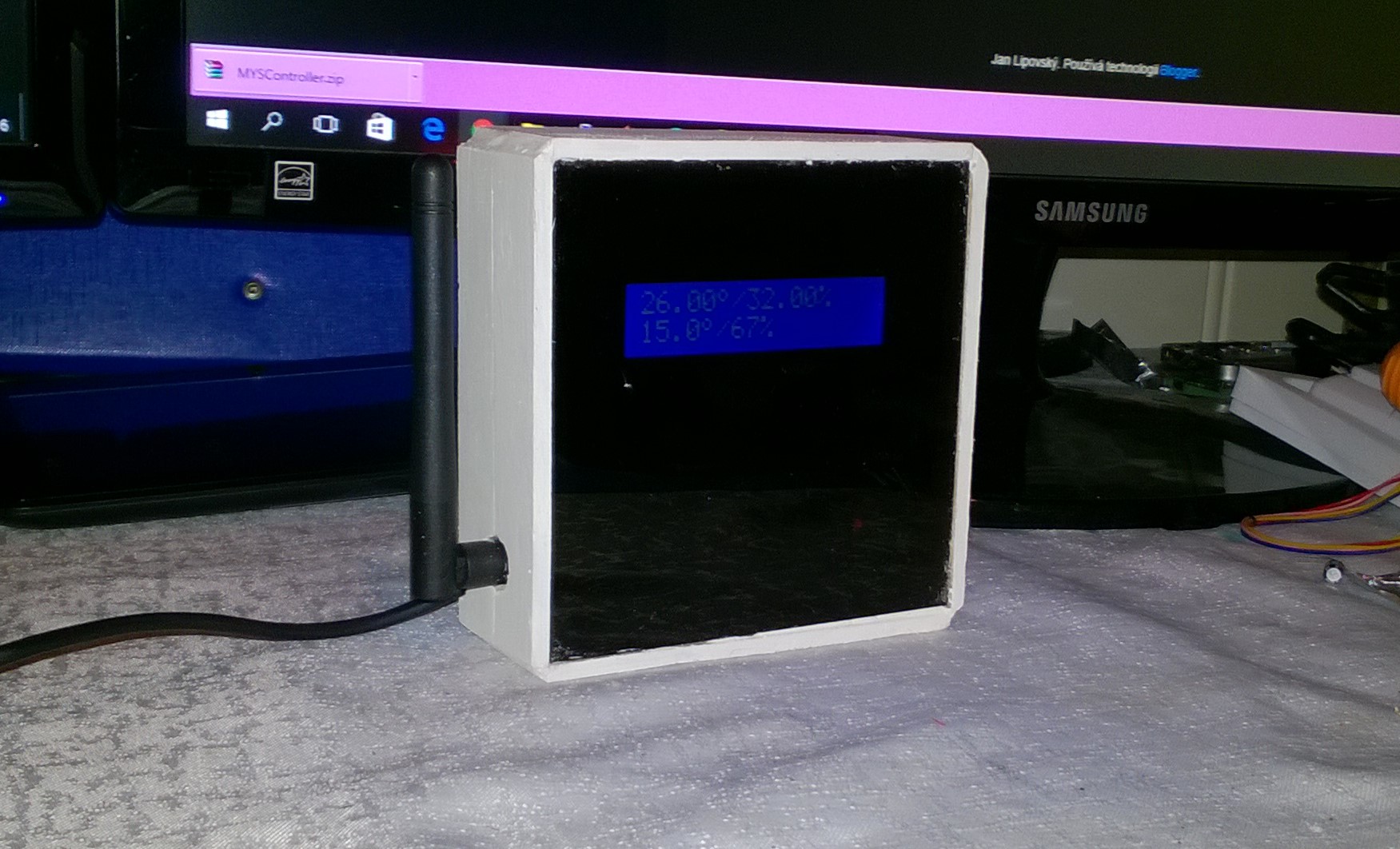
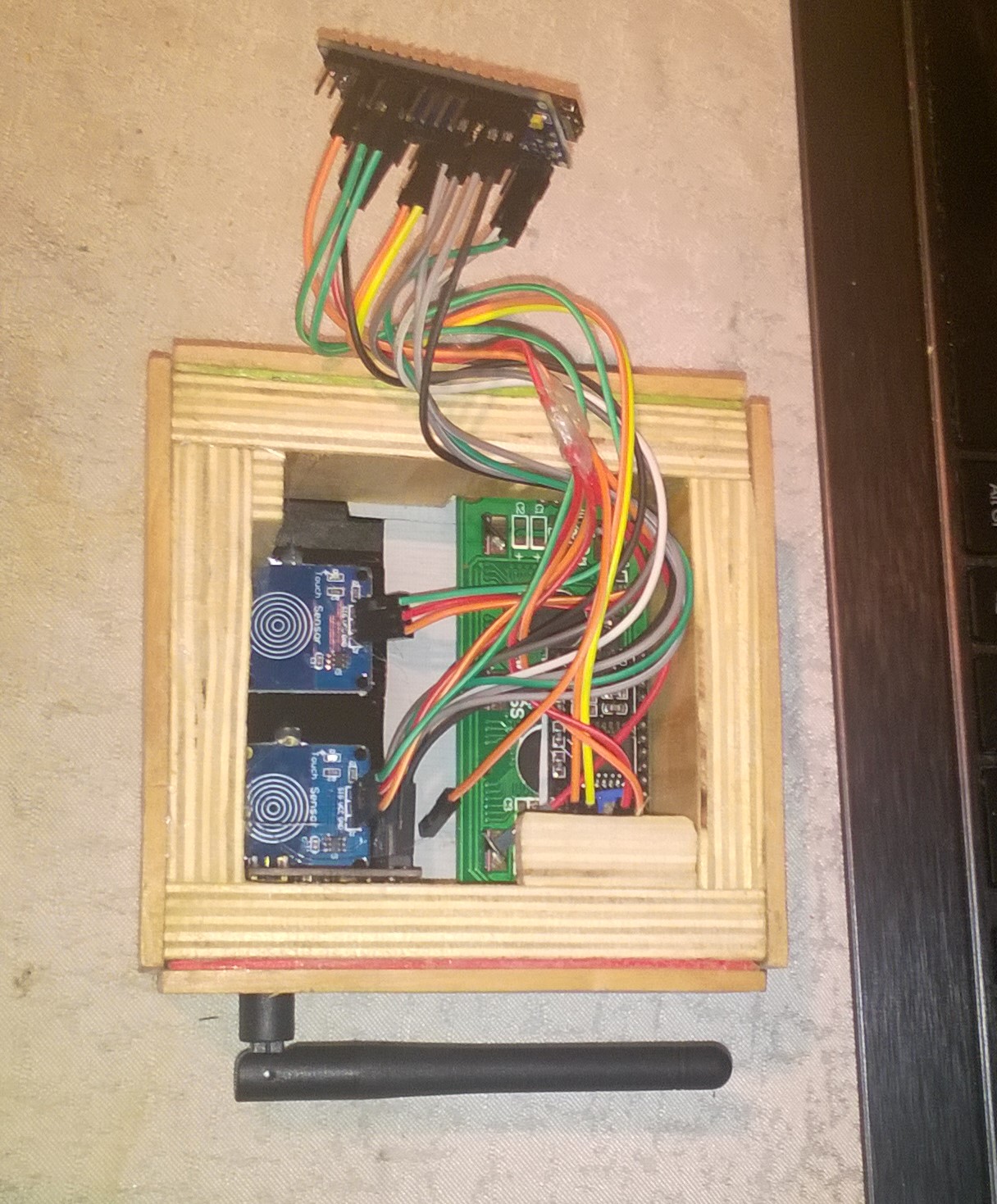
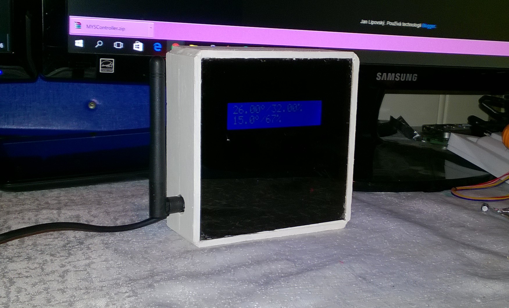
    • RE: livolo Glass Panel Touch Light Wall Switch + arduino 433Mhz

      1_1468756025188_WP_20160716_22_14_16_Prok.jpg 0_1468756025187_WP_20160709_22_07_06_Prok.jpg

      0_1468756052784_WP_20160716_22_14_16_Prok.jpg

      Im just about to finish this one, i use a black (transparrent) acrylic plate with touchmodules and LCD behind the acrylic.

      posted in My Project
      Tore André Rosander
      Tore André Rosander
    • RE: MySensors 2.0.0 Released

      Is there any plans to update the Raspberry gateway? The one where the nrf radio is connected directly to RPI gpio.
      As far as i know it is version 1.4 at the moment.

      posted in Announcements
      Tore André Rosander
      Tore André Rosander
    • RE: Laptop recommendation

      Isnt the only difference the cpu and the amount of RAM?

      The one with more RAM is slightly thicker (but also a bit cheaper), so it all comes down to size vs some extra ram.

      posted in General Discussion
      Tore André Rosander
      Tore André Rosander
    • RE: Problems with first sensors

      @blebbens

      The version 1.0 comes from this piece of code and has nothing to do with the mysensors version.

      void presentation()  {
        // Send the sketch version information to the gateway and Controller
        sendSketchInfo("Motion Sensor", "1.0");
      

      It would be nice to see the serial output from your node when you connect it to your gateway.
      Also try to comment out the sleep function so there is less code that could cause a problem.

      posted in Troubleshooting
      Tore André Rosander
      Tore André Rosander
    • RE: Choosing the right controller, how

      I know this one works on my nano:

      /**
       * The MySensors Arduino library handles the wireless radio link and protocol
       * between your home built sensors/actuators and HA controller of choice.
       * The sensors forms a self healing radio network with optional repeaters. Each
       * repeater and gateway builds a routing tables in EEPROM which keeps track of the
       * network topology allowing messages to be routed to nodes.
       *
       * Created by Henrik Ekblad <henrik.ekblad@mysensors.org>
       * Copyright (C) 2013-2015 Sensnology AB
       * Full contributor list: https://github.com/mysensors/Arduino/graphs/contributors
       *
       * Documentation: http://www.mysensors.org
       * Support Forum: http://forum.mysensors.org
       *
       * This program is free software; you can redistribute it and/or
       * modify it under the terms of the GNU General Public License
       * version 2 as published by the Free Software Foundation.
       *
       *******************************
       *
       * REVISION HISTORY
       * Version 1.0 - Henrik Ekblad
       * 
       * DESCRIPTION
       * Motion Sensor example using HC-SR501 
       * http://www.mysensors.org/build/motion
       *
       */
      
      // Enable debug prints
      // #define MY_DEBUG
      
      // Enable and select radio type attached
      #define MY_RADIO_NRF24
      //#define MY_RADIO_RFM69
      
      #include <SPI.h>
      #include <MySensor.h>
      
      unsigned long SLEEP_TIME = 120000; // Sleep time between reports (in milliseconds)
      #define DIGITAL_INPUT_SENSOR 3   // The digital input you attached your motion sensor.  (Only 2 and 3 generates interrupt!)
      #define INTERRUPT DIGITAL_INPUT_SENSOR-2 // Usually the interrupt = pin -2 (on uno/nano anyway)
      #define CHILD_ID 1   // Id of the sensor child
      
      // Initialize motion message
      MyMessage msg(CHILD_ID, V_TRIPPED);
      
      void setup()  
      {  
        pinMode(DIGITAL_INPUT_SENSOR, INPUT);      // sets the motion sensor digital pin as input
      }
      
      void presentation()  {
        // Send the sketch version information to the gateway and Controller
        sendSketchInfo("Motion Sensor", "1.0");
      
        // Register all sensors to gw (they will be created as child devices)
        present(CHILD_ID, S_MOTION);
      }
      
      void loop()     
      {     
        // Read digital motion value
        boolean tripped = digitalRead(DIGITAL_INPUT_SENSOR) == HIGH; 
              
        Serial.println(tripped);
        send(msg.set(tripped?"1":"0"));  // Send tripped value to gw 
       
        // Sleep until interrupt comes in on motion sensor. Send update every two minute. 
        sleep(INTERRUPT,CHANGE, SLEEP_TIME);
      }
      
      posted in Controllers
      Tore André Rosander
      Tore André Rosander
    • RE: Choosing the right controller, how

      @blebbens This should mean that the gateway is responding "Mysensors: Gateway ready (version 1.5.4)."

      What does the serial monitor say if you start the node when connected to the computer?

      In domoticz -> setup -> settings, is "allow new hardware" activated?

      posted in Controllers
      Tore André Rosander
      Tore André Rosander
    • RE: MySensors 2.0.0 Released

      I have been using the beta for some time now, to use the stable version do i just download the zip from github and replace the mysensors folder in arduino -> libraries ?

      posted in Announcements
      Tore André Rosander
      Tore André Rosander
    • RE: Choosing the right controller, how

      @blebbens Can you see it in setup -> devices?

      When you connect your node, does the log show anything?

      posted in Controllers
      Tore André Rosander
      Tore André Rosander
    • Omron D6T Series MEMS Thermal Sensors

      Does anyone have any experience with this type of sensor?

      http://no.mouser.com/search/refine.aspx?Ntk=P_MarCom&Ntt=103485542
      Datasheet: http://www.mouser.com/ds/2/307/D6T_datasheet_Nov2012-237760.pdf

      Its a Thermal sensor (4.5-5.5V with digital signals) that basicly is a firedetector, presencedetector (no motion is required) and temperature sensor in one sensor.

      Would this be possible to use with mysensros/arduino?

      It looks pretty impressive
      Evaluation D6T Omron thermal sensor – 02:31
      — StaringLizard

      EDIT: Just found another post on this forum regarding the same sensor.

      posted in Hardware
      Tore André Rosander
      Tore André Rosander
    • RE: Choosing the right controller, how

      https://forum.mysensors.org/topic/2437/step-by-step-procedure-to-connect-the-nrf24l01-to-the-gpio-pins-and-use-the-raspberry-as-a-serial-gateway

      You can also add custom themes, right now im setting up this one for my wall mounted tablet(search the domoticz forum for FLatz frontpage)

      0_1468222886977_upload-c7ac97c8-000a-40f8-a005-0ccbc9eb8596

      0_1468222920061_upload-c2753e6f-b177-4e83-b8cb-bee9fdf57ce0

      posted in Controllers
      Tore André Rosander
      Tore André Rosander
    • RE: Choosing the right controller, how

      What gateway are you using? You can add the MySensors under the "Setup" -> "Hardware" tab in domoticz.

      0_1468154446544_upload-fa53f869-97a4-416b-94d3-a269bc06b0f9

      If you have one that has LAN interface you can just add the IP adress and port, i use the piSerialGateway and have my nrf chip directly connected to the GPIO on my RPi.

      When you have added the Gateway all your nodes and their children get listed under "Hardware" -> "MySensros"

      0_1468154738218_upload-21be4a0e-b3e8-4775-96c7-7a14d413d84a

      After the Hardware is added and the nodes have connected you can enable and disable each child under "Setup" -> "Devices" as i shown in the picture a few posts ago.

      posted in Controllers
      Tore André Rosander
      Tore André Rosander
    • RE: Choosing the right controller, how

      @blebbens said:

      I take a look at domoticz, never heard of it.

      I found mysensors page of controllers and those screenshots. Those screenshots do not tell me how easy it is to use the software. They also do not tell me if I have to be able to program it by myself. Seeing OpenHAB screenshots, I thought they give me a nice GUI, but there I have to create the whole interface by myself from the beginning without some sort of settings etc.

      Hope, domoticz, vera or PiMatic are different. Does anybody use a controller without programming skills?

      When you add your gateway as "hardware" in domoticz and connect your nodes they will be discovered by domoticz.
      In your device list all the childs of every node will be listed and with one click you can add them to the system.

      0_1468139323352_domoticz9.png

      Here you can see my latest mysensors node that was added yesterday, if you click the green arrow you can add the child to your system.

      0_1468139386691_domoticz11.png

      Here is one of my scenes that activate some of my mysensors moodlights, "Fargelys", and the two "RGB Stue" devices is mysensors nodes. You can set the level (if its dimmers) and on/off delays).
      You can also press the "Add device" if you want a button, scenecontroller, motion detector etc to activate the scene.

      You can use blockly to do some logic, in the example under a device that was named "16" (used to be my livingroom lights) is turned off when i start a movie in kodi.

      0_1468139734238_domoticz12.png

      posted in Controllers
      Tore André Rosander
      Tore André Rosander
    • RE: Choosing the right controller, how

      I started with OpenHAB, but those kind of controllers is for people who like the programing part of the whole smarthouse thing.
      Now i use Domoticz and it solves all of my demands, LUA and Blockly for custom scripts (also possible to use python etc)
      Good hardware support, some good custom dashboards (for wall mounted tablets etc) and good community support (some of the main developers is also using mysensors).

      posted in Controllers
      Tore André Rosander
      Tore André Rosander
    • RE: Meet in Malmö, Summer 2016?

      I cant belive i missed this topic. Count me in next time, a perfect time to drop the kids off at their grandparents house in falkenberg on the way down and take home some cheap bacon, beer and sigaretts on the way home (norway) 😉 Its a win, win, win situation.

      A bit dissapointed that the bbq was not rigged with mysensors 😕 hehe

      posted in General Discussion
      Tore André Rosander
      Tore André Rosander
    • RE: Nice push buttons?

      @mfalkvidd I use those touch modules on every node that needs a button, i did have a node with haptic feedback. I just used an iphone vibrator and sent a short pulse to it when one of the touchbuttons was pressed.

      posted in Hardware
      Tore André Rosander
      Tore André Rosander
    • How does the S_SCENE_CONTROLLER work?

      Im building a scene controller with touch modules as buttons.

      Right now i have 2 buttons that is presented as S_SCENE_CONTROLLER

        present(CHILD_ID_3, S_SCENE_CONTROLLER); // Present button
        present(CHILD_ID_4, S_SCENE_CONTROLLER); // Present button 
      

      I want to make each button activate a specified scene.
      At first i tried to use this:

      MyMessage msg1(CHILD_ID_3,V_SCENE_ON); // Added message for buttons
      MyMessage msg2(CHILD_ID_4,V_SCENE_ON); // Added message for buttons
      

      I then added the node to domoticz and i got 3 devices (the node as scenecontroller and 2 devices that represent each button), i added each button as scene activators for different scenes.

      The problem is that i can only activate a scene once, so i edited my sketch to use these messages:

      MyMessage msg1(CHILD_ID_3,V_SCENE_ON); // Added message for buttons
      MyMessage msg2(CHILD_ID_4,V_SCENE_OFF); // Added message for buttons
      

      Now i can activate the scene, but i need to use my second button to deactivate it before i can activate it again.

      In domoticz its no need to deactivate scenes since turning a scene off does nothing (groups can be tuned on and off).

      How do i add a V_SCENE_OFF to the same button that sends V_SCENE_ON?

      posted in Development
      Tore André Rosander
      Tore André Rosander
    • RE: Can someone check my code? Please :)

      @TheoL said:

      I would strip the complete sketch and leave only the button part in it. That way it's much easier to detect if there's any mistake. It's really hard to help you with a sketch if this size.

      You could try to give the debouncer a higher interval, e.g.:
      debouncer2.interval(25);

      Thanks for the troubleshooting tip!

      @mfalkvidd After commenting out almost all of the LCD/temp functions i was left with the last wait that caused the problems, it seems to be working now but havent got the time to run it more than a few minutes.

      posted in Development
      Tore André Rosander
      Tore André Rosander
    • Can someone check my code? Please :)

      I am trying to put togheter a scenecontroller with LCD display, so far i have started with a sketch made by Gizmocuz over at the domoticz forum for the LCD display (standard 16x2 lcd).

      I did remove some code from the original LCD sketch (powermeter, water etc) and added another temperature sensor to be displayed on the LCD and added some code for my buttons.

      Im not a programmer so i dont realy know what every line of code do and i suspect that something is blocking my buttons. I use touch button modules, but i have to touch the module 10-20 times before it is sent to the controller. The modules works on my ESP so i dont think its a hardware problem.

      Can someone at least point me in the right direction?

      /* LCDDisplay 
       16 character 2 line I2C Display
       Backpack Interface labelled "A0 A1 A2" at lower right.
       ..and
       Backpack Interface labelled "YwRobot Arduino LCM1602 IIC V1"
       MOST use address 0x27, a FEW use 0x3F
      */ 
      
      // Enable debug prints to serial monitor
      #define MY_DEBUG 
      
      // Enable and select radio type attached
      #define MY_RADIO_NRF24
      
      #define MY_NODE_ID 23
      
      #include <Bounce2.h> // Added for button debounce
      #include <SPI.h>
      #include <MySensor.h> 
      #include <Wire.h>
      #include <LiquidCrystal_I2C.h>
      
      // Added buttons
      #define BUTTON_PIN_1  3  // Arduino Digital I/O pin number for button 
      #define BUTTON_PIN_2  4  // Arduino Digital I/O pin number for button 
      
      #define CHILD_ID 1                              // Id of the sensor child 
      #define CHILD_ID_3 2 // Button 1
      #define CHILD_ID_4 3 // Button 2
      
      Bounce debouncer1 = Bounce(); // Added debounce x2
      Bounce debouncer2 = Bounce();
      
      int oldValue1=-1; // Added for buttons
      int oldValue2=-1;
      
      unsigned long POLL_FREQUENCY_TEMP = 600000; // Minimum time between send (in milliseconds). We don't want to spam the gateway.
      unsigned long POLL_FREQUENCY_TEMP2 = 600000;  // Added for temp2
      
      MyMessage pollRequestMsg(CHILD_ID,V_CUSTOM);
      MyMessage msg1(CHILD_ID_3,V_LIGHT); // Added message for buttons
      MyMessage msg2(CHILD_ID_4,V_LIGHT); // Added message for buttons
      
      #define ID_TEMP_HUM_SENSOR_OUTSIDE 7
      #define ID_TEMP_HUM_SENSOR_OUTSIDE2 20
      
      // set the LCD address to 0x27 for a 16 chars 2 line display
      // A FEW use address 0x3F
      // Set the pins on the I2C chip used for LCD connections:
      //                    addr, en,rw,rs,d4,d5,d6,d7,bl,blpol
      LiquidCrystal_I2C lcd(0x3f, 2, 1, 0, 4, 5, 6, 7, 3, POSITIVE);  // Set the LCD I2C address
      #define LCD_WIDTH 16
      #define LCD_HEIGHT 2
      
      // Creat a set of new characters
      byte cdegrees[8] = {
        0b01100,
        0b10010,
        0b10010,
        0b01100,
        0b00000,
        0b00000,
        0b00000,
        0b00000
      };
      
      unsigned long lastTempPolled=0;
      unsigned long lastTempPolled2=0; // Added for temp2
      String lastTemp;
      String lastHum;
      String lastTemp2; // Added for temp2
      String lastHum2; // Added for temp2
      bool tempReceived=false;
      bool tempReceived2=false; // Added for temp2
      
      void CenterString(String &inText, const int width)
      {
        int osize=inText.length();
        if (osize>=width)
          return;
        int padLeft=(width-osize)/2;
        for (int ii=0; ii<padLeft; ii++)
        {
          inText=" " + inText;
        }
        while (inText.length()<width)
        {
          inText=inText+" ";
        }
      }
      
      String SpaceStrings(const String &lString, const String &rString)
      {
        String lText=lString;
        int ibc = LCD_WIDTH - lText.length() - rString.length();
        while (ibc>0) {
          lText+=" ";
          ibc--;
        }
        lText+=rString;
        return lText;
      }
      
      void setup()
      {
      // Added for buttons
      pinMode(BUTTON_PIN_1,INPUT);
      pinMode(BUTTON_PIN_2,INPUT);
      
      // Activate internal pull-up
      digitalWrite(BUTTON_PIN_1,HIGH);
      digitalWrite(BUTTON_PIN_2,HIGH);
      
      // After setting up the button, setup debouncer
      debouncer1.attach(BUTTON_PIN_1);
      debouncer1.interval(5);
      
      debouncer2.attach(BUTTON_PIN_2);
      debouncer2.interval(5);
      
        lastTemp="-";
        lastHum="-";
        lastTemp2="-";
        lastHum2="-";
      
        lcd.begin(LCD_WIDTH,LCD_HEIGHT);   // initialize the lcd for 16 chars 2 lines, turn on backlight
        
        lcd.createChar (1, cdegrees);    // load character to the LCD
        
        lcd.backlight();
      
        lcd.home ();                   // go home
      
        String sText;
        sText="Velkommen";
        CenterString(sText, LCD_WIDTH);
        lcd.print(sText);
        lcd.setCursor ( 0, 1 );        // go to the next line
        sText="Vennligst vent...";
        CenterString(sText, LCD_WIDTH);
        lcd.print(sText);
        wait(1000);
      }
      
      void presentation()  {
        // Send the sketch version information to the gateway and Controller
        sendSketchInfo("LCD Display", "1.0");
        wait (400); // Added wait to solve problem with st=fail
        present(CHILD_ID_3, S_LIGHT); // Present button
        wait (400); // Added wait to solve problem with st=fail
        present(CHILD_ID_4, S_LIGHT); // Present button
      }
      
      void loop()
      {
        debouncer1.update();
      // Get the update value
      int value1 = debouncer1.read();
      
      if (value1 != oldValue1) {
      // Send in the new value
      send(msg1.set(value1==HIGH ? 1 : 0));
      oldValue1 = value1;
      }
      
      debouncer2.update();
      // Get the update value
      int value2 = debouncer2.read();
      if (value2 != oldValue2) {
      
      // Send in the new value
      send(msg2.set(value2==HIGH ? 1 : 0));
      oldValue2 = value2;
      }
        unsigned long currentTime = millis();
        if ((!tempReceived)||((currentTime - lastTempPolled > POLL_FREQUENCY_TEMP)))
        {
          lastTempPolled = currentTime;
          //Request the temperature sensor
          send(pollRequestMsg.set(ID_TEMP_HUM_SENSOR_OUTSIDE));
          wait(500);
        }
          if ((!tempReceived2)||((currentTime - lastTempPolled2 > POLL_FREQUENCY_TEMP2)))
        {
          lastTempPolled2 = currentTime;
          //Request the temperature sensor
          send(pollRequestMsg.set(ID_TEMP_HUM_SENSOR_OUTSIDE2));
          wait(500);
        }
      wait(5000);
      }
      
      void PrintTempHumWater()
      {
        lcd.setCursor ( 0, 0 );
        String lText,rText;
        // lText="Inne:";
        lText=lastTemp;
        lText+=char(1);
        lText+="/";
        lText+=lastHum;
        lText+="%";
        
        // rText=lastWater;
        // rText+=" L";
        String outString=SpaceStrings(lText,rText);
        lcd.print(outString);
      }
      
      void PrintTempHumWater2()
      {
        lcd.setCursor ( 0, 1 );
        String lText,rText;
        lText="Ute:";
        lText=lastTemp2;
        lText+=char(1);
        lText+="/";
        lText+=lastHum2;
        lText+="%";
        
        // rText=lastWater;
        // rText+=" L";
        String outString=SpaceStrings(lText,rText);
        lcd.print(outString);
      }
      
      String getValue(String data, char separator, int index)
      {
        int found = 0;
        int strIndex[] = {0, -1  };
        int maxIndex = data.length()-1;
        for(int i=0; i<=maxIndex && found<=index; i++){
          if(data.charAt(i)==separator || i==maxIndex){
            found++;
            strIndex[0] = strIndex[1]+1;
            strIndex[1] = (i == maxIndex) ? i+1 : i;
          }
        }
        return found>index ? data.substring(strIndex[0], strIndex[1]) : "";
      }
      
      void receive(const MyMessage &message) {
        if (message.type==V_CUSTOM) {
          String cMessage =  message.getString();
          int idx = getValue(cMessage, '#', 0).toInt();
          if (idx == ID_TEMP_HUM_SENSOR_OUTSIDE) {
            //0,temp,hum,humstatus
            tempReceived=true;
            lastTemp=getValue(cMessage, '#', 2);
            lastHum=getValue(cMessage, '#', 3);
            PrintTempHumWater();
          }
          else if (idx == ID_TEMP_HUM_SENSOR_OUTSIDE2) {
            //0,temp,hum,humstatus
            tempReceived2=true;
            lastTemp2=getValue(cMessage, '#', 2);
            lastHum2=getValue(cMessage, '#', 3);
            PrintTempHumWater2();
          }
          else {
            Serial.print("Received unknown custom message from gw:");
            Serial.println(cMessage);
          }
        }
      }```
      posted in Development
      Tore André Rosander
      Tore André Rosander
    • RE: In wall LCD Switch/Scene controller for MySensors

      Is it possible to do something similar with the smaller LCDs? Like the 2x16 ones?

      posted in OpenHardware.io
      Tore André Rosander
      Tore André Rosander
    • RE: Wall mounted 'mood light'

      @AWI Is this code for version 1.5?
      Im trying to compile it for the dev (v2) but i get a lot of errors.
      Mostly alot of code that "was not declared in this scope".

      EDIT: Just found your link to the "Conversion guide", will have look at it!

      posted in My Project
      Tore André Rosander
      Tore André Rosander
    • RE: looking for solid core soldering wire

      In sweden this should be available on Clas ohlson, but you should be able to get this at almost any store that sells electric components.

      posted in General Discussion
      Tore André Rosander
      Tore André Rosander
    • RE: Sketch for Lightning Sensor

      @alexsh1 What i read when researching this chip it can be placed inside.

      @Sparkman Nice, i see that it has a detection range about 40km so thats already a pretty good distance to get a notification when lightning is detected.

      posted in Development
      Tore André Rosander
      Tore André Rosander
    • RE: Sketch for Lightning Sensor

      Is it possible to detect the distance to the lightningstrike?
      I was thinking to get some sort of detector to notify me if there is ligning registered X km away from my home.

      posted in Development
      Tore André Rosander
      Tore André Rosander
    • RE: Air Quality Sensor

      @epierre Hi! The dev branch (v 2) and the raspberry pi gateway (nrf24 directly connected to RPi GPIO). This is what i get in the serial console when i test with gas from a lighter:

      Starting sensor (RNNNA-, 2.0.0-beta)
      Radio init successful.
      find parent
      send: 255-255-255-255 s=255,c=3,t=7,pt=0,l=0,sg=0,st=bc:
      find parent
      send: 255-255-255-255 s=255,c=3,t=7,pt=0,l=0,sg=0,st=bc:
      read: 0-0-255 s=255,c=3,t=8,pt=1,l=1,sg=0:0
      parent=0, d=1
      req id
      send: 255-255-0-0 s=255,c=3,t=3,pt=0,l=0,sg=0,st=ok:
      req id
      send: 255-255-0-0 s=255,c=3,t=3,pt=0,l=0,sg=0,st=ok:
      read: 0-0-255 s=255,c=3,t=4,pt=0,l=2,sg=0:5
      
      send: 5-5-0-0 s=255,c=3,t=15,pt=0,l=2,sg=0,st=ok:
      send: 5-5-0-0 s=255,c=0,t=17,pt=0,l=10,sg=0,st=ok:2.0.0-beta
      send: 5-5-0-0 s=255,c=3,t=6,pt=1,l=1,sg=0,st=fail:0
      id=5
      Init complete, id=5, parent=0, distance=1
      0
      LPG:0ppm    CO:0ppm    SMOKE:0ppm
      0
      LPG:8ppm    CO:47ppm    SMOKE:18ppm
      send: 5-5-0-0 s=0,c=1,t=37,pt=2,l=2,sg=0,st=ok:95
      0
      LPG:0ppm    CO:0ppm    SMOKE:0ppm
      send: 5-5-0-0 s=0,c=1,t=37,pt=2,l=2,sg=0,st=ok:0```
      posted in Hardware
      Tore André Rosander
      Tore André Rosander
    • RE: Air Quality Sensor

      How do i get the Airquality sensor to show in domoticz? I use the AirQuality example from the library and MQ2.
      I can see that it works in the serial, and it shows as a node under the mysensors hardware, but nothing in log or the device list when i expose it for gas.

      0_1466081228162_upload-0f9ebe47-10d5-446c-a3bd-24c1649c94c1

      posted in Hardware
      Tore André Rosander
      Tore André Rosander
    • How to use the Selector switch with mysensors

      Hello again!

      Is it possible to use the selector switch in domoticz with mysensors?

      I found the IR sender sketch on this forum, the sketch present it selfe as a light switch and i can set what IR codes to be sent when turning the switch on and off.

      Im going to controll my tv and i need to be able to send at least 5-6 different IR codes with my node so using the selector switch would be the best choice i think.

      Heres the code i am going to use

      /**
       * The MySensors Arduino library handles the wireless radio link and protocol
       * between your home built sensors/actuators and HA controller of choice.
       * The sensors forms a self healing radio network with optional repeaters. Each
       * repeater and gateway builds a routing tables in EEPROM which keeps track of the
       * network topology allowing messages to be routed to nodes.
       *
       * Created by Henrik Ekblad <henrik.ekblad@mysensors.org>
       * Copyright (C) 2013-2015 Sensnology AB
       * Full contributor list: https://github.com/mysensors/Arduino/graphs/contributors
       *
       * Documentation: http://www.mysensors.org
       * Support Forum: http://forum.mysensors.org
       *
       * This program is free software; you can redistribute it and/or
       * modify it under the terms of the GNU General Public License
       * version 2 as published by the Free Software Foundation.
       *
       *******************************
       *
       * REVISION HISTORY
       * Version 1.0 - Henrik EKblad
       * 
       * DESCRIPTION
       * Example sketch showing how to control ir devices
       * An IR LED must be connected to Arduino PWM pin 3.
       * An optional ir receiver can be connected to PWM pin 8. 
       * All receied ir signals will be sent to gateway device stored in VAR_1.
       * When binary light on is clicked - sketch will send volume up ir command
       * When binary light off is clicked - sketch will send volume down ir command
       * http://www.mysensors.org/build/ir
       */
      
      #include <MySensor.h>
      #include <SPI.h>
      #include <IRLib.h>
      #define MY_RADIO_NRF24
      //#define MY_RADIO_RFM69
      int RECV_PIN = 8;
      
      #define CHILD_1  3  // childId
      
      IRsend irsend;
      IRrecv irrecv(RECV_PIN);
      IRdecode decoder;
      //decode_results results;
      unsigned int Buffer[RAWBUF];
      MySensor gw;
      MyMessage msg(CHILD_1, V_VAR1);
      
      void setup()  
      {  
        irrecv.enableIRIn(); // Start the ir receiver
        decoder.UseExtnBuf(Buffer);
        gw.begin(incomingMessage);
      
        // Send the sketch version information to the gateway and Controller
        gw.sendSketchInfo("IR Sensor", "1.0");
      
        // Register a sensors to gw. Use binary light for test purposes.
        gw.present(CHILD_1, S_LIGHT);
      }
      
      
      void loop() 
      {
        gw.process();
        if (irrecv.GetResults(&decoder)) {
          irrecv.resume(); 
          decoder.decode();
          decoder.DumpResults();
              
          char buffer[10];
          sprintf(buffer, "%08lx", decoder.value);
          // Send ir result to gw
          gw.send(msg.set(buffer));
        }
      }


      void incomingMessage(const MyMessage &message) {
        // We only expect one type of message from controller. But we better check anyway.
        if (message.type==V_LIGHT) {
           int incomingRelayStatus = message.getInt();
           if (incomingRelayStatus == 1) {
            irsend.send(NEC, 0x2AA22DD, 32); // Vol up yamaha ysp-900
           } else {
            irsend.send(NEC, 0x1EE1F807, 32); // Vol down yamaha ysp-900
           }
           // Start receiving ir again...
          irrecv.enableIRIn(); 
        }
      }
          
      // Dumps out the decode_results structure.
      // Call this after IRrecv::decode()
      // void * to work around compiler issue
      //void dump(void *v) {
      //  decode_results *results = (decode_results *)v
      /*void dump(decode_results *results) {
        int count = results->rawlen;
        if (results->decode_type == UNKNOWN) {
          Serial.print("Unknown encoding: ");
        } 
        else if (results->decode_type == NEC) {
          Serial.print("Decoded NEC: ");
        } 
        else if (results->decode_type == SONY) {
          Serial.print("Decoded SONY: ");
        } 
        else if (results->decode_type == RC5) {
          Serial.print("Decoded RC5: ");
        } 
        else if (results->decode_type == RC6) {
          Serial.print("Decoded RC6: ");
        }
        else if (results->decode_type == PANASONIC) {  
          Serial.print("Decoded PANASONIC - Address: ");
          Serial.print(results->panasonicAddress,HEX);
          Serial.print(" Value: ");
        }
        else if (results->decode_type == JVC) {
           Serial.print("Decoded JVC: ");
        }
        Serial.print(results->value, HEX);
        Serial.print(" (");
        Serial.print(results->bits, DEC);
        Serial.println(" bits)");
        Serial.print("Raw (");
        Serial.print(count, DEC);
        Serial.print("): ");
      
        for (int i = 0; i < count; i++) {
          if ((i % 2) == 1) {
            Serial.print(results->rawbuf[i]*USECPERTICK, DEC);
          } 
          else {
            Serial.print(-(int)results->rawbuf[i]*USECPERTICK, DEC);
          }
          Serial.print(" ");
        }
        Serial.println("");
      }
      */```
      posted in Development
      Tore André Rosander
      Tore André Rosander
    • RE: Step-by-step procedure to connect the NRF24L01+ to the GPIO pins and use the Raspberry as a Serial Gateway (MySensors 1.x)

      @jpbabou That is the Message of the day (motd) and you can edit it to fit your needs.
      This guide should work on debian weezy and jessie
      https://oitibs.com/debian-wheezy-dynamic-motd/

      posted in Hardware
      Tore André Rosander
      Tore André Rosander
    • RE: Step-by-step procedure to connect the NRF24L01+ to the GPIO pins and use the Raspberry as a Serial Gateway (MySensors 1.x)

      @hek But insted of including heartbeats from every non sensor node (trying to keep 2.4 ghz traffic to a minimum), can i solve this by using an arduino repeater node? So the repeater knows the network map and sends heartbeat to the gateway.

      posted in Hardware
      Tore André Rosander
      Tore André Rosander
    • RE: Step-by-step procedure to connect the NRF24L01+ to the GPIO pins and use the Raspberry as a Serial Gateway (MySensors 1.x)

      I have some trouble with the gateway not storing the network map, if i restart the gateway my non-sensor nodes need to send some kind of heartbeat to reconnect to the gateway.

      Is this a known problem or is it something wrong with my setup?

      posted in Hardware
      Tore André Rosander
      Tore André Rosander
    • RE: Repeater questions

      @AWI The code is from the MySensors examples and i use it to control 3 mosfets that controls a ledstrip.

      I need the heartbeat because i use the RPi gateway with the NRF24 chip directly connected to the RPi, and the gateway software for the raspberry dont store the network map so if i reboot the RPi the nodes loose connection to the gateway.

      posted in Development
      Tore André Rosander
      Tore André Rosander
    • RE: Repeater questions

      How should i include the heartbeat function in this sketch? (or any other)

      /**
       * The MySensors Arduino library handles the wireless radio link and protocol
       * between your home built sensors/actuators and HA controller of choice.
       * The sensors forms a self healing radio network with optional repeaters. Each
       * repeater and gateway builds a routing tables in EEPROM which keeps track of the
       * network topology allowing messages to be routed to nodes.
       *
       * Created by Henrik Ekblad <henrik.ekblad@mysensors.org>
       * Copyright (C) 2013-2015 Sensnology AB
       * Full contributor list: https://github.com/mysensors/Arduino/graphs/contributors
       *
       * Documentation: http://www.mysensors.org
       * Support Forum: http://forum.mysensors.org
       *
       * This program is free software; you can redistribute it and/or
       * modify it under the terms of the GNU General Public License
       * version 2 as published by the Free Software Foundation.
       *
       *******************************
       *
       * REVISION HISTORY
       * Version 1.0 - Created by vil1driver
       * 
       * DESCRIPTION
       * RGB led strip controled with three dimmers + one On/Off for run/stop rgb color cycle :p
       * 
       */
       
      #define SN   "RGB Led strip 3D"
      #define SV   "v1"
      
      // Enable debug prints to serial monitor
      #define MY_DEBUG 
      
      // Enable and select radio type attached
      #define MY_RADIO_NRF24
      //#define MY_RADIO_RFM69
      
      #include <SPI.h>
      #include <MySensor.h>	
      
      // Arduino pin attached to MOSFET Gate pin
      #define RED_PIN 3 	
      #define GREEN_PIN 5
      #define BLUE_PIN 6
      
      // Define message name and type to send sensor info
      MyMessage RedStatus(RED_PIN, V_DIMMER);		
      MyMessage GreenStatus(GREEN_PIN, V_DIMMER);
      MyMessage BlueStatus(BLUE_PIN, V_DIMMER);
      MyMessage Status(1, V_DIMMER);
      MyMessage rgbShowState(0, V_LIGHT);
          
      // Serial.print translate sensor id to sensor name
      char color[][6] = {"","","","RED","","GREEN","BLUE"};	
         
      // Vars for rgbShow function
      int redval = 0;
      int greenval = 0;
      int blueval = 0;
      long time=0;
      int isShow;
           
      void setup() 
      {
        // Define pin mode (pin number, type)
        pinMode(RED_PIN, OUTPUT);		
        pinMode(GREEN_PIN, OUTPUT);
        pinMode(BLUE_PIN, OUTPUT);
      
        // Correct saved RGB value for first start
        saveState(RED_PIN, constrain((int8_t)loadState(RED_PIN), 0, 100)); 
        saveState(GREEN_PIN, constrain((int8_t)loadState(GREEN_PIN), 0, 100)); 
        saveState(BLUE_PIN, constrain((int8_t)loadState(BLUE_PIN), 0, 100)); 
                   
        // Get value from eeprom and write to output
        analogWrite(RED_PIN, 255 * loadState(RED_PIN) / 100); 		
        analogWrite(GREEN_PIN, 255 * loadState(GREEN_PIN) / 100);
        analogWrite(BLUE_PIN, 255 * loadState(BLUE_PIN) / 100);
               
        // Write some debug info
        Serial.print("Load from eeprom RED: "); 
        Serial.print(loadState(RED_PIN)); 
        Serial.println("%"); 
        Serial.print("Load from eeprom GREEN: "); 
        Serial.print(loadState(GREEN_PIN)); 
        Serial.println("%"); 
        Serial.print("Load from eeprom BLUE: "); 
        Serial.print(loadState(BLUE_PIN)); 
        Serial.println("%");  
        
        // Send RGB value to controler (request ack back: true/false)
        Serial.println("Send eeprom value to controler"); 
        send( RedStatus.set(loadState(RED_PIN)), false );    
        send( GreenStatus.set(loadState(GREEN_PIN)), false );
        send( BlueStatus.set(loadState(BLUE_PIN)), false );
        
        // Correct RGB show state for first start and load it (set to 'On' at first start)
        saveState(0, constrain((int8_t)loadState(0), 0, 1));
        isShow=loadState(0);
             
        // Send RGB show state to controler (request ack back: true/false)
        send( rgbShowState.set(isShow), false);
        
        if (isShow==1){Serial.println("RGB show running..."); }
        Serial.println("Ready to receive messages...");  
      }
      
      void presentation()  {
        // Present sketch (name, version)
        sendSketchInfo(SN, SV);        
             
        // Register sensors (id, type, description, ack back)
        present(RED_PIN, S_DIMMER, "present RED light", false);
        present(GREEN_PIN, S_DIMMER, "present GREEN light", false);
        present(BLUE_PIN, S_DIMMER, "present BLUE light", false);
        present(0, S_LIGHT, "present Show button", false);
      }
      
      void loop()
      {
        // Run RGB show if is set
        if (isShow==1)
        {
          	rgbShow();
        	analogWrite(RED_PIN, redval);
        	analogWrite(GREEN_PIN, greenval);
        	analogWrite(BLUE_PIN, blueval);
         } 
      }
      
      
      void receive(const MyMessage &message)
      {
        if (message.isAck())
        {
         	Serial.println("Got ack from gateway");
        }
        if (message.type == V_LIGHT)
        {
        	// Incoming on/off command sent from controller ("1" or "0")
        	int lightState = message.getString()[0] == '1';
        
        	// if receive RGB Show On commands, start the show
        	if (message.sensor==0 && lightState==1){ rgbShowOn();	}
              // if receive RGB Show Off commands, stop the show
        	else if (message.sensor==0 && lightState==0){	rgbShowOff();	}
             
        	// if receive RGB switch On command
        	else if (lightState==1)
        	{
        		// Write some debug info
                	Serial.print("Incoming change for ");
                	Serial.print(color[message.sensor]);
                	Serial.println(": On");
                	Serial.print("Load from eeprom: ");
                
        		if ( loadState(message.sensor) == 0)
        		{
        			// Pick up last saved dimmer level from the eeprom
                  		analogWrite(message.sensor, 255 * loadState(10*message.sensor) / 100);
                  		// Save loaded value to current
                  		saveState(message.sensor, loadState(10*message.sensor));
                  		Serial.print(loadState(10*message.sensor)); 
                  		Serial.println("%");
                  		// Send value to controler
                  		Serial.println("Send value to controler");
                  		send(Status.setSensor(message.sensor).set(loadState(10*message.sensor)),false);
                	}
                	else
                	{
                  		// Pick up last saved dimmer level from the eeprom
                  		analogWrite(message.sensor, 255 * loadState(message.sensor) / 100);
                  		Serial.print(loadState(message.sensor));
                  		Serial.println("%"); 
                  		// Send value to controler
                  		Serial.println("Send value to controler");
                  		send(Status.setSensor(message.sensor).set(loadState(message.sensor)),false);
                	} 
                	// Stop the show if it's running
                	if (isShow==1){ rgbShowStop(message.sensor); }
              }
        	// if recieve switch Off command
        	else if (lightState==0)
        	{
        		// Write output to 0 (Off)
                	analogWrite(message.sensor, 0);
                	// Save old value to eeprom if it'was not zero
                	if ( loadState(message.sensor) != 0 )
                	{
                  		saveState(10*message.sensor, constrain((int8_t)loadState(message.sensor), 0, 100)); 
                	}
                	// Save new value to eeprom
                	saveState(message.sensor, 0); 
                	// Write some debug info
        		Serial.print("Incoming change for ");
        		Serial.print(color[message.sensor]);
        		Serial.print(": ");
        		Serial.println("Off");	
                	Serial.print("Store old value: ");
                	Serial.print(loadState(10*message.sensor));  
                	Serial.println("%");
                	// Send value to controler
                	Serial.println("Send value to controler");
                	send(Status.setSensor(message.sensor).set(loadState(message.sensor)),false);
        		// Stop the show if it's running
        		if (isShow==1){ rgbShowStop(message.sensor); }
        	}
        }
        else if (message.type == V_DIMMER)
        {    
          	uint8_t incomingDimmerStatus = message.getByte();
          	// limits range of sensor values to between 0 and 100 
          	incomingDimmerStatus = constrain((int8_t)incomingDimmerStatus, 0, 100);
          	// Change Dimmer level
          	analogWrite(message.sensor, 255 * incomingDimmerStatus / 100);
          	//Save value to eeprom
          	saveState(message.sensor, incomingDimmerStatus); 
          	// Write some debug info
          	Serial.print("Incoming change for ");
          	Serial.print(color[message.sensor]);
          	Serial.print(": ");
          	Serial.print(incomingDimmerStatus);
          	Serial.println("%");
              // Send value to controler
              Serial.println("Send value to controler");
              send(Status.setSensor(message.sensor).set(loadState(message.sensor)),false);
          	// Stop the show if it's running
          	if (isShow==1){ rgbShowStop(message.sensor); }
          }
      }
         
      void rgbShow()
      {
        time = millis();
        redval = 128+250*cos(2*PI/300000*time);
        greenval = 128+250*cos(2*PI/300000*time-222);
        blueval = 128+250*cos(2*PI/300000*time-111);
        // limits range of sensor values to between 0 and 255 
        redval = constrain(redval, 0, 255);
        greenval = constrain(greenval, 0, 255);
        blueval = constrain(blueval, 0, 255);
      }
      
      void rgbShowOn()
      {
        // define show On
        isShow=1;
        // Save state
        saveState(0, 1); 
        // Write some debug info
        Serial.println("Show must go on");
      }
         
      void rgbShowOff()
      {
        // define show Off
        isShow=0;
        // Save state
        saveState(0, 0);
        // Save RGB value to eeprom
        saveState(RED_PIN, 100 * redval / 255); 
        saveState(GREEN_PIN, 100 * greenval / 255);
        saveState(BLUE_PIN, 100 * blueval / 255);
        // Write some debug info
        Serial.println("Stop the show");
        // Send actual RGB value and state to controler and request ack back (true/false)
        Serial.println("Send eeprom value to controler"); 
        send( RedStatus.set(loadState(RED_PIN)), false );    
        send( GreenStatus.set(loadState(GREEN_PIN)), false );
        send( BlueStatus.set(loadState(BLUE_PIN)), false );
        send( rgbShowState.set(0), false);
      }
      
      void rgbShowStop(int sensor)
      {
         // define show Off
         isShow=0;
         // Save state
         saveState(0, 0);
         // Write some debug info
         Serial.println("Stop the show");
         // Send actual RGB value and state to controler and request ack back (true/false)
         Serial.println("Send eeprom value to controler"); 
         if (sensor != RED_PIN)
         {
              saveState(RED_PIN, 100 * redval / 255); 
              send( RedStatus.set(loadState(RED_PIN)), false );  
          }
          if (sensor != GREEN_PIN)
          {
              saveState(GREEN_PIN, 100 * greenval / 255); 
              send( GreenStatus.set(loadState(GREEN_PIN)), false );
          }
          if (sensor != BLUE_PIN)
          {
              saveState(BLUE_PIN, 100 * blueval / 255);
              send( BlueStatus.set(loadState(BLUE_PIN)), false );
          }
          send( rgbShowState.set(0), false);
      }


      posted in Development
      Tore André Rosander
      Tore André Rosander
    • RE: Could anyone look over this setup?

      @Tore-André-Rosander said:

      I have a working RGB-3D "sensor" up and running, but i am making a wall mounted lamp so i want to use the same power supply for my arduino as i use for the LED strip in the lamp to reduce the number of cables.

      With the transistors and volts and amps flying in every direction i get a bit confused, and i dont want to start a fire 😉
      Hardware:
      12V LED strip
      12V powersupply (500mah)

      Arduino Nano
      nrf24

      3x PN2222a transistors

      Right now all of my ground pins is taken 1 for the NRF24 and 1 for the ground/emitter of the transistors (also connected to the LED powersupply ground).

      My question is: Can something share ground?
      Can the nrf share common ground with the transistor and the powersupply?

      0_1463600037013_Untitled Sketefch 2_bb.png

      Thank you for your reply! I did a stresstest with my arduino connected to 12v (yes, i have a clone). It gets hot, but not so much that i burn my selfe when touching it.

      Will i notice right away if there is any danger with the arduino i am using or could it take days/weeks/months before a possible overheat takes place?

      posted in Hardware
      Tore André Rosander
      Tore André Rosander
    • Could anyone look over this setup?

      I have a working RGB-3D "sensor" up and running, but i am making a wall mounted lamp so i want to use the same power supply for my arduino as i use for the LED strip in the lamp to reduce the number of cables.

      With the transistors and volts and amps flying in every direction i get a bit confused, and i dont want to start a fire 😉
      Hardware:
      12V LED strip
      12V powersupply (500mah)

      Arduino Nano
      nrf24

      3x PN2222a transistors

      Right now all of my ground pins is taken 1 for the NRF24 and 1 for the ground/emitter of the transistors (also connected to the LED powersupply ground).

      My question is: Can something share ground?
      Can the nrf share common ground with the transistor and the powersupply?

      0_1463600037013_Untitled Sketefch 2_bb.png

      posted in Hardware
      Tore André Rosander
      Tore André Rosander
    • Nodes wont reconnect

      Hello!
      I have a few nodes that wont reconnect after reboot of the gateway.
      This is my setup:

      RPi 2 (debian jessie) and the PiGatewaySerial (as seen on the forum), i using the dev branch (v2) of mysensor nodes.

      If i reboot the Pi (with the gateway) my nodes wont reconnect to the gateway. The nodes is 2 arduino nanos with the RGB-3D (not edited) sketch from the example library.

      I dont know where to start troubleshoot.

      posted in Troubleshooting
      Tore André Rosander
      Tore André Rosander
    • RE: Step-by-step procedure to connect the NRF24L01+ to the GPIO pins and use the Raspberry as a Serial Gateway (MySensors 1.x)

      Does anyone know what this error is about?
      RPi2, NRF24l01, OSMC (Debian jessie), Domoticz v3.5051.

      osmc@osmc:~/Raspberry$ sudo make install
      Installing PiGatewaySerial to /usr/local/sbin
      Installing PiGateway to /usr/local/sbin
      Installing initscripts to /etc/init.d
      Installing syslog config to /etc/rsyslog.d
      Failed to restart rsyslog.service: Unit rsyslog.service failed to load: No such file or directory.
      Makefile:79: recipe for target 'install-initscripts' failed
      make: *** [install-initscripts] Error 6
      

      I can run the gateway even with the error, i can also add it to Domoticz and send/receive data.
      But after a few minutes i get a massive error in domoticz saying "(24) Too many files open" on every logentry and my domoticz loose connection to the Logitech mediaserver, remote Kodi hardware, mqtt server etc.

      osmc@osmc:~/Raspberry$ sudo ./PiGatewaySerial
      Starting PiGatewaySerial...
      Protocol version - 1.4
      Created PTY '/dev/pts/2'
      Gateway tty: /dev/ttyMySensorsGateway
      ================ SPI Configuration ================
      CSN Pin          = CE0 (PI Hardware Driven)
      CE Pin           = Custom GPIO25
      Clock Speed      = 8 Mhz
      ================ NRF Configuration ================
      STATUS           = 0x0e RX_DR=0 TX_DS=0 MAX_RT=0 RX_P_NO=7 TX_FULL=0
      RX_ADDR_P0-1     = 0xa8a8e1fc00 0xa8a8e1fc00
      RX_ADDR_P2-5     = 0xff 0xc4 0xc5 0xc6
      TX_ADDR          = 0xa8a8e1fc02
      RX_PW_P0-6       = 0x20 0x20 0x20 0x00 0x00 0x00
      EN_AA            = 0x3b
      EN_RXADDR        = 0x06
      RF_CH            = 0x4c
      RF_SETUP         = 0x23
      CONFIG           = 0x0e
      DYNPD/FEATURE    = 0x3f 0x06
      Data Rate        = 250KBPS
      Model            = nRF24L01+
      CRC Length       = 16 bits
      PA Power         = PA_LOW
      
      posted in Hardware
      Tore André Rosander
      Tore André Rosander
    • RE: RGB-3D only showing 1 dimmer, not 3 in Vera

      What is the actual solution to this problem? I have the same problem (mysensors v2 (dev)) and domoticz.
      I have 2 RBG-3D nodes, the first one is showing all dimmers and works perfect, but when i added the second one i only get "Present Blue" and the "show" button.

      Under the mysensors hardware in domoticz the second RGB node display "Name: unknown, Sketch name: Unknown".

      0_1462194784182_mysensors.png

      posted in Troubleshooting
      Tore André Rosander
      Tore André Rosander
    • RE: Wall mounted 'mood light'

      Im building the same light, but i use 12v LED strips controlled with mosfets. Is it possible to use the same scetch?

      posted in My Project
      Tore André Rosander
      Tore André Rosander
    • RE: IR Sender for stereo receiver

      Can you share the code?

      posted in My Project
      Tore André Rosander
      Tore André Rosander
    • RE: Domoticz as controller **and** a gateway for MySensor nodes running on a Raspberry Pi 2

      Is there any pros/cons for using the nrf directly on the RPi instead of a NodeMCU?

      Right now i use NodeMCU (esp) with nrf radio as gateway, but i want to reduce the nuber of units around my house so connecting directly to the RPi would be better as long as there is no negative sides to it.

      posted in My Project
      Tore André Rosander
      Tore André Rosander
    • RE: Step-by-step procedure to connect the NRF24L01+ to the GPIO pins and use the Raspberry as a Serial Gateway (MySensors 1.x)

      Hello, im just starting to set up some mysensors nodes and have already set up a gateway with nodemcu (esp).
      But to eliminate the number of devices i am thinking about moving the gateway directly to the Raspberry pi as mentioned in this thread. Is there any downsides (or upsides) by connecting the nrf24 chip directly to the RPI?

      And btw:
      "The radio module NRF24L01+ is cheap and power efficient, but it is unable to communicate with regular wifi."
      That is not entirely correct, the nrf24 can connecct to wifi and send TCP/IP packets with an arduino.

      posted in Hardware
      Tore André Rosander
      Tore André Rosander
    • RE: Curtain Control Node.

      Maybe its because i have not calibrated it? I dont have any pushbuttons laying around, so im gonna make one with some wires. But i see that there is two pins defined as buttons. Should i use the buttonPin1 as VCC?

      So it would look something like buttonPin1 -> buttonPin2 -> button -> gnd?

      posted in My Project
      Tore André Rosander
      Tore André Rosander
    • RE: Curtain Control Node.

      @AWI Seems like my problem is with Domoticz itselfe.
      I have the same problem as described in this post https://www.domoticz.com/forum/viewtopic.php?f=6&t=7748

      posted in My Project
      Tore André Rosander
      Tore André Rosander
    • RE: Curtain Control Node.

      @AWI THanks again for your fast replys!

      This is what i get in serial monitor when i use the "up" "down" buttons for blinds percentage in domoticz.

      This is my very first MySensor setup so it might be some error with my setup, i will have a deeper look at it later tonight.

      Starting sensor (RNNNA-, 2.0.0-beta)
      Radio init successful.
      State read: -1
      State read: -1
      send: 13-13-0-0 s=255,c=3,t=15,pt=0,l=2,sg=0,st=ok:
      send: 13-13-0-0 s=255,c=0,t=17,pt=0,l=10,sg=0,st=ok:2.0.0-beta
      send: 13-13-0-0 s=255,c=3,t=6,pt=1,l=1,sg=0,st=ok:0
      read: 0-0-13 s=255,c=3,t=15,pt=0,l=2,sg=0:
      read: 0-0-13 s=255,c=3,t=6,pt=0,l=1,sg=0:M
      send: 13-13-0-0 s=1,c=0,t=5,pt=0,l=7,sg=0,st=ok:Curtain
      send: 13-13-0-0 s=255,c=3,t=11,pt=0,l=18,sg=0,st=ok:Curtain control 13
      send: 13-13-0-0 s=255,c=3,t=12,pt=0,l=3,sg=0,st=ok:1.0
      Init complete, id=13, parent=0, distance=1
      read: 0-0-13 s=1,c=1,t=29,pt=0,l=0,sg=0:
      Message - valid: 1, Unrecognized read: 0-0-13 s=1,c=1,t=30,pt=0,l=0,sg=0:
      Message - valid: 1, Unrecognized read: 0-0-13 s=1,c=1,t=29,pt=0,l=0,sg=0:
      Message - valid: 1, Unrecognized read: 0-0-13 s=1,c=1,t=30,pt=0,l=0,sg=0:
      Message - valid: 1, Unrecognized read: 0-0-13 s=1,c=1,t=29,pt=0,l=0,sg=0:
      Message - valid: 1, Unrecognized read: 0-0-13 s=1,c=1,t=30,pt=0,l=0,sg=0:
      Message - valid: 1, Unrecognized read: 0-0-13 s=1,c=1,t=29,pt=0,l=0,sg=0:
      Message - valid: 1, Unrecognized read: 0-0-13 s=1,c=1,t=30,pt=0,l=0,sg=0:
      Message - valid: 1, Unrecognized read: 0-0-13 s=1,c=1,t=29,pt=0,l=0,sg=0:
      Message - valid: 1, Unrecognized read: 0-0-13 s=1,c=1,t=30,pt=0,l=0,sg=0:
      Message - valid: 1, Unrecognized```
      posted in My Project
      Tore André Rosander
      Tore André Rosander
    • RE: Curtain Control Node.

      @AWI Thank you, that helped 🙂
      I now have it up and running.

      But how do i connect and use this with a controller (like Domoticz)?

      I use an ESP gateway (from the dev branch) and the curtain node is connected and showing up in domoticz.
      But how do i make domoticz send commands to the curtain node?

      All i get when adding the curtain node both as on/off button and blinds in domoticz is "unreconized" in the curtain serial monoitor.

      posted in My Project
      Tore André Rosander
      Tore André Rosander
    • RE: Curtain Control Node.

      @AWI
      I have been searching for something like this for a while, thank you for the code!

      But i have some problems compiling it 😕

      C:\Users\ToreR\Documents\Arduino\stepper_mysensor\stepper_mysensor.ino: In function 'void saveStateL(int, long int)':
      
      stepper_mysensor:74: error: 'saveState' was not declared in this scope
      
               saveState(EEposition + y , convLongInt.LongByte[y]) ;
      
                                                                 ^
      
      C:\Users\ToreR\Documents\Arduino\stepper_mysensor\stepper_mysensor.ino: In function 'long int loadStateL(int)':
      
      stepper_mysensor:81: error: 'loadState' was not declared in this scope
      
               convLongInt.LongByte[y] = loadState(EEposition + y) ;
      
                                                                 ^
      
      C:\Users\ToreR\Documents\Arduino\stepper_mysensor\stepper_mysensor.ino: In function 'void presentation()':
      
      stepper_mysensor:129: error: 'present' was not declared in this scope
      
         present(CHILD_ID, S_COVER, "Curtain");                        // Window Cover sub-type, commands: V_UP, V_DOWN, V_STOP
      
                                             ^
      
      stepper_mysensor:132: error: 'sendSketchInfo' was not declared in this scope
      
         sendSketchInfo(SN, SV);
      
                              ^
      
      C:\Users\ToreR\Documents\Arduino\stepper_mysensor\stepper_mysensor.ino: In function 'void loop()':
      
      stepper_mysensor:195: error: 'send' was not declared in this scope
      
                   send( percentageMsg.set((100 * setPosition)/(closedPosition - openPosition))) ;
      
                                                                                               ^
      
      exit status 1
      'saveState' was not declared in this scope```
      posted in My Project
      Tore André Rosander
      Tore André Rosander