Navigation

    • Register
    • Login
    • OpenHardware.io
    • Categories
    • Recent
    • Tags
    • Popular
    1. Home
    2. ZachFlem
    3. Posts
    • Profile
    • Following
    • Followers
    • Topics
    • Posts
    • Best
    • Groups

    Posts made by ZachFlem

    • RE: Back to Basics - Arduino MEGA + NRF24+LNA + W5100 Shield

      @mfalkvidd the blue, white and purple are 100% as per my wiring description. Might it have something to do with not having the cap on the power?

      I'm at a loss as to what is going wrong here...

      The case is a AUD$10 waterproof unit (before i drilled holes in the side of it) from Bunnings: https://goo.gl/kzDaZi

      I've also got a bigger (AUD$16) version housing a bigger project: https://goo.gl/zgvd7h

      posted in Troubleshooting
      ZachFlem
      ZachFlem
    • RE: Back to Basics - Arduino MEGA + NRF24+LNA + W5100 Shield

      @mfalkvidd

      I've got the following:

      3v-----------RED------------V+
      GND-------BROWN------GND
      49----------WHITE--------CE
      50----------PURPLE------MISO
      51----------BLUE-----------MOSI
      52----------GREEN--------SCK
      53----------BLACK--------CSN

      0_1552300097156_nodeGateway.jpeg

      posted in Troubleshooting
      ZachFlem
      ZachFlem
    • RE: Back to Basics - Arduino MEGA + NRF24+LNA + W5100 Shield

      Evening @mfalkvidd

      do you have more than one W5100 running at home? All W5100 need to have a unique mac address.

      This is the only one currently. I'm aware of the need for unique MAC addresses and have a schema in place to cover this.

      Could ypu post the full debug log?

      Sure! This is the first 3 bursts that appear, anything after this just increases the TSM:FAIL:CNT=X count

      I'm not even getting the ETH:FAIL errors now =(

      0 MCO:BGN:INIT GW,CP=RNNGA---,VER=2.2.0
      3 TSM:INIT
      4 TSF:WUR:MS=0
      11 !TSM:INIT:TSP FAIL
      13 TSM:FAIL:CNT=1
      14 TSM:FAIL:DIS
      16 TSF:TDI:TSL
      10018 TSM:FAIL:RE-INIT
      10020 TSM:INIT
      10028 !TSM:INIT:TSP FAIL
      10030 TSM:FAIL:CNT=2
      10032 TSM:FAIL:DIS
      10034 TSF:TDI:TSL
      20036 TSM:FAIL:RE-INIT
      20038 TSM:INIT
      20045 !TSM:INIT:TSP FAIL
      20047 TSM:FAIL:CNT=3
      20049 TSM:FAIL:DIS
      20051 TSF:TDI:TSL
      
      posted in Troubleshooting
      ZachFlem
      ZachFlem
    • Back to Basics - Arduino MEGA + NRF24+LNA + W5100 Shield

      Hi Folks,

      After my last little brain implosion, I've decided to go back to basics.

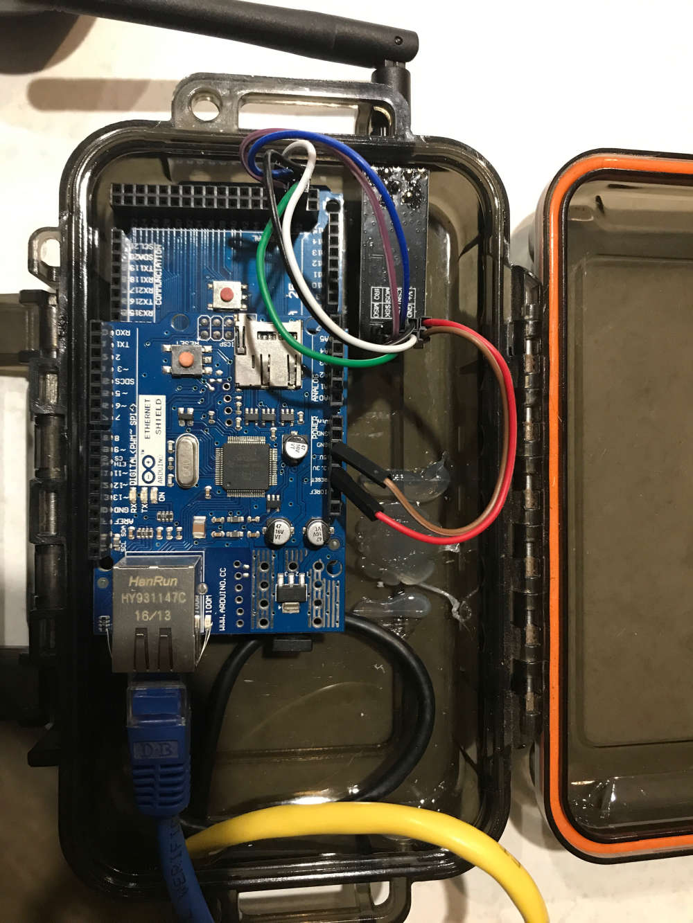
      I've completely rebuilt my gatewayNode from the ground up, and included the current sketch below.

      When I run the serial monitor on the bench, i get a slow "eth failed" message, which I expect (sadly I don't have Ethernet connection at my outdoor workspace) and when I plug it into the router (both USB to power the unit and eth) I get an "eth failed" message approx 4 times a second, but I can PING the address.

      I can't add the gateway to MyController, it just times out.

      I am powering the radio directly from the 3v pin on the mega, (no cap as I don't have any here) and there is nothing other than the LED indicators plugged into it.

      I'm just trying to work out where I should START looking, before i go back to pulling my hair out!

      Any advice greatly appreciated!

      /**
       * NRF24/Ethernet Gateway Node - v0.1
       */
      
      // Enable debug prints to serial monitor
      #define MY_DEBUG
      
      // Pin Confuguration for Arduino Mega
      #define MY_RF24_CE_PIN 49
      #define MY_RF24_CS_PIN 53
      
      // Radio type
      #define MY_RADIO_NRF24
      
      // Ethernet module type
      #define MY_GATEWAY_W5100
      
      // MAC Address
      #define MY_MAC_ADDRESS 0xDE, 0xAD, 0xBE, 0xEF, 0xFE, 0xED
      
      // Enable MY_IP_ADDRESS here if you want a static ip address (no DHCP)
      #define MY_IP_ADDRESS 10,0,0,201
      #define MY_IP_GATEWAY_ADDRESS 10,0,0,1 
      #define MY_IP_SUBNET_ADDRESS 255,255,255,0
      
      // Listening Port
      #define MY_PORT 5003
      
      // MyController IP Address
      #define MY_CONTROLLER_IP_ADDRESS 10,0,0,200
      
      // Enable inclusion mode
      #define MY_INCLUSION_MODE_FEATURE
      // Enable Inclusion mode button on gateway
      //#define MY_INCLUSION_BUTTON_FEATURE
      // Set inclusion mode duration (in seconds)
      #define MY_INCLUSION_MODE_DURATION 60
      // Digital pin used for inclusion mode button
      //#define MY_INCLUSION_MODE_BUTTON_PIN  3
      
      // Set blinking period
      #define MY_DEFAULT_LED_BLINK_PERIOD 300
      
      // Flash leds on rx/tx/err
      #define MY_DEFAULT_ERR_LED_PIN 22  // Error led pin
      #define MY_DEFAULT_RX_LED_PIN  26  // Receive led pin
      #define MY_DEFAULT_TX_LED_PIN  24  // Transmit led pin
      
      #include <Ethernet.h>
      #include <MySensors.h>
      
      void setup()
      {
      	// Setup locally attached sensors
      }
      
      void presentation()
      {
      	// Present locally attached sensors here
      }
      
      void loop()
      {
      	// Send locally attached sensors data here
      }
      
      posted in Troubleshooting
      ZachFlem
      ZachFlem
    • RE: Gateway with Relays (4) on WEMOS D1 R1

      @bjacobse I liked the look of espEasy, but I had a lot of trouble getting it to connect to my wifi after adding my network settings. (I had to download the latest dev build) I'll have a go at the code you linked though, as I kinda like the idea of keeping mycontroller, and the relay actuator example looks too simple to be true!

      posted in Hardware
      ZachFlem
      ZachFlem
    • RE: Gateway with Relays (4) on WEMOS D1 R1

      @theol I've changed my setup that many times, i don't even know what it looks like anymore!

      I've ordered some radios and am going to try setting the mega up as a radio node and see if that works, otherwise I think it's time to buy an off the shelf controller...

      posted in Hardware
      ZachFlem
      ZachFlem
    • RE: Gateway with Relays (4) on WEMOS D1 R1

      @mfalkvidd I've just ordered the radios from ebay and this will be my final attempt to get this working! I was trying to avoid using any 2.4ghz radios as that band is already heavily congested around my home.

      posted in Hardware
      ZachFlem
      ZachFlem
    • Gateway with Relays (4) on WEMOS D1 R1

      Hi folks,

      I'm having trouble getting this hunk of junk working, and I'm about ready to go out and buy a commercial controller because I've invested way too much time and effort into this already.

      I have had my irrigation controller working on a mega/uno with a w5100 ethernet shield, and thats all good except I have no wired network available where the unit is located, so I wanted to move to a wifi enabled platform.

      I've tried with a sparkfun esp8266 shield, but that's not compatible with MySensors, so I bought a wemos D1 (R1) and while I can get it to connect to the network and make it available in MyController (static IP only) i can not get my relays to switch on/off.

      I've tried using the alternate GPIO numbers (which doesn't help me as they aren't consecutive as required by the relay example, and I'm not sure how I'd setup multiple relays)

      I'm hoping someone can offer me some advice that might help me get this Wemos D1 working with AT LEAST 2 relays, but ideally 4.

      Cheers

      Zach (The Frustrated Aussie Guy)

      posted in Hardware
      ZachFlem
      ZachFlem
    • RE: Sparkfun8266 Wifi Shield + Arduino Due = WiFi Gateway

      @yveaux well that's just not going to work for me, I'm trying to cut down on the amount of power supplies and random junk I have spread all over the place.

      posted in Troubleshooting
      ZachFlem
      ZachFlem
    • RE: Sparkfun8266 Wifi Shield + Arduino Due = WiFi Gateway

      @yveaux Well that's just handy isnt it! So that shield was a waste of $12 bux!

      I've just ordered a prototyping shield and I'm going to have a go at building my own hack job esp-01 based shield.

      I've got an existing MEGA that I want to retrofit with wifi, rather than rebuilding the whole thing from scratch, and I'm using a LOT of I/O, which I havn't seen much of on the ESP stuff.

      Unless you can suggest an ESP based MEGA replacement with plenty (20+) I/O pins available??

      Cheers

      posted in Troubleshooting
      ZachFlem
      ZachFlem
    • Sparkfun8266 Wifi Shield + Arduino Due = WiFi Gateway

      Hi Folks,
      I'm trying to convert an existing Ethernet Gateway (shield based w5100) into a WiFi gateway.

      I have the wifi shield working, can ping the Due etc.

      I've copied my relay code below the 8266 setup stuff, but I get an error when compiling:

      C:\Users\zach\Documents\Arduino\libraries\MySensors/MySensors.h:389:2: error: #error No forward link or gateway feature activated. This means nowhere to send messages! Pretty pointless.
      

      I guess it's because I have no:

      // Enable gateway ethernet module type
      #define MY_GATEWAY_W5100
      

      defined in my new sketch, but I'm not sure what to define. Will the w5100 work once the WiFi is up and running?

      I appreciate any help you folks can shed on this!

      Full sketch here:

      // Set the gateway type
      #define MY_GATEWAY_w5100
      
      // The port to keep open on node server mode
      #define MY_PORT 5003
      
      // How many clients should be able to connect to this gateway (default 1)
      #define MY_GATEWAY_MAX_CLIENTS 2
      
      
      #include <SoftwareSerial.h>
      #include <SparkFunESP8266WiFi.h>
      #include <MySensors.h>
      
      // Define relays
      #define RELAY_1  2            // Arduino Digital I/O pin number for first relay (second on pin+1 etc)
      #define NUMBER_OF_RELAYS 4    // Total number of attached relays
      #define RELAY_ON 0            // GPIO value to write to turn on attached relay
      #define RELAY_OFF 1           // GPIO value to write to turn off attached relay
      
      // Replace these two character strings with the name and
      // password of your WiFi network.
      const char mySSID[] = "yourSSIDhere";
      const char myPSK[] = "yourPWDhere";
      
      void before()
      {
        for (int sensor = 1, pin = RELAY_1; sensor <= NUMBER_OF_RELAYS; sensor++, pin++) {
          // Then set relay pins in output mode
          pinMode(pin, OUTPUT);
          // Set relay to last known state (using eeprom storage)
          digitalWrite(pin, loadState(sensor) ? RELAY_ON : RELAY_OFF);
        }
      }
      
      void setup()
      {
      
      }
      
      void presentation()
      {
        // Send the sketch version information to the gateway and Controller
        sendSketchInfo("Audry - GW w/Relays", "1.0");
        
        for (int sensor = 1, pin = RELAY_1; sensor <= NUMBER_OF_RELAYS; sensor++, pin++) {
          // Register all sensors to gw (they will be created as child devices)
          present(sensor, S_BINARY);
        }
      }
      
      
      void loop()
      {
      
      }
      
      void receive(const MyMessage &message)
      {
        // We only expect one type of message from controller. But we better check anyway.
        if (message.type == V_STATUS) {
          // Change relay state
          digitalWrite(message.sensor - 1 + RELAY_1, message.getBool() ? RELAY_ON : RELAY_OFF);
          // Store state in eeprom
          saveState(message.sensor, message.getBool());
          // Write some debug info
          Serial.print("Incoming change for sensor:");
          Serial.print(message.sensor);
          Serial.print(", New status: ");
          Serial.println(message.getBool());
        }
      }
      
      posted in Troubleshooting
      ZachFlem
      ZachFlem
    • RE: NOT WORKING: DHT and RELAYS on Ethernet GW

      @rejoe2 said in NOT WORKING: DHT and RELAYS on Ethernet GW:

      @zachflem said in NOT WORKING: DHT and RELAYS on Ethernet GW:

      any thoughts?

      Not sure about if that's still valid, but there had been the recommendation to use ChildID 1 for the first relay. So you may use 3+4 for temp/hum or start with 10, 20 (or whatever you like) as proposed to have room for further relays or other type of switches.

      Yeah, just re-read it and found the hard define for the IDs of those, and set them to 100 and 101.

      Now I have the 2 relays defined as 1 & 2 and the Humidity as 100 and Temp as 101.

      Can see all 4 sensors but only getting a value from the temp sensor.

      posted in Development
      ZachFlem
      ZachFlem
    • RE: NOT WORKING: DHT and RELAYS on Ethernet GW

      @gohan said in NOT WORKING: DHT and RELAYS on Ethernet GW:

      What kind of gateway are you running?

      An arduino mega clone with a w5100 based ethernet shield.

      I think I might have found the problem, the humidity sensor reports as ID 0, the 2 relays as 1 and 2, and the temp sensor is showing up as 1, but before the relay.

      So I think i need to add something to the sketch so that each type of sensor has a different prefix.

      i.e. relays are 1XX, temp are 2XX etc

      any thoughts?

      posted in Development
      ZachFlem
      ZachFlem
    • RE: NOT WORKING: DHT and RELAYS on Ethernet GW

      @gohan said in NOT WORKING: DHT and RELAYS on Ethernet GW:

      DHT sensors are quite lazy so they need their time, try adding a wait(1000) before the

      float temperature = dht.getTemperature();

      So far I've done this, and I have a value coming from the GW for humidity, and I'm seeing a presentation for the temp sensor in the logs, but nothing comes up when I discover the GW...

      posted in Development
      ZachFlem
      ZachFlem
    • RE: NOT WORKING: DHT and RELAYS on Ethernet GW

      So I've moved inside (it was bloody hot in the shed) and I'm working on my development board (it's a mirror of the setup in the shed, minus the external power supply for the sensors)

      But with the shed sketch loaded into this MEGA, I'm getting the DHT values in the Serial Monitor, I'll hook it up proper to the network and see how we go.

      posted in Development
      ZachFlem
      ZachFlem
    • RE: NOT WORKING: DHT and RELAYS on Ethernet GW

      @gohan nope, just checked, and I can see the presentation, and my manual trigger of the relays, but no data back from the sensor.

      I'm also only getting the humidity presented to MyController

      posted in Development
      ZachFlem
      ZachFlem
    • RE: NOT WORKING: DHT and RELAYS on Ethernet GW

      OK folks, so I've got it going to some extent.

      Added the wait(), and that seems to have calmed things down a bit, but I also added an external 5v power supply to the sensor and relay board

      The relays are working, and the temp and humidity are being reported on the serial monitor, but there is no value coming back to MyController from the DHT22.

      Sketch @ https://pastebin.com/mMxh65xp

      As always, your help is appreciated.

      Cheers

      posted in Development
      ZachFlem
      ZachFlem
    • RE: NOT WORKING: DHT and RELAYS on Ethernet GW

      @gohan would the 5 minute wait() affect the rest of the loop? as in, if I add the wait, will it delay the activation of relays etc

      posted in Development
      ZachFlem
      ZachFlem
    • NOT WORKING: DHT and RELAYS on Ethernet GW

      Hi Folks!

      I've recieved my DHT11/22s and finally resolved an issue I was having with an ethernet shield (replaced the DOA unit with another new one) and I sat down to have a play and try and get one of the DHTs working on my current relay gateway/node and I ran into a loop of "Failed reading temperature from DHT!" but I can't work out what it is I'm doing wrong.

      I have the DHT working on it's own, or I have the relays working on their own, but not both at the same time.

      It doesn't seem to be a pin conflict or anything there, it may be power related though as I was trying to use the 3.3v pint o power the DHT and the 5v pin to power the relays.

      I need to invest (read: pull apart a phone charger) in a better 5v power supply for my gateway.

      If you fine people could cast an eye over my sketch and suggest any changes, maybe where I've gone wrong, or even a more elegant way of doing the same thing, I'd be greatly appreciative.

      note: for some reason i couldn't paste with code tags, so I've dumped it at pastebin:

      https://pastebin.com/HQpPKdeF

      Cheers in advance!

      posted in Development
      ZachFlem
      ZachFlem
    • My Home Automation Journey

      Hi Folks!

      I'm just starting out on my journey, and I'm going to be floating around here, probably asking stupid questions and generally trying to get my head around the whole thing.

      So some details of my build:

      Controller: MyController
      Part of the reason for this choice was because I have a friend that is currently using this controller, and let's face it, sometimes it's nice to have someone to bounce ideas off and to try out different things on a known working system etc.

      I'm currently running this on an old laptop that I've built using the Ubuntu server image, and have the controller software running along side the usual SSH etc as well as a LAMP stack for hosting my family intranet. Most of the admin duties are handled by Webmin using the web based GUI.

      Gateway: Arduino Mega & W5100 Ethernet Shield
      Should be pretty self explanatory, but I opted for the mega due to the extra IO available on it. And using cheaper Chinese clones, the price is down to around $15 per gateway.
      I'm not using wireless nodes, and my house isn't huge so should only require 2 gateways inside, along with another outside in the shed (there is an existing wireless bridge to the shed that it sits on)

      Topology: Multiple Star Wired
      Due to the size and layout of my house, I've opted (but not locked myself into) a dual zone star wired topology. One end of the house has the living area and kitchen. The other end has the bathroom and bedrooms etc.

      So Far...

      This whole project came about because of 2 things.

      1. I wanted a better way of controlling my watering system.

        This was the first step, as it was the least intrusive way to start playing around. I only want to control the sprinklers in my front and back lawn, so 2 zones. So I've got the ethernet gateway running in the shed with a 2 ch relay board hooked up and everything is going great.

      2. Light and Fan control in the toilet

        The price of conventional switches to control the off delay on the fan in my toilet was more than I wanted to pay. So I started to look at other options, and ended up here. I'm currently going through a process of converting all the lighting in my house to low wattage LED down lights that are connected to a standard plug-in base, the aim is to create an intermediate connection, using standard AUSTRALIAN 3 pin plugs and sockets.

      My Plans

      I've had some temp/humidity sensors delivered, so I'm going to have a play with those, and I'm going to have a look at eventually controlling my air conditioning.

      Look forward to updating you with more progress soon.

      posted in My Project
      ZachFlem
      ZachFlem
    • RE: Detect change of state on input

      @zboblamont said in Detect change of state on input:

      @zachflem Perhaps you are misunderstanding @pjr response. Usually the node is sleeping until a changed state wakens it, via interrupts is the way to do so normally.
      Although you can detect the change of state on any pin with the node running full time and polling the pin this is not energy efficient if it only has something to do on a state change, and fatal if it running on batteries. Viz - Running 8 hours continuously between the time you switched the light off at night, until morning when you turn the light on?

      No batteries here, it's a star wired setup that I'm trying to achieve. And there will be more switches than interupt enabled pins on the MEGA(s)

      posted in Hardware
      ZachFlem
      ZachFlem
    • RE: Anyone help with 4 relays please?

      @skywatch said in Anyone help with 4 relays please?:

      If anyone is interested this now works perfectly with mycontroller, local buttons and remote buttons too.....

      Any modification to the above code? This could be very handy for me!

      EDIT: does each button pin correspond to a relay? So in your example A0 relates to 4?

      Or can I use the rules in MC to dynamically assign buttons to operations?

      posted in Troubleshooting
      ZachFlem
      ZachFlem
    • RE: Detect change of state on input

      @pjr I don't think so. I have a simple switch that is either on or off, so the input will see either ground/5v or nothing, all i need to do is detect when that state changes and update the switchState variable to suit the opposite of it's current value (ON to OFF or vice versa)

      I haven't had a chance to play with it yet, but I think I can get that part working on the Mega without too much trouble, it will just be getting the MySensors node sending that data to MyController.

      I'm very green at all of this 😃

      posted in Hardware
      ZachFlem
      ZachFlem
    • Detect change of state on input

      Hi Folks,
      I've been lurking around, searching, trying to find some info on detecting change of state and using that to trigger my MyController rules.

      I have a steel framed house, and it's a nightmare to run new wiring in the walls, so I was hoping to utilise the existing light switches and detect the change of state (from OPEN to GROUND) on the MEGA.

      If any of you fine people have done this or something similar, I'd love to hear from you, or if anyone knows of some further reading, I'd appreciate if you could point me in the right direction.

      Cheers

      Z

      posted in Hardware
      ZachFlem
      ZachFlem
    • MyController (Ubuntu) + Ethernet Gateway + Relay Board

      Hi folks,

      I'm trying to get MyController to see my Ethernet Gateway and the 4xRelay board that's connected to it.

      I can use the relay board with a simple webserver sketch, seperate to mycontroller, so I can only assume that the wiring is correct.

      I can ping the MySensors(2.1.1) Gateway from my laptop and from the ubuntu server.

      I can add the Gatewat to MyController and it shows status as "Connected Successfully" and a nice green tick.

      And this is where I get stuck.

      Either I am not doing something correctly, or for some reason, my relay board isn't showing up/available.

      I am currently using sketches with as little modification as possible, gleaned directly from tutorials etc.

      Any advice greatly appreciated.

      TIA

      Zach

      Sketch Here:

      // Enable debug prints to serial monitor
      #define MY_DEBUG 
      
      // Enable gateway ethernet module type 
      #define MY_GATEWAY_W5100 
      
      // IP Connection
      #define MY_IP_ADDRESS 10,0,0,201                              // If this is disabled, DHCP is used to retrieve address
      #define MY_PORT 5003                                          // The port to keep open on node server mode / or port to contact in client mode
      #define MY_MAC_ADDRESS 0xDE, 0xAD, 0xBE, 0xEF, 0xFE, 0xED     // MAC Address, can be anything, but must be unique on the network
      
      // Include the various Libraries
      #include <SPI.h>
      #include <Ethernet.h>
      #include <MySensors.h>
      
      // Define relays
      #define RELAY_1  6            // Arduino Digital I/O pin number for first relay (second on pin+1 etc)
      #define NUMBER_OF_RELAYS 4    // Total number of attached relays
      #define RELAY_ON 1            // GPIO value to write to turn on attached relay
      #define RELAY_OFF 0           // GPIO value to write to turn off attached relay
      
      
      void before() { 
        for (int sensor=1, pin=RELAY_1; sensor<=NUMBER_OF_RELAYS;sensor++, pin++) {
          // Then set relay pins in output mode
          pinMode(pin, OUTPUT);   
          // Set relay to last known state (using eeprom storage) 
          digitalWrite(pin, loadState(sensor)?RELAY_ON:RELAY_OFF);
        }
      }
      void setup()
      {
      }
      
      void presentation()  
      {   
        // Send the sketch version information to the gateway and Controller
        sendSketchInfo("Audry - Gateway w/Relays", "0.1");
      
        for (int sensor=1, pin=RELAY_1; sensor<=NUMBER_OF_RELAYS;sensor++, pin++) {
          // Register all sensors to gw (they will be created as child devices)
          present(sensor, S_LIGHT);
        }
      }
      
      void receive(const MyMessage &message) {
        // We only expect one type of message from controller. But we better check anyway.
        if (message.type==V_LIGHT) {
           // Change relay state
           digitalWrite(message.sensor-1+RELAY_1, message.getBool()?RELAY_ON:RELAY_OFF);
           // Store state in eeprom
           saveState(message.sensor, message.getBool());
           // Write some debug info
           Serial.print("Incoming change for sensor:");
           Serial.print(message.sensor);
           Serial.print(", New status: ");
           Serial.println(message.getBool());
         } 
      }
      
      void loop() {
      }
      
      posted in MyController.org
      ZachFlem
      ZachFlem