Navigation

    • Register
    • Login
    • OpenHardware.io
    • Categories
    • Recent
    • Tags
    • Popular
    1. Home
    2. Zeph
    3. Best
    • Profile
    • Following
    • Followers
    • Topics
    • Posts
    • Best
    • Groups

    Best posts made by Zeph

    • RE: Over the air (OTA) bootloading update tutorial?

      OK, here's some background, for some eventual Wiki article or such.

      So there are 4 main ways to get a program into the uC:

      1. In System Programming (ISP) - uses SPI pins + reset, can program entire flash as well as fuses. This is how we get bootloaders into protected section of Flash. (There are also parallel programmers, and sometimes even additional methods like DebugWire or JTAG).

      Using these methods is more cumbersome, so the Arduino folks chose to use "bootloaders" - a small program programmed (via ISP) into a protected section of on-chip Flash, and which can in turn communicate with the outside world and write (program) a compiled sketch into the rest of on-chip flash. The bootloaders are invoked by rebooting (or upon powerup) the uC.

      1. Serial bootloader using Arduino bootloader protocol (subset of Atmel's STK500 protocol). A program in a protected section of uC onboard flash that can write compiled sketches into the rest of flash. Optiboot is the name of a particular serial bootloader used in many ATMega328p Arduino derivatives. (Not always used in APM (Arduino Pro Micros) but can be).

      2. MysBootloader - similar to the serial bootloader, is a small program in a protected section of on-chip flash which can write compiled sketches into the rest of the flash, but it gets the data to write from special Over The Air (OTA) bootloader packets rather than via the serial port.

      3. DualOptiboot - this is another OTA bootloader, but the idea is that you write the new compiled sketch (in binary) into an external flash chip, and then only after you have received and validated the entire new binary do you reboot and let the bootloader copy from external flash to on-chip flash. Called DualOptiboot because it's derived from OptiBoot and still supports serial bootloading as well.

      With the bootloaders, once they begin to program the rest of flash, they wipe out the old compiled sketch - the chip can't in general boot into a sketch again until all of the new sketch has been successfully programmed. With a serial bootloader, this is usually pretty straightforward and reliable. But flashing a page at a time via an OTA bootloader like MysBootloader is a little more dicey in that it's easy to miss packets and leave the chip in a "broken" state - with no workable sketch, only the OTA bootloader. The DualOptiboot approach is perhaps in some ways a little safer, in that the current sketch in on-chip flash is not overwritten until there is a validated copy of the new code in an external flash; then copying from external to internal flash by DualOptiboot is again pretty reliable and fast. Also, if all else fails, you can still open up the node and user serial bootloading. However, DualOptiboot only works when you have an appropriate off-chip flash memory connected, which limits your hardware.

      I believe that at this time, MysBootloader only works with the nRF24L01+. It basically needs a subset of the nRF's library in the bootloader section (which grows the bootloader from 1/2 KiB to 2KiB I think). Porting it to use the RFM69 would involve using a subset of the RFM69 library in the bootloader, and had not yet been done when this was written.

      If OTA bootloading fails, you can try again (you may need to power cycle the node). You can reduce the distance between source and destination. You can open the node and fall back to normal serial bootloading (at least with DualOptiboot, maybe with future versions of MysBootloader). And of course there is the fallback of using ISP (assuming the PCB doesn't do something to the reset & SPI lines that breaks that option).

      Since MysBootloader keeps requesting replacements for missing or corrupted OTA bootloading packets, it usually won't fail unless the node is really out of range or there is terrible interference.

      Tekka points out below a different failure mode - suppose the bootloading was successful, but the sketch itself is faulty (bugs). A serial bootloader like OptiBoot takes control upon reset (which in modern Arduinos can usually be triggered via the serial connection using an additional wire), and goes into bootloading mode if it receives proper data on the serial port - or if not, starts the currently loaded sketch. This may also happen on power up. For an OTA bootloader there's no additional wire to trigger reset on the target uC. Tekka says that MysBootloader can recover and load another sketch OTA while for some bugs in a sketch, DualOptiboot cannot recover (without a manual reset).

      posted in General Discussion
      Zeph
      Zeph
    • Generalizing MySensors

      As best I understand it, MySensors was originally developed around the conceptual framing of devices as used by Vera/MiCasaVerde/MIOS; has been remapped by some adapters to work with other systems; and is at the stage where the semantic gaps are becoming obvious enough to raise the question of rethinking the internal conceptual framework to be more general and less Vera specific.

      Let's start from the bottom of the hierarchy - what we could call "variables" - each containing a value which may vary over time.

      **Format: **
      The values could be

      • floating point or integer (of various sizes), or
      • chosen from an enumerated set of possible values (a common case being binary options like on/off or true/false or armed/unarmed etc)
      • a text string

      What it measures (or controls):
      In the case of a numeric value, this could be temperature or relative humidity or wind speed or water depth or brightness or rate of flow of electricity or water or accumulated flow of electricity or water or loudness of sound, or angle of a servo, etc. Sometimes there may be no conventional dimension or interpretation.

      Units and scaling
      There may be a translation to a standard unit of measure like degrees C or F, or percent humidity, or feet or meters, or mph or kph or m/s, or lux, or db or angular degrees or radians, etc. Sometimes we may know the dimension being measured (brightness) but have no translation to standard units (not calibrated in lux, just an arbitrary and perhaps non-linear value) so this is optional. And sometimes there may be a scaling factor needed to get to some standard unit, from the value reported.

      The dimension and the units are often conflated, but of course a value in degrees C could be a temperature reading or a dewpoint, two different dimensions which use the same units.


      That's the basic level - a set of distributed variables measured from the real world (or computed from measurements), or controlling some action in the real world. Then we built on top of that.

      Grouping of related measurements
      We might wish to associate several variables with a given device or sensor. For example a weather station might have temp and humidity and wind speed and wind direction, etc. Or a flow meter might have immediate flow (gph or kw) as well as accumulated flow (gals or kwh).

      This is where some things go a little wonky, because there isn't always one obvious way to logically group variables, and there may be little guidance as to the best practicies OUTSIDE OF matching the way a particular controller has chosen to conceptually organize things.

      From the top down, MySensors groups sensactuator variables by the wireless node which reports or uses them. This has a lot of practical sense to it, but in some sense it's a transport or addressing concept rather than a sensor concept. Suppose you had some one wire sensors strung around the property. As you add, remove and move wireless nodes around over time, you might find it more convenient to connect the (relatively long) wiring to different wireless nodes for reporting to the controller. In this case, the actual one-wire sensor would not change in any logical way (it's still measuring the same thing in the same location) but the values are reported through a different path, a different wireless node. So grouping of values by wireless node should be done lightly - it's not a primary logical grouping based on what is being measured or controlled, but more of "the current address and transport path".

      The child id is also part of the addressing and transport path.

      From the bottom up, MySensors group sensactuator variables into Sensors, each of which has a sensor type. This is one of the confusing areas, since the types of sensors seems to overlap semantically with the types of variables which might be associated with it.

      In trying to sort through this, I think the Sensor type mostly represents "which user interface object in the Vera system should be used to display and accept user input" for a group of variables". So if you have one or more related sensor variables which can logically be associated with a given Vera UI object, you may use that sensor type. Or you can do some more work and add a new sensor type to Vera, and use that.

      The problem is - another controller may not choose the same set of UI objects. I think that "sensor type" may be better conceptualized not at the MySensors generalized node level, but as a mapping of the generalized sensor nodes into the Vera system.

      In this approach (which is being brainstormed, and is not fully figured out), the sensor node would not need to understand Sensor Type (tho it would understand Variable formats, dimensions, scaling, units and names). Instead the gateway to Vera would map variables into Vera related groupings, and the gateway to another controller would map the variables into the groupings which makes sense to that system.

      Suppose that one controller had a user interface element which displayed weather related information graphically, always using metric values. Another controller has a "temp and humidity" user interface object but no weather station, tho it does have a separate flow concept to which wind speed could be mapped; the second one allows the user to select metric or imperial units. The first controller might display wind direction in degrees clockwise from true north, the second might use NNW type notation.

      The same physical sensors and associated variables (at the node level) might be grouped into "sensor UI objects" differently in the two controllers. But the nodes shouldn't care whether wind speed is shown inside the same box with temperature (a "sensor" UI element) or in separate boxes, or even omitted from a controller which doesn't have a target for some measurement. They just report values for variables, and the gateways alone handle grouping variables into user interface elements as used by the controller they support.

      In this model, more than one controller could be used with the same sensor network, so long as they don't issue conflicting commands. The sensors might always report temperature in C, and each controller + gateway would translate if it so needs. The sensors might report wind direciton in degrees and each controller + gateway would translate to compass points if so needed. If one of the controllers doesn't have a way to display "microcontroller temperature" or "H Bridge back-emf" then it can omit that variable, without precluding another controller from accepting such variables.

      Knowledge about the controller and its concepts would be removed from the wireless node code, and concentrated in the gateway to that controller. Nodes just report (or accept) one or multiple sensacturator variables. The gateway could package up groups of sensactuator variables as needed for the specific type of controller it serves. Suppose a given controller had a "temp & humidity" object but no weather station object. As described above, you could map wind speed into some other controller element for now. But then when a weather station "sensor type" with additional variables is defined next year, the gateway could regroup sensor variables into that package, without any changes in the wireless nodes.


      Splitting the gateway and the hub

      The concept of a gateway may need to be separated from the concept of the wireless hub.

      The wireless hub understands how to communicate with the wireless nodes, up through the protocol level of transferring sensactuator variable values back and forth. Like the nodes, it doesn't need to know what controller(s) are attached or their concepts, it just moves values. It could use a different radio chip, or RS-422.

      The gateway function translates from this general format to a specific controller's needs. (Cloud storage could be another type of "controller", by the way). The gateway function doesn't have to worry about ack and routing tables for the nRF24L01+.

      There is a general API between the MySensors wireless hub code and the MySensors gateways. They can run on the same processor (or not, if there is a transport option for the API).

      When you add a new controller, you write a new gateway, but can use the same wireless hub code.

      And a message manager like a MQTT broker could be inserted between the wireless hub and one or more gateways.

      That's the architecture which appeals to me. If it has enough appeal to others, including and especially hek, then maybe that will be version 1.5 or 2.0 of MySensors.

      This is where I was generally heading before discovering MySensors (which is WAY ahead of me in terms of practical implementation).

      posted in Development
      Zeph
      Zeph
    • RE: MQTT Broker gateway

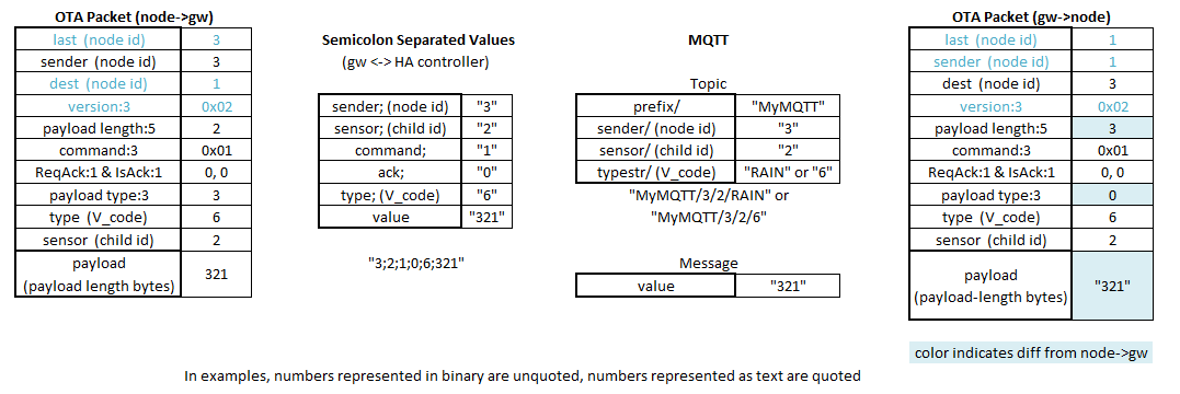
      As I understand it:

      MySensors_formats.gif

      The packet on the left would be from the node, the packet on the right would be to the node. Besides swapping sender and destination, the difference is that in 1.4 the gateway does not have the information to binary encode the value, so it sends the value as a string (payload type 0).
      EDIT: added alternate MQTT respresentation of V_code as numeric

      posted in Controllers
      Zeph
      Zeph
    • RE: New library to read Arduino VCC supply level without resistors for battery powered sensor nodes that do not use a voltage regulator but connect directly to the batteries ;-)

      I don't see how this technique saves any resistors or battery drain. I see there being two different measurements - input to a voltage regulator and input VCC to the uC, which are measured differently.

      By "this technique" I mean using VCC as the analog reference (as usual) and reading the internal 1.1V internal source. That gives you 1.1v as a fraction of VCC, so you can easily calculate VCC..

      The two measurements:

      1. You want to measure regulator INPUT voltage. You typically use a voltage divider to reduce the regulator INPUT voltage to less than VCC, which is used as the ADC reference. The technique describe here cannot be used for that measurement, so it doesn't save resistors or battery drain.

      2. You want to measure regulator OUTPUT voltage - or raw voltage if there is no regulator - as applied to the uC for VCC power. The technique described is the way to go, and a voltage divider is inappropriate.

      If you used a voltage divider on VCC (case 2) and measured it against the normal VCC reference, all you'd get is a fixed value determined by the resistors, not reflecting VCC.

      Summary: if (1) you want to measure regulator input, use a voltage divider, but if (2) you want to measure VCC then use this (well known) technique. Neither approach substitutes for the other. And you can use both, if you want both measurements (eg: if you are concerned about regulator drop-out).

      Side note. There are yet other approaches. You could use the 1.1v source as REFERENCE for the ADC instead of VCC, and on the ADC input use a voltage divider from VCC or from regulator input, with a large enough ratio to bring the measured voltage down to less than 1.1v. If you had a 5v processor fed via regulator from a 7.2v source, you could measure the former with a 4:1 resistor ratio and the latter with an 6:1 or greater ratio. This is not commonly done.

      If you DO use a voltage divider for measuring voltage (when appropriate), you can reduce the current wasted by using large resistors in the hundreds of Kohm range, AND putting a cap across the lower resistor. You need the cap to reduce the effective impedance into the ADC. If you just use large resistors, the internal capacitance of the ADC circuitry will be charged too slowly during measurement.

      posted in Development
      Zeph
      Zeph
    • We are mostly using fake nRF24L01+'s, but worse fakes are emerging.

      (see new links at end of this post)

      (see earlier thread about nRF24l01(no plus) substitutes - not quite the same topic as this thread but related; from a comment below)

      (see newer thread on finding the best nRF24L01+)

      First off, it appears that most of the cheap nRF's have been fakes (not genuine Nordic chips). There is some indication that they may use somewhat more power and be somewhat less sensitive, than the real thing - and may be more sensitive to power supplies. Not a big problem, since that level of performance is what we're used to (many of us have probably never used a Nordic nRF24L01+).

      However, there are even cheaper fakes hitting the market, with inferior specs and outright incompatibilities. In particular, the Si24R1 got the ACK bit inverted (following an error in the datasheet), so it's incompatible with the real nRF24L01+ (and good clones) in ESB mode. (The Si24R1 is often falsely labeled as nRF24L01+). In some cases you can build a network of such variants that work OK together, but a node with the other chip won't work right (at least in ESB mode). There are several other clones too, with whatever changes they happen to have.

      And clone chips weren't enough, there is a new cheap module with the chip under an epoxy blob (no biggee per se), which also omits a number of the passive components in the Nordic reference design used by most modules (caps, resistors, inductors). This seems to have problems with the ACK bit due to the chip itself (see avove), but due to module design also probably has reduced actual transmit power, less power filtering, etc. (And would even if it had a good chip in it).

      I'm mentioning this because chips that don't work right in some circumstances (depending on which features are used), or which are electrically marginal and thus have intermittent problems, can lead to serious hair loss. And this is probably going to be an increasing problem in our niche, as our vendors switch to the cheapest suppliers.

      If you are having odd problems, sometimes it may be that you have one of the clone chips or cost reduced modules.

      Perhaps we need to find a good supplier who knows we want only "genuine" high quality clones 🙂 and who will not suddenly switch to less compatible ones. In the DIY christmas lighting community many people patronize one particular Ali Express vendor (Ray Wu) who has an overall good reputation within that community, who is aware that many people in that community communicate frequently, and who wants to keep a good reputation. He gets enough volume from that community to have incentive to keep up his quality and to fix problems (at least in relative terms among Ali Express vendors).

      Some background:

      http://hackaday.com/2015/02/23/nordic-nrf24l01-real-vs-fake/

      http://ncrmnt.org/wp/2015/03/13/how-do-i-cost-optimize-nrf24l01/

      Updates:

      List of related chips (if not mislabeled as Nordic these would be clones, derivatives or compatibles, not fakes per se, but I'll list them here as some fakes may really be one of these chips or closer to it): http://sigrok.org/wiki/Protocol_decoder:Nrf24l01

      Info about Si24R01 and power: https://github.com/solarkennedy/equail/tree/master/Libraries/RF24

      posted in Hardware
      Zeph
      Zeph
    • RE: 💬 Serial Protocol - 2.x

      I've been gone for a while, but this seems like a nice next step. Feel free to move these comments to the forum if that make more sense. If it's too late for this round, perhaps they can be useful for the next revision.

      1. I still think the controller (or if need be, the gateway) should do any neccessary conversion between metric and imperial units, rather than pushing it down to every node; it seems like some kind of violation of partitioning to push that UI customization concept (which in many controllers the user can toggle freely or even display both ways) down to the node level, where it adds unneeded complication. But I'll let that go.

      2. It would be good to augment this with a systematic description of the underlying value type (int32, float32, string), and implied units if appropriate (potentially two units, for metric and imperial). For example, is wind speed in m/s or km/hr (assuming metric)? Is pressure in mmHg or hPA?

      3. Aside from the type and implied units, there are a few hints given already - what 0 and 1 mean, an enumerated list of valid string values, color given a strings of hex digits, position as a multivalued structured string, etc. Keep those as notes in augmented docs as described in #1, and add more a needed (eg: IR commands)
        2A) Is there any logic to when enumerated values are encoded as integers, and when they are encoded as strings from a controlled vocabulary? Could we get by with one or the other, rather than this hybrid?

      4. How do the semicolons internal to V_POSITION interact with the semicolons in the message field structure? If the same character is used for both, some note about that is needed. Or use commas in the former (substructured payloads) and semicolons in the former (overall message structure).

      5. I'm glad to see that a distinction has been made between sensed light levels in Lux and uncalibrated light levels. Generalizing, I can see four types of possible reporting of such things. 1: uncalibrated results in arbitrary units (eg: ADC values of a LDR+resitor voltage divider), 2: scaled results 0-100%, 3: reporting in predefined units understood by both sides, like Lux, 4: reporting in uninterpreted units which can only be displayed but are not parsed. In the first case, I think the only thing to define for a given V_variable is whether brighter should be reported as higher or lower. This standard chooses 0-100% for V_LIGHT_LEVEL. Could't that be reported as V_PERCENTAGE instead? That is, use V_PERCENTAGE for any sensor reporting in scaled percentages.

      6. If the protocol is going to allow for both uncalibrated and calibrated values (the latter in implied units), as with light levels, then I think it makes sense for the value with implied units to be the more specific variable; that is, V_LIGHT_LEVEL should be in lux, and V_LEVEL (or V_PERCENTAGE) would be used for the generic values, without units.

      5A) V_LEVEL currently seems a little convoluted. It appears that the implied units depend upon which S_sensor the variable is associated with, which kind of breaks the pattern that units (if any) are implied by V_variable. And for S_DUST, S_AIR_QUALITY) there are no units. So for a calibrated light level in lux OR an uncalibrated dust level, use V_LEVEL but for an uncalibrated light level use V_LIGHT_LEVEL. V_LEVEL seems to be a grab bag of conceptually unrelated magnitude values, some with per-S_sensor implied units and some without. This could use rethinking. How about if V_LEVEL was used for any values which do not have implicit units (see #1 above), and V_PERCENTAGE was used if the value scales to 0..100%. Other V_variables could have pre-specified implicit units (metric and imperial).
      5B) V_UNIT_PREFIX is really more of a suffix than a prefix. But this can work well with 5A above. If a value is reported as V_LEVEL then there are no interpreted or parsed units involved and the controller is not expected to be able to interpret or convert units. However, V_UNIT_SUFFIX could optionally supply a free text string with can be displayed after the value. So if you are reading a LDR and reporting the raw ADC value (or inverted value to ge the direction right), use only V_LEVEL. If you are reporting something in units not understood by the system, then use V_LEVEL and describe the units in V_UNIT_SUFFIX. (And if you are reporting percentage, use V_PERCENTAGE).

      1. Semantically, there are two kinds of outputs: set-current-value which sets a new state to be retained, and trigger/command which performs some action once. It's kind of like edges and levels in hardware logic. Setting the same value twice is harmless, but issuing the same command twice may have different effects than sending it once. Most of the outputs are about set-current-value. However, some are commands - like sending an IR code.
        6A) What do V_UP, V_DOWN, and V_STOP mean? Unless they contain payloads to configure a (retained) movement speed or something, they seem more like commands/triggers rather than set-current-value. In that case, it makes more sense to have a V_SHADES variable which is set to 0,1,2 for stop, up and down (which are mutually exclusive), than to have three variables which could be set in parallel. Likewise with V_SCENE_ON and _OFF. These should be handled with one V_variable, much as sending a IR command. This is also easier to extend for an additional command to the same device - just define additional values to action associations, rather than needing to add a new V_variable.
        6B) (A shade controller which could set/report percentage opening could use V_PERCENTAGE)

      2. Likewise there are two kinds of inputs: report-current-value and trigger-event. Mostly this protocol is about report-values. However the trigger functionality comes up in terms of V_TRIPPED, which is often implemented as a trigger. It should be made explicit what resets a triggered state: some systems use autoreset where after one report a device goes back to untriggered (trigger/event); other systems will keep reporting triggered forever until separately reset by some other means (report-current-state). We should be clear which mode this protocol expects.

      It's good to see the ongoing refinement of MySensors and related initiatives! These are definitely meant to be helpful, not as criticism! Your work is much appreciated.

      posted in Announcements
      Zeph
      Zeph
    • RE: Introducing MySensors on nRF24LE1

      Great work indeed!

      However, the source link (at this time) fails...

      posted in My Project
      Zeph
      Zeph
    • RE: Transformers

      @jendrush said:

      Maybe small usb wall charger for 1,4$, and regulator from 5V to 3.3V for 0,1$ would be good solution?

      For some projects, using cheap chargers can be a good option. However, I'd open any such cheap charger and have a look before using it. Some appear to be acceptably designed, and some appear to be dangerous designs, from the teardowns. For example:

      http://www.righto.com/2012/10/a-dozen-usb-chargers-in-lab-apple-is.html

      He rated 2 out of the batch as downright dangerous.

      Even with one which appears to have a reasonable design with enough separation, I would not be poking around in the sensors or PCB while they are currently powered from 230V with a cheap charger. Unplug first. And if you need power for programming or testing, use your normal USB supply (eg: a laptop or a high quality power supply) or batteries. Maybe that's just me, but this seems like a reasonably easy additional precaution. Even if the PCB has good separation, the insulation between windings of a transformer could be marginal, for example.

      Most readers here probably already know this, just thought it was worth noting for anybody coming to this hobby more recently.

      posted in Hardware
      Zeph
      Zeph
    • RE: 2.0 Discussion: Units, sensor types and protocol

      @hek said:

      Yes, and to extend this even further it would be great to be able to distribute/push simple rules all the way out to the nodes. It might be enough with simple scheduler-commands to start with but this could easily support even advances scenarios. The question is where to set the cuttingpoint...

      For the level of protocol under current discussion, the cuttingpoint could just be giving nodes an optional sense of time (using broadcast packets to keep in sync with the master as needed). And making use of that time as part of the (optional) accumulation enhancement for some variables.

      What else they do with that time at higher layers would continue to evolve in the future. We don't have to bite it all off now.

      posted in Announcements
      Zeph
      Zeph
    • RE: New library to read Arduino VCC supply level without resistors for battery powered sensor nodes that do not use a voltage regulator but connect directly to the batteries ;-)

      @Yveaux said:

      Off-topic: why the heck did @hek add support for this temperature sensor to mysensors 1.4 library??? IMHO It doesn't belong there at all!

      I think the internal ATMega temperature can be useful in some circumstances.

      Obviously if your goal is to measure weather, there are much better external sensors. But if your sensor is primarily detecting motion or open doors or controlling relays whatever, you may not always have an external temperature sensor included - but you always have a internal one, for free - albeit low accuracy.

      Or if you do have an external temperature sensor, the internal temp could be used as a sanity check - if in your physical setup the processor should be close to the same temperature as the external sensor, but the two are way off, something needs to be checked. A bit of monitoring both could tell you the normal range of divergence. Again, this is free - no extra board space or cost.

      Another use case is processor monitoring, The internal sensor is actually better at telling you the die temperature, if there's any chance of it overheating (whether or not there is an external sensor), If the board is sealed, just how hot does it get inside the box? If you are putting out a lot of current on a lot of outputs, is the processor heating up? (For weather you'd have the external sensor outside the box and wouldn't know the inside temp).

      Yeah, it can be optional, but but the internal temperature is not worthless.

      posted in Development
      Zeph
      Zeph
    • RE: RFM73 experience

      Thanks ToSa.

      If anybody else plays with the RFM73, please see if it can use channels above 83, as the nRF24L01+ does.

      Like the nRF24L01 can use 2 byte addresses tho it's not documented (probably because there are too many false hits). Not documenting channels above 83 would be for different reasons.

      posted in Hardware
      Zeph
      Zeph
    • RE: 2.0 Discussion: Units, sensor types and protocol

      If there is interest in using somewhat of a standard rather than rolling our own (and I think a case could be made either way), it would be worth reviewing the IoTDB effort which is also trying to describe the semantics of sensor/actuator control. For example:

      https://iotdb.org/pub/iot-attribute.html

      posted in Announcements
      Zeph
      Zeph
    • RE: New library to read Arduino VCC supply level without resistors for battery powered sensor nodes that do not use a voltage regulator but connect directly to the batteries ;-)

      OK, now we are recapping the investigation JeeLabs did a year ago.

      I recommend these articles:
      http://jeelabs.org/2013/05/15/what-if-we-want-to-know-the-battery-state/
      http://jeelabs.org/2013/05/16/measuring-the-battery-without-draining-it/
      http://jeelabs.org/2013/05/17/zero-powe-battery-measurement/

      He did test the various circuits and values. The conclusion is that using a FET you can get the current drain even lower, but using 10 Mohm resistors and a cap he got the drain to sub-microamp.

      Once you get the drain down that low, the uC sleep current and battery self-discharge and capacitor leakage and any other sensors are going to dominate anyway. An open pin spec'd at +/- 1 uA, so even a sensor pin which you think is disabled may be drawing more current than that.

      Still, it can be fun to really go for the minimum possible.

      posted in Development
      Zeph
      Zeph
    • RE: Battery powering options

      The title is about batteries, but the subject of using cheap phone chargers has come up.

      Small note: Whenever I refer to "the regulator" below, I'm talking about the onboard regulator of the arduino variant you are using, not to any regulator chips inside the phone charger. Just to be very clear.

      Safety:
      If you ARE going to use cheap phone chargers, at least buy several and crack one open to look at the isolation on the PCB. (look at the pics on some web sites that have done this to get an idea what you are looking for) Then always unplug it before working on the sensor node - use an alternate high quality supply while programming and testing, Just In Case. And don't have any exposed conductors on your finished node, that could be touched.

      I would avoid the most compact ones with little room inside the case.

      And you might want to test the temperature of the charger under load before deciding to use a given model.

      Power quality.

      At least measure the output with a voltmeter, under the loads you use.

      If you try to run a 5V arduino (eg: APM = Arduino Pro Micro) from a 5V charger you could have problems (you must test). If you use Vin, you will likely have problems because there isn't enough voltage differential for regulation, a condition known as dropping out of regulation or drop-out. There are regulators with low drop out (LDO) specs that require less difference between input and output voltage, but those specs vary depending on the regulator and load. The ATMega chips have a lot of slack, so a 16 Mhz chip will probably still run fine if the output of the regulator is, say, 4.5v or maybe 4.0 volts so the voltage drop may not be critical. But the regulator may not be keeping the supply as stable when in drop-out - varying the voltage as load changes or passing through variations in the supply voltage (coming from a cheap charger).

      So you may be tempted to just feed the charger 5v into the arduino's VCC=5V pin. That may work, but (1) some regulators don't like having power applied to their output pin only, so check that it doesn't overheat or remove it, and (2) the regulation on cheap chargers can sometimes be very bad - either off-voltage or with a lot of ripple and noise. Some are better than others. Expect the cheap ones to usually get flakey in these regards well under their nominal supply (eg: a charger which says 1A might work well only up to half that). And they may be poor even at low current. If you have a scope you can look at it (being careful about isolation and safety).

      If you have a 3.3v arduino, you can probably feed the charger's 5v signal into its Vin and get a reasonably well regulated VCC=3.3v.

      WIth the above qualifiers, some cheap chargers work fine in the right situation.


      Of course, you should instead get a high quality power supply for each node. One problem is knowing that it is indeed a high quality supply - just paying more isn't a perfect predictor of that. Using a name brand may help, but there are plenty of reports of problems with name brand suppies too (tho we hope they are statistically less common). And a good supply may sometimes cost more than the node (3.3v APM = $3.50, nRF24L01+ = $1, dht-11 = $1, power supply = $10?)

      posted in Hardware
      Zeph
      Zeph
    • RE: Sensebender Micro

      @petoulachi said:

      BTW, what is the F() function ? instead of Serial.print("Sensebender Micro FW "); why using Serial.print(F("Sensebender Micro FW ")); ?

      It's a way to save some RAM. A simple string constant like "Hello" takes up 6 bytes of RAM and also 6 bytes of Flash (program) memory (6 bytes includes a single "hidden" byte of binary zero as an end-of-text marker). At startup and before your code executes, that bit of program memory is copied to RAM. The F() thing is a "macro" which causes the compiler save only the 6 bytes of Flash (no Ram used). The print function can (through C++ typing) fetch those 6 bytes from Flash at runtime for printing. If you have long or many text constants in your program, this can add up to some useful savings,when you only have 2K of RAM.

      See the "F() Macro" on this page: https://www.arduino.cc/en/Reference/PROGMEM

      posted in Announcements
      Zeph
      Zeph
    • RE: Generalizing MySensors

      @hek said:

      Grouping. I'm not fully convinced we can live without any grouping at all. Say for example we have two barometers attached to one node. They both report temperature, pressure and altitude. The reported variables need to be kept together in some kind of logical group not to mix values between sensors (one could be outside while the other is mounted on the inside of the house).

      One of the fundamental ideas in the original post is separating the controller's UI based semantic groupings from the sensactuator nodes, so that the code running in nodes is not Vera specific (nor specific to any other controller).. That way the sensor network could be controller agnostic, and translation to controller concepts would be done by the gateway to a given controller type (not yet sure if this is a plugin or driver, in your terms).

      What I hear from you is that there may also be some inherent semantic grouping of related sensactuator variables - not dependent on the controller and it's UI objects, but deriving from the physical world being sensed and controlled by the nodes. So if a sensor node were to have two DHT-22's (which can be separated by a fairly long cable), there would still be value in associating temp1 & hum1 as separate from temp2 & hum2.

      I have two tentative responses to that.

      • This inherent grouping might be handled by keeping the MySensors concept of a child id within a node.. Child 1 might have Temp and Humidity values, and child 2 might also have temp and Humidity values. That could still make sense. The thing to avoid is implementing controller-specific Sensor type at the node level.

      • The gateway to a given controller could be flexibly able to group arbitrary sensactuator variables into a given controller-specific object (with a controller-specific type). It might be common to associate sensactuator variables from the same child of the same node with a given controller object, but that need not be a limitation.

      One concept that might be useful is giving each child a network unique text name. The gateway configuration might refer to that child by name; this would be translated by the wireless hub into a node id and child id as transport concepts.

      posted in Development
      Zeph
      Zeph
    • RE: RFM69 wireless

      @kolaf said:

      I'm glad to see that someone else also finds that transceiver interesting

      I think a lot of us find it interesting (hence the Radiohead effort), and we will see how the support evolves over time. It's lower speed but longer range.

      What kind of range and speed are you getting currently, by the way?

      posted in Hardware
      Zeph
      Zeph
    • RE: Security

      I'm rethinking this thread a bit. A key problem that complicated our discussion was the short packet length. My goal was to add no more than 4 bytes to the packet contents, which implies some compromises.

      The new approach I'm considering is having an optional second packet with authentication & replay resistance resistance for the first packet.

      A given sensactuator node could be programmed to require this second packet or not, depending on what it controls. If it's required, then the node must receive both the command packet and the authentication packet (within some time period) before it would take actions.

      In this way, the regular packets could be unchanged and we would not need to reserve extra space.in the command packet. Meanwhile the authentication packet could have room for more information - eg: rolling code, nonce, hash of the payload of the other packet, as well as the plaintext normal routing headers.

      posted in General Discussion
      Zeph
      Zeph
    • RE: Soil Sensor analog values differ on Uno vs Pro Mini

      OK, the soil sensor is connected to a 3.3v regulated supply.

      But the Arduino sounds like it's still running at 5v, and by default the ADC reference is VCC. So at full scale soil sensor reading of 3.3v will be only about 2/3 of that 5v reference. (but 100% of a 3.3v reference).

      So they are both right, just using different ADC references.

      The 5V reference is probably fine, you lose a little bit of resolution (less than one bit) but soil moisture sensors are not exactly precise.

      If it mattered, you can connect the 3.3v supply to the Aref input and set the ADC to use Aref as it's reference, in which case you'll get the full resolution 0..1023 for 0..3.3v. In this case I probably wouldn't bother.

      posted in Troubleshooting
      Zeph
      Zeph
    • RE: Which are the *best* NRF24L01+ modules?

      Wow, what a mess to sort out.

      A given module may have

      • genuine Nordic nRF24L01+
      • genuine Nordic nRF24L01 (no ESB, no 250Kbps) - possibly marked as +
      • quality clone of either, possibly even out-performing Nordic in some way
        (some have higher RF power output)
      • clone with inverted OTA ack bit (ESB OK between same, incompatible with Nordic)
      • clone with reduced sensitivity and/or increased power usage
      • any of the above with missing passive components compared to Nordic reference design

      Meanwhile:

      • We cannot count on visual inspection (Nordic is fabless, some genuine chips may differ over time) or date codes.
      • We do not know of register tests to distinguish differences (except L01 vs L01+)
      • The inverted NoAck bit could be easily tested OTA using ESB mode to a known-good module.

      The packet loss testing may have value, but it can be tricky. NeverDie says " The modules seem more finicky about their orientation than others that I've tested, and moving things just a little can make for much, much worse results."

      That makes comparison difficult - is a given module better/worse than another, or was it it moved "just a little"? There's also the issue of intermittant interference in a crowded band.

      The idea of having "screwed down" test positions as someone suggested is making a lot of sense. Maybe.

      I'm wondering about the blobs that worked better than genuine/iTead nRF24L01+ (@1Mhz), is that because they are the higher powered clones? What's the power supply drain during transmit, compared to genuine?

      The RFM69 family is a good alternative for most sensors, where lower data rates and (regulatory) lower duty cycles of 433/868/915 MHz bands are usually OK. If we want the higher data rates of GFSK at 2.4GHz, maybe the RFM73 is more consistent (fewer if any clones)?

      posted in Hardware
      Zeph
      Zeph
    • RE: Raspberry Pi Zero $5

      It's hard to take the Raspberry Pi Zero seriously. It's now over three months since it first went on sale, and it's rarely in stock anywhere for more than hours; when you can find it, you usually have to buy it with some kind of overpriced "kit" for $30-60, with a limit of one. If you did get one and you were to fry it, or want to build a second device using it, it may take you months to find another one. They've sold over 3 million Raspberry Pi 2's, so they know how to ramp up production if the want to. All this makes the RPi Zero seem more of a gimmick for "bragging rights" to a nominal $5 computer, than a serious option for our purposes, unfortunately.

      posted in General Discussion
      Zeph
      Zeph
    • RE: Which are the *best* NRF24L01+ modules?

      @NeverDie
      http://tmrh20.github.io/RF24/classRF24.html#aa0a51923a09ba4f3478aba9be0f8a6a1

      You are going to need your Davy Jones uCurrent to measure sleeping current!

      posted in Hardware
      Zeph
      Zeph
    • RE: Raspberry Pi Zero $5

      @punter9 Thanks for the link, that gave some good background info, and some hope that those of us who are interested in playing with it will eventually be able to get one. (By pure chance, I happened to stumble across it minutes after it was first released, but didn't order one as I didn't have an immediate need, and I already have too many processors which I bought hoping to find a good use for already! Nevertheless I'll probably get one someday.)

      I wasn't commenting on the quality of the hardware, just on the suitability for our purposes; parts which are only available in quantity one every few months IF YOU ARE LUCKY have some limitations.

      From the article you linked, perhaps that will eventually change. We'll see. how soon. It's so cheap that if they don't keep limiting the quantities, one customer could buy up the full month's supply for embedding in a commercial product.

      I'm wondering how it would be useful to us in DIY home automation tho.

      As a node, I'm not seeing it as a major contender. Let's compare it to an Arduino Pro Mini (under $2 shipped). The minimal RPi zero plus memory, shipping and tax is going to be several times that.

      The RPi Zero as node takes a lot more power to run and will not power up and down so quickly and gracefully, so it's not going to work well with battery power (and will have a larger passive load on mains power). It tends to require a whole OS which often gets in the way of direct interfacing with hardware, and requires system administering. There aren't as many sensor libraries for it. It has a much faster CPU and far more memory, but for most nodes that's just overkill. I'm not seeing that it would be competitive for most nodes even at the same price as an APM. But there must be some special purpose home automation nodes where it would be useful - any ideas?

      Of course, it would work as server for some Home Automation Controller software. But you only need one of those, and how much money would it save once fitted out (relative to total system price) compared to using a RPi 3 (with built in WiFi and BLE) or RPi B+ @ $25, or BeagleBone Green?

      So I'm still wondering what niche it would fill, within our domain...

      What ideas do people have for making good use of a RPi Zero as a MySensors node, if it was easily available at the nominal price?

      (Understand, I'll probably eventually get one to play around with because it IS cool, but not necessarily for HA. I also have a $9 C.H.I.P. on order, and a $19 PINE A64, and a RedBear Duo, etc. But those are to feed my addiction, I don't see them as changing the DIY Home Automation landscape).

      posted in General Discussion
      Zeph
      Zeph
    • Raspberry Pi SD Card wear out?

      I was thinking to migrate to the Raspberry Pi (and try out various controller software).

      However, I am hearing about problems with wear on SD cards; apparently the cards can fail after too many writes. There is no TRIM control as with SSD's, so there is limited ability to wear-level. So there are reports of periodic SD failures with 24/7 software running on a RPi. That would not be ideal for a home controller!

      Has anybody had problems with this? Is some controller software better than others in this regard? (The problem can be reduced by using RAM disk (tmpfs) for highly volatile files).

      posted in Hardware
      Zeph
      Zeph