ENC28J60 Ethernet gateway
-
As I was having low reliability with my gateway, I'm trying to build an ethernet one. But I can't make it work. I have those components:
arduino nano
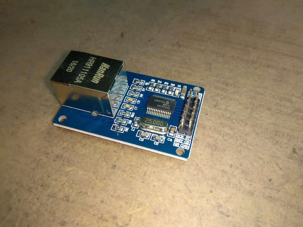
ENC28J60 nano ethernet shield (this one)
An original nrf24, shielded pa+lnaI'm burning this sketch, sligtly altered from examples:
#define MY_DEBUG // Enables and select radio type (if attached) #define MY_RADIO_RF24 //#define MY_RADIO_RFM69 //#define MY_RADIO_RFM95 #define MY_GATEWAY_MQTT_CLIENT // Set this node's subscribe and publish topic prefix #define MY_MQTT_PUBLISH_TOPIC_PREFIX "mys-in" #define MY_MQTT_SUBSCRIBE_TOPIC_PREFIX "mys-out" // Set MQTT client id #define MY_MQTT_CLIENT_ID "mys-langw-mqtt" // MQTT broker ip address or url. Define one or the other. //#define MY_CONTROLLER_URL_ADDRESS "m20.cloudmqtt.com" #define MY_CONTROLLER_IP_ADDRESS 192,168,50,201 // The MQTT broker port to to open #define MY_PORT 1883 // Enable these if your MQTT broker requires username/password //#define MY_MQTT_USER "username" //#define MY_MQTT_PASSWORD "password" #define MY_SOFTSPI //#define MY_SOFT_SPI_SCK_PIN 14 //#define MY_SOFT_SPI_MISO_PIN 16 //#define MY_SOFT_SPI_MOSI_PIN 15 // When ENC28J60 is connected we have to move CE/CSN pins for NRF radio #define MY_RF24_CE_PIN 5 #define MY_RF24_CS_PIN 6 // Enable gateway ethernet module type #define MY_GATEWAY_ENC28J60 // Enable MY_IP_ADDRESS here if you want a static ip address (no DHCP) #define MY_IP_ADDRESS 192,168,50,211 // If using static ip you can define Gateway and Subnet address as well #define MY_IP_GATEWAY_ADDRESS 192,168,50,1 #define MY_IP_SUBNET_ADDRESS 255,255,255,0 // The port to keep open on node server mode / or port to contact in client mode // #define MY_PORT 5003 // Controller ip address. Enables client mode (default is "server" mode). // Also enable this if MY_USE_UDP is used and you want sensor data sent somewhere. //#define MY_CONTROLLER_IP_ADDRESS 192, 168, 178, 254 // The MAC address can be anything you want but should be unique on your network. // Newer boards have a MAC address printed on the underside of the PCB, which you can (optionally) use. // Note that most of the Ardunio examples use "DEAD BEEF FEED" for the MAC address. #define MY_MAC_ADDRESS 0xDE, 0xAD, 0xBE, 0xEF, 0xFE, 0xED /* // Enable inclusion mode #define MY_INCLUSION_MODE_FEATURE // Enable Inclusion mode button on gateway //#define MY_INCLUSION_BUTTON_FEATURE // Set inclusion mode duration (in seconds) #define MY_INCLUSION_MODE_DURATION 60 // Digital pin used for inclusion mode button //#define MY_INCLUSION_MODE_BUTTON_PIN 3 // Flash leds on rx/tx/err #define MY_LEDS_BLINKING_FEATURE // Set blinking period #define MY_DEFAULT_LED_BLINK_PERIOD 300 // Flash leds on rx/tx/err // Uncomment to override default HW configurations //#define MY_DEFAULT_ERR_LED_PIN 16 // Error led pin //#define MY_DEFAULT_RX_LED_PIN 16 // Receive led pin //#define MY_DEFAULT_TX_LED_PIN 16 // the PCB, on board LED */ #include <Arduino.h> #include <SPI.h> #include <UIPEthernet.h> #include <MySensors.h> void setup() { // Setup locally attached sensors } void presentation() { // Present locally attached sensors here } void loop() { // Send locally attached sensors data here }- I copied the UPIEthernet v1.0.4 from the example.
But all I get in debug is:
18:25:24.979 -> 0 MCO:BGN:INIT GW,CP=RNNGA---,REL=255,VER=2.3.1
18:25:24.979 -> 4 TSM:INIT
18:25:24.979 -> 5 TSF:WUR:MS=0
18:25:24.979 -> 11 TSM:INIT:TSP OK
18:25:24.979 -> 13 TSM:INIT:GW MODE
18:25:24.979 -> 15 TSM:READY:ID=0,PAR=0,DIS=0
18:25:24.979 -> 17 MCO:REG:NOT NEEDED
I had to introduce the SoftSpi because I was getting radio init errors. But now, there's no traffic at all.
I've done everything possible, checked the wiring many times... Independly feeding the components...Does anyone use that setup? Thanks
EDIT: OK, so now I found that this module is not recommended.
-
So after being unable to make the nrf24 to work with the ENC28J60, I'm trying now something different. I started by making an rfm69 serial gateway with success. :clap:
Then I want to see if it could be possible to convert it to ethernet with the ENC28J60.
I searched and found everything in the forum. I arrived to the conclussion (that is probably wrong) that I must wire both radio and eth module using the same spi pins, activating a new driver and nothing more. But this doesn't work on the proto-board.There's something else to be done? Thanks.
-
@Sergio-Rius
unfortunaly I can't help with your enc28j60 issue. and I'm not sure to have one for testing this.A while back, we checked w5100 module + arduino 328p. Eth module and radio were working on same hw spi bus but in docs it uses softspi, I don't remember why, perhaps for having a dedicated spibus for ethernet..
I understand this is not very convenient to find the infos, when always more hw is supported.Just a note, as you are using a Nano for your tests, RFMs modules are not 5v tolerant in theory, even if they seem to handle it, datasheet says 3.9v for max. good to know. but maybe you're already using a level converter.
@scalz Thanks for your help. Unfortunately I can't get a w5100 in my country and would order it outside. I had those rfms for years and I want to test range before buying a sensebender.
And I'm convinced to stop using the wifi for a gw.I had hope that any used had the same hw already running.
-
@cabat Could you please share you pinout for radio and module, and the sketch configuration?
I can't make it work and I don't know if it's a matter of connections or something to activate, like softspi. -
@cabat Could you please share you pinout for radio and module, and the sketch configuration?
I can't make it work and I don't know if it's a matter of connections or something to activate, like softspi.@sergio-rius Pinout as described here Building an Ethernet Gateway, i am use module like this:
and my sketch on 20-Feb-2019 is:
#define MY_BAUD_RATE 9600 //#define MY_RF24_PA_LEVEL RF24_PA_MIN #undef MY_REGISTRATION_FEATURE #undef MY_CORE_COMPATIBILITY_CHECK // Enable debug prints to serial monitor #define MY_DEBUG // Enable and select radio type attached #define MY_RADIO_NRF24 //#define MY_RADIO_RFM69 // When ENC28J60 is connected we have to move CE/CSN pins for NRF radio #define MY_RF24_CE_PIN 5 #define MY_RF24_CS_PIN 6 // Enable gateway ethernet module type #define MY_GATEWAY_ENC28J60 // Gateway IP address #define MY_IP_ADDRESS 192,168,1,235 // The port to keep open on node server mode / or port to contact in client mode #define MY_PORT 5003 // Controller ip address. Enables client mode (default is "server" mode). // Also enable this if MY_USE_UDP is used and you want sensor data sent somewhere. //#define MY_CONTROLLER_IP_ADDRESS 192, 168, 178, 254 // The MAC address can be anything you want but should be unique on your network. // Newer boards have a MAC address printed on the underside of the PCB, which you can (optionally) use. // Note that most of the Ardunio examples use "DEAD BEEF FEED" for the MAC address. #define MY_MAC_ADDRESS 0xDE, 0xAD, 0xBE, 0xEF, 0xFE, 0xED // Flash leds on rx/tx/err //#define MY_LEDS_BLINKING_FEATURE // Set blinking period //#define MY_DEFAULT_LED_BLINK_PERIOD 300 // Enable inclusion mode //#define MY_INCLUSION_MODE_FEATURE // Enable Inclusion mode button on gateway //#define MY_INCLUSION_BUTTON_FEATURE // Set inclusion mode duration (in seconds) //#define MY_INCLUSION_MODE_DURATION 60 // Digital pin used for inclusion mode button //#define MY_INCLUSION_MODE_BUTTON_PIN 3 //#define MY_DEFAULT_ERR_LED_PIN 7 // Error led pin //#define MY_DEFAULT_RX_LED_PIN 8 // Receive led pin //#define MY_DEFAULT_TX_LED_PIN 9 // the PCB, on board LED #include <SPI.h> #include <UIPEthernet.h> #include <MySensors.h> void setup() { } void loop() { } -
@scalz said in ENC28J60 Ethernet gateway:
A while back, we checked w5100 module + arduino 328p. Eth module and radio were working on same hw spi bus but in docs it uses softspi, I don't remember why, perhaps for having a dedicated spibus for ethernet..
It may have been fixed by now, but originally the W5100 did not release the SPI bus properly. So, it needed a separate SPI bus from the radio.
I think this was fixed in the W5200 and W5500. -
@scalz said in ENC28J60 Ethernet gateway:
A while back, we checked w5100 module + arduino 328p. Eth module and radio were working on same hw spi bus but in docs it uses softspi, I don't remember why, perhaps for having a dedicated spibus for ethernet..
It may have been fixed by now, but originally the W5100 did not release the SPI bus properly. So, it needed a separate SPI bus from the radio.
I think this was fixed in the W5200 and W5500.@nagelc said in ENC28J60 Ethernet gateway:
I think this was fixed in the W5200 and W5500.
Noooooo..... Just ordered a W5100 :sob:
@cabat It may not do for me. I'm trying to use rfm69 now. I could not leave my existing network down and brought the nrfs back to where they belonged.
Also the eth module I have here is the shield for nano one. As it stacks below the nano, it may be that is interfering more pins than I expected.
What I would want to know is that the rfm69 needs a different pinout with this shield or not. I can't find any reference that tells me this, so I can start debugging the problem.
-
@nagelc said in ENC28J60 Ethernet gateway:
I think this was fixed in the W5200 and W5500.
Noooooo..... Just ordered a W5100 :sob:
@cabat It may not do for me. I'm trying to use rfm69 now. I could not leave my existing network down and brought the nrfs back to where they belonged.
Also the eth module I have here is the shield for nano one. As it stacks below the nano, it may be that is interfering more pins than I expected.
What I would want to know is that the rfm69 needs a different pinout with this shield or not. I can't find any reference that tells me this, so I can start debugging the problem.
-
@sergio-rius sorry, my mistake, missed of using RFM69 in your setup..
@cabat Oh, no! Thanks for your help. It has inspired me. Now I'm trying something more.
-
I've been fiddling with the radio alone (serial gw), softspi and changing pins, and I think there's something else here.
Well those are my findings:With this base definition and without the module wired:
#define MY_RADIO_RFM69
#define MY_RFM69_NEW_DRIVER
#define MY_IS_RFM69HW

#define MY_DEBUG_VERBOSE_RFM69

#define MY_GATEWAY_ENC28J60
It works as expected.
0 MCO:BGN:INIT GW,CP=RPNGA---,REL=255,VER=2.3.1
4 TSM:INIT
5 TSF:WUR:MS=0
6 RFM69:INIT
7 RFM69:INIT:PIN,CS=10,IQP=2,IQN=0
11 RFM69:PTX:LEVEL=5 dBm
13 TSM:INIT:TSP OK
15 TSM:INIT:GW MODE
16 TSM:READY:ID=0,PAR=0,DIS=0
19 MCO:REG:NOT NEEDED
72 GWT:TIN:IP=192.168.50.211
1075 MCO:BGN:STP
1077 MCO:BGN:INIT OK,TSP=1
1081 TSM:READY:NWD REQ
1083 RFM69:SWR:SEND,TO=255,SEQ=0,RETRY=0
1088 RFM69:CSMA:RSSI=-98
1090 TSF:MSG:SEND,0-0-255-255,s=255,c=3,t=20,pt=0,l=0,sg=0,ft=0,st=OK:
If I try to change CS pin to any other with
#define MY_RFM69_CS_PIN 4for example, I always get:0 MCO:BGN:INIT GW,CP=RPNGA---,REL=255,VER=2.3.1 4 TSM:INIT 5 TSF:WUR:MS=0 6 RFM69:INIT 7 RFM69:INIT:PIN,CS=4,IQP=2,IQN=0 11 RFM69:PTX:LEVEL=5 dBm 13 TSM:INIT:TSP OK 14 TSM:INIT:GW MODE 16 TSM:READY:ID=0,PAR=0,DIS=0 19 MCO:REG:NOT NEEDEDSo I revert the CS pin change and activate softspi and change irq
#define MY_SOFTSPIand#define MY_RFM69_IRQ_PIN 3And it works well:0 MCO:BGN:INIT GW,CP=RPNGA---,REL=255,VER=2.3.1 4 TSM:INIT 5 TSF:WUR:MS=0 6 RFM69:INIT 7 RFM69:INIT:PIN,CS=10,IQP=3,IQN=1 11 RFM69:PTX:LEVEL=5 dBm 13 TSM:INIT:TSP OK 15 TSM:INIT:GW MODE 16 TSM:READY:ID=0,PAR=0,DIS=0 19 MCO:REG:NOT NEEDED 72 GWT:TIN:IP=192.168.50.211 1075 MCO:BGN:STP 1077 MCO:BGN:INIT OK,TSP=1 1079 TSM:READY:NWD REQ 1081 RFM69:SWR:SEND,TO=255,SEQ=0,RETRY=0 1086 RFM69:CSMA:RSSI=-98 1091 TSF:MSG:SEND,0-0-255-255,s=255,c=3,t=20,pt=0,l=0,sg=0,ft=0,st=OK:Then I add the eth module and I get:
0 MCO:BGN:INIT GW,CP=RPNGA---,REL=255,VER=2.3.1
4 TSM:INIT
5 TSF:WUR:MS=0
6 RFM69:INIT
7 RFM69:INIT:PIN,CS=10,IQP=3,IQN=1
11 RFM69:PTX:LEVEL=5 dBm
13 TSM:INIT:TSP OK
15 TSM:INIT:GW MODE
16 TSM:READY:ID=0,PAR=0,DIS=0
19 MCO:REG:NOT NEEDED
And stays here forever.
Of course all those test are made using a double (5v+3v3) good power source, a level shifter... and changing the wires accordingly.
I have some questions:
- Its normal
MY_RFM69_CS_PINnot having effect and breaking the radion connection?
Without being able to change this, I don't know if it's spi interference. - In the last test, it seems to halt when initialising the network. Doesn't it?
Is there a way I can further know if the problem is with the eth module? I've tried it alone with the nano and it works.
I would thank guidance for debugging this.
- Its normal
Hello! It looks like you're interested in this conversation, but you don't have an account yet.
Getting fed up of having to scroll through the same posts each visit? When you register for an account, you'll always come back to exactly where you were before, and choose to be notified of new replies (either via email, or push notification). You'll also be able to save bookmarks and upvote posts to show your appreciation to other community members.
With your input, this post could be even better 💗
Register Login