ESP8266gateway with sensor
Hardware
2
Posts
2
Posters
91
Views
2
Watching
-
Hi,
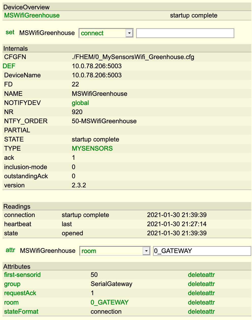
I would like to use the ESP8266gateway standalone with a sensor. I used the ESP8266gateway sketch and it connects without problems to my controller, but I can't get it to send a message to the controller (FHEM).
I made a very easy code, for testing. It would just be "light level" but in this case even without a sensor, just sending "100".
/*
  */

// Enable debug prints to serial monitor
#define MY_DEBUG

// Use a bit lower baudrate for serial prints on ESP8266 than default in MyConfig.h
#define MY_BAUD_RATE 9600

// Enables and select radio type (if attached)
//#define MY_RADIO_RF24
//#define MY_RADIO_RFM69
//#define MY_RADIO_RFM95

#define MY_GATEWAY_ESP8266

#define MY_WIFI_SSID "this is the SSID"
#define MY_WIFI_PASSWORD "And the password"

// Enable UDP communication
//#define MY_USE_UDP  // If using UDP you need to set MY_CONTROLLER_IP_ADDRESS or MY_CONTROLLER_URL_ADDRESS below

// Set the hostname for the WiFi Client. This is the hostname
// it will pass to the DHCP server if not static.
#define MY_HOSTNAME "ESP8266_Greenhouse"

// Enable MY_IP_ADDRESS here if you want a static ip address (no DHCP)
//#define MY_IP_ADDRESS 192,168,178,87

// If using static ip you can define Gateway and Subnet address as well
//#define MY_IP_GATEWAY_ADDRESS 192,168,178,1
//#define MY_IP_SUBNET_ADDRESS 255,255,255,0

// The port to keep open on node server mode
#define MY_PORT 5003

// How many clients should be able to connect to this gateway (default 1)
//#define MY_GATEWAY_MAX_CLIENTS 2

// Controller ip address. Enables client mode (default is "server" mode).
// Also enable this if MY_USE_UDP is used and you want sensor data sent somewhere.
//#define MY_CONTROLLER_IP_ADDRESS 10, 0, 78, 204
//#define MY_CONTROLLER_URL_ADDRESS "my.controller.org"

// Set blinking period
//#define MY_DEFAULT_LED_BLINK_PERIOD 300

// Flash leds on rx/tx/err
// Led pins used if blinking feature is enabled above
//#define MY_DEFAULT_ERR_LED_PIN 16  // Error led pin
//#define MY_DEFAULT_RX_LED_PIN  16  // Receive led pin
//#define MY_DEFAULT_TX_LED_PIN  16  // the PCB, on board LED

#include <MySensors.h>
#define CHILD_ID_LIGHT 0

MyMessage msgLight(CHILD_ID_LIGHT, V_LIGHT_LEVEL);

uint32_t WAIT_TIME = 1200; // Sleep time between reads (in milliseconds)


void setup()
{

}

void presentation()
{
  sendSketchInfo("GreenhouseWifiNode", "1.0");
  present(CHILD_ID_LIGHT, S_LIGHT_LEVEL);
}

void loop()
{
	//Light
  int16_t lightLevel = 100;
  Serial.println(lightLevel);
  send(msgLight.set(lightLevel));

  wait(WAIT_TIME);
}
This is the serial output:
connected with Eichenstrasse, channel 3
dhcp client start...
ip:10.0.78.206,mask:255.255.255.0,gw:10.0.78.1
5137 GWT:TIN:CONNECTING...
5165 GWT:TIN:IP: 10.0.78.206
5196 MCO:BGN:STP
5213 MCO:REG:NOT NEEDED
5238 MCO:BGN:INIT OK,TSP=NA
100
100
100
100
100
100
100
100
pm open,type:2 0
100
100
100
100
...
Any ideas what I do wrong?

-
Here is my code for doing something equivalent. You seem to have the pinMode line missing in setup()
// Initialize motion message
MyMessage msg(CHILD_ID, V_TRIPPED);

void setup() {
  pinMode(MOTION_SENSOR_PIN, INPUT_PULLUP);      // sets the motion sensor digital pin as input
}

void presentation() {
  // Present locally attached sensors here
  // Send the sketch version information to the gateway and Controller
  sendSketchInfo("Motion Sensor", "1.1");

  // Register all sensors to gw (they will be created as child devices)
  present(CHILD_ID, S_MOTION);
}

boolean pinstate = false;

void loop() {
  boolean newstate = (digitalRead(MOTION_SENSOR_PIN) == HIGH);
  if (newstate != pinstate) {
    if (newstate == true) {
      send(msg.set("1"));
      Serial.println("Motion Started");
      pinstate = newstate;
    } else {
      send(msg.set("0"));
      Serial.println("Motion Stopped");
      pinstate = newstate;
    }
  }
}
