
nRF24Doctor
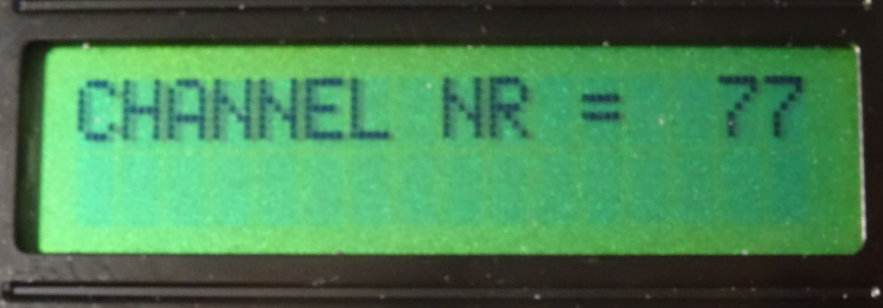
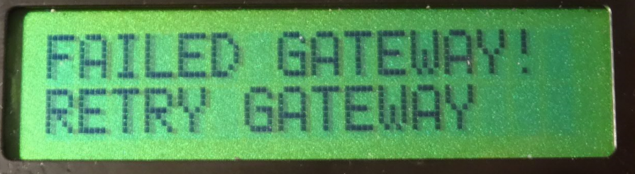
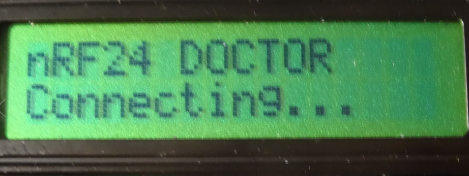
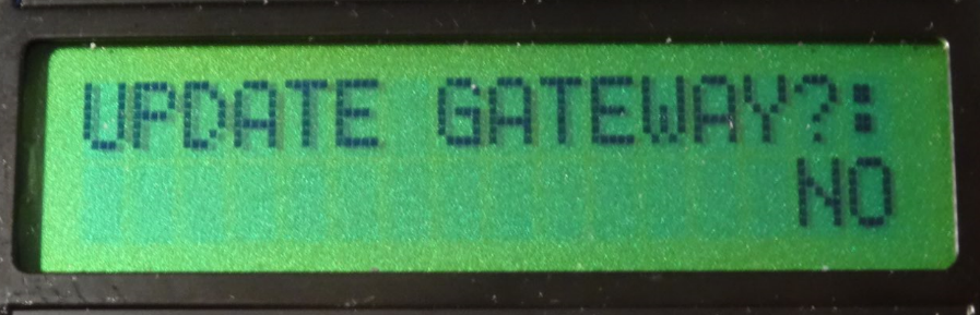
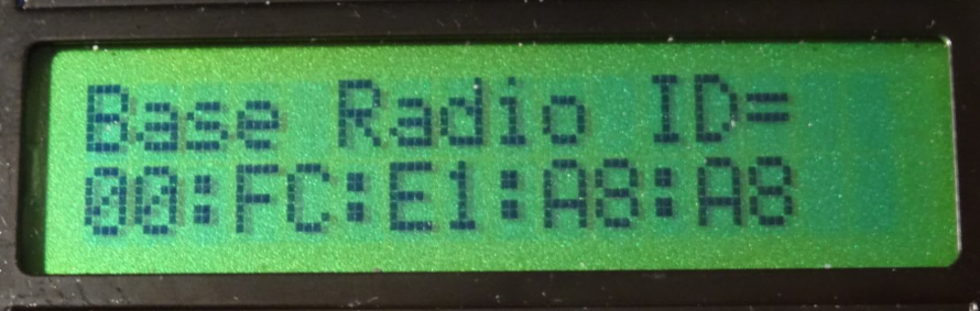
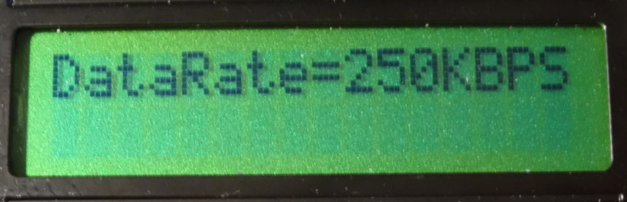
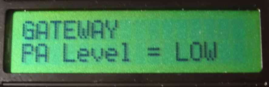
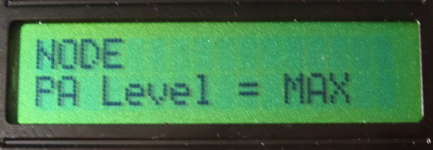
-
-
Hya,
correct me if i'm wrong.
To make use of this, two units must be built. One for node and other for gateway.
Is this undestanding correct? If not, how to use nRF24DoctorGateway and nRF24DoctorNode?
Thx in advance.
-
I need some help.
I just built an NRF24Doctor following the instruction in the post and on Github.-
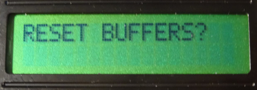
When no NRF24 module is connected, the device starts properly, displays the menu on the LCD, and when I try to select a menu item, it (correctly) displays "Radio init error. Replace radio".
-
When an NRF24 mode is connected (I tried several), the LCD is blank, the serial monitor shows "Channel:90 PaLevel:HIGH PaLevelGw:LOW DataRate:250KBPS Dest:0 Payload:2 Rate:10" in an endless loop.
-
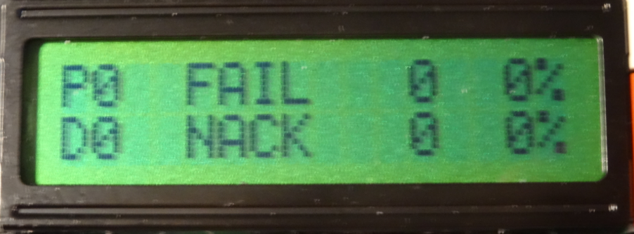
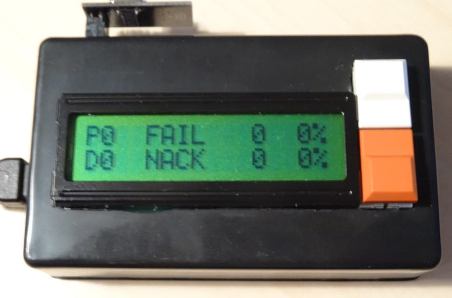
when I run the older "nRf24L01+ connection quality meter" software, it starts ok and the LCD shows FAIL 0% and MISS 0% as expected.
Any ideas for what might cause this problem? Almost looks like it resets in a loop, maybe because the watchdog triggers? or stack corruption?
-
-
Hello all,
First things first - this is a great device, kudos to everybody involved!
I built a buggy nrf24Doctor - it wasn't measuring the current consumption at all ("xxx Err" message). Trying to fix it led me to refactor the - splitting it into smaller "components" and adapting the project structure to VSCode/platform-io (ArduinoIDE is not my cup of tea).
If someone is interested, the code can be found at github.
Regards,
L. -
-
Sorry to necro this old post :(
I have just uploaded @yveaux's version of nRF24 doctor to a Nano.@Yveaux said in nRF24Doctor:
https://github.com/TechNovation01/nRF24Doctor/blob/master/pcb/nRFDoctor_1.1_sch.pdf
I got all the right libraries installed into IDE (especially LCDMenuLib2.h version 1.2.7, i also tried several other versions close to 1.2.7 just to be sure).
But when compiling i get the following errors :/tmp/ccMpih6l.ltrans0.ltrans.o: In function `global constructors keyed to 65535_0_nRF24QualityMeter03.ino.cpp.o.3416': <artificial>:(.text.startup+0x19a): undefined reference to `lcdml_menu_display()' <artificial>:(.text.startup+0x19c): undefined reference to `lcdml_menu_display()' <artificial>:(.text.startup+0x1a6): undefined reference to `lcdml_menu_clear()' <artificial>:(.text.startup+0x1a8): undefined reference to `lcdml_menu_clear()' collect2: error: ld returned 1 exit status exit status 1 Erreur de compilation pour la carte Arduino NanoThat is a bit above my knowledge. Could someone please point me into the right direction? Could it be just a case of "wrong naming" of variables ?
-
Sorry to necro this old post :(
I have just uploaded @yveaux's version of nRF24 doctor to a Nano.@Yveaux said in nRF24Doctor:
https://github.com/TechNovation01/nRF24Doctor/blob/master/pcb/nRFDoctor_1.1_sch.pdf
I got all the right libraries installed into IDE (especially LCDMenuLib2.h version 1.2.7, i also tried several other versions close to 1.2.7 just to be sure).
But when compiling i get the following errors :/tmp/ccMpih6l.ltrans0.ltrans.o: In function `global constructors keyed to 65535_0_nRF24QualityMeter03.ino.cpp.o.3416': <artificial>:(.text.startup+0x19a): undefined reference to `lcdml_menu_display()' <artificial>:(.text.startup+0x19c): undefined reference to `lcdml_menu_display()' <artificial>:(.text.startup+0x1a6): undefined reference to `lcdml_menu_clear()' <artificial>:(.text.startup+0x1a8): undefined reference to `lcdml_menu_clear()' collect2: error: ld returned 1 exit status exit status 1 Erreur de compilation pour la carte Arduino NanoThat is a bit above my knowledge. Could someone please point me into the right direction? Could it be just a case of "wrong naming" of variables ?
I might be able to answer that myself !
Looks like i have forgotten to "combine" a .ino file (CharLcdMenu.ino) with the main one (nRF24DoctorNode.ino), which seems to be a bit like a sub-program.
edit: that's it. Just had to create a second TAB with that sub-program, compile and success.
Please forgive my lack of vocabulary and knowldge, i am a "copy-paste" engineer :D
-
It's great when a project can be brought to life after 8 years!
-
It's great when a project can be brought to life after 8 years!
@OldSurferDude as long as we’re using nRFs this project is still relevant :D
I am now facing some more troubles:
The nRFNode cannot connect to GW.
Looks like a software issue. The exact same setup connects to GW when loaded with a very basic sketch (relay in my case). I am using @yveaux 's sketch from his Github.
Could this sketch not be compatible with today's API ? -
@OldSurferDude as long as we’re using nRFs this project is still relevant :D
I am now facing some more troubles:
The nRFNode cannot connect to GW.
Looks like a software issue. The exact same setup connects to GW when loaded with a very basic sketch (relay in my case). I am using @yveaux 's sketch from his Github.
Could this sketch not be compatible with today's API ?very basic sketch
My guess is that because you're not using the LCD in the basic sketch that talking to the LCD is causing radio interference.
To test this theory and assuming you have the LED connected, the LCD code could be replaced with flash-code code.
My technique for doing this replacement is to use compiler directives to remove the LCD code and add flash-code code.
To remove the LCD code, create a new compiler flag
#define LCD_ENABLE
Surround all LCD code with#ifdef LCD_ENABLE ... #endifThen comment out the definition line which disables the LCD.
Create another new compiler flag
#define FC_PIN 4
and comment out both the compiler directives that create TRIGGER_PIN and LED_PINAt the point in the existing code where the LCD is to display the quality, put a call to your new routine, This call will pass the quality number to the code that generates a flash code. So this new code can be easily disabled, surround your code with:
#ifndef FC_PIN
...
#endif
Yes, I make a huge assumption that you understand this (compiler directives, flash-code, etc.). If you don't, I, or others, can help out, but you'd learn more if you did it on your own.
-
very basic sketch
My guess is that because you're not using the LCD in the basic sketch that talking to the LCD is causing radio interference.
To test this theory and assuming you have the LED connected, the LCD code could be replaced with flash-code code.
My technique for doing this replacement is to use compiler directives to remove the LCD code and add flash-code code.
To remove the LCD code, create a new compiler flag
#define LCD_ENABLE
Surround all LCD code with#ifdef LCD_ENABLE ... #endifThen comment out the definition line which disables the LCD.
Create another new compiler flag
#define FC_PIN 4
and comment out both the compiler directives that create TRIGGER_PIN and LED_PINAt the point in the existing code where the LCD is to display the quality, put a call to your new routine, This call will pass the quality number to the code that generates a flash code. So this new code can be easily disabled, surround your code with:
#ifndef FC_PIN
...
#endif
Yes, I make a huge assumption that you understand this (compiler directives, flash-code, etc.). If you don't, I, or others, can help out, but you'd learn more if you did it on your own.
@OldSurferDude thank you very much for taking time to explain.
I didn't make it clear enough from my side though.
My "test" setup here is not the whole "nRF Doctor", as i got fed up with it !!
Last night i just grabbed a Nano and a red nRF (eByte).
Then loaded a random basic sketch and it got connected to GW straight away.
After that i loaded @yveaux 's sketch and it never reached the GW (although changes were made to sketch, such as default channel (76), power level and transmission speed. These changes were made to files located in the "share" directory, that are called via "#include").
Yveaux's sketch is based on API ver 2.2.0... latest stable is 2.3.2. So i tried different versions other than 2.3.2 but they all ended up with errors when compiling.I'll keep on digging tonight anyway (and report errors).
-
Quick update:
-compiling with MySensors librairy ver 2.3.2 gives no error but my simple setup cannot reach GW with the following debug on serial monitor:0 MCO:BGN:INIT NODE,CP=RNNNA---,FQ=16,REL=255,VER=2.3.2 4 MCO:BGN:BFR 35 TSM:INIT 36 TSF:WUR:MS=100 43 TSM:INIT:TSP OK 45 TSM:INIT:STATID=250 47 TSF:SID:OK,ID=250 49 TSM:FPAR 72 ?TSF:MSG:SEND,250-250-255-255,s=255,c=3,t=7,pt=0,l=0,sg=0,ft=0,st=OK: 137 MCO:BGN:STP 151 TSF:WUR:MS=2000 2080 !TSM:FPAR:NO REPLY 2082 TSM:FPAR 2105 ?TSF:MSG:SEND,250-250-255-255,s=255,c=3,t=7,pt=0,l=0,sg=0,ft=0,st=OK: 2166 MCO:BGN:INIT OK,TSP=0 4113 !TSM:FPAR:NO REPLY 4115 TSM:FPAR 4139 ?TSF:MSG:SEND,250-250-255-255,s=255,c=3,t=7,pt=0,l=0,sg=0,ft=0,st=OK: 6147 !TSM:FPAR:NO REPLY 6149 TSM:FPAR 6172 ?TSF:MSG:SEND,250-250-255-255,s=255,c=3,t=7,pt=0,l=0,sg=0,ft=0,st=OK: 8180 !TSM:FPAR:FAIL 8181 TSM:FAIL:CNT=1 8183 TSM:FAIL:DIS 8185 TSF:TDI:TSL 18187 TSM:FAIL:RE-INIT 18189 TSM:INIT 18195 TSM:INIT:TSP OK 18197 TSM:INIT:STATID=250 18200 TSF:SID:OK,ID=250 18202 TSM:FPAR 18225 ?TSF:MSG:SEND,250-250-255-255,s=255,c=3,t=7,pt=0,l=0,sg=0,ft=0,st=OK: 20233 !TSM:FPAR:NO REPLY 20235 TSM:FPAR 20258 ?TSF:MSG:SEND,250-250-255-255,s=255,c=3,t=7,pt=0,l=0,sg=0,ft=0,st=OK: 22266 !TSM:FPAR:NO REPLY 22268 TSM:FPAR 22291 ?TSF:MSG:SEND,250-250-255-255,s=255,c=3,t=7,pt=0,l=0,sg=0,ft=0,st=OK: 24299 !TSM:FPAR:NO REPLY 24301 TSM:FPAR 24324 ?TSF:MSG:SEND,250-250-255-255,s=255,c=3,t=7,pt=0,l=0,sg=0,ft=0,st=OK: 26332 !TSM:FPAR:FAIL 26333 TSM:FAIL:CNT=2 26335 TSM:FAIL:DIS 26337 TSF:TDI:TSL 36340 TSM:FAIL:RE-INIT 36342 TSM:INIT 36348 TSM:INIT:TSP OK 36350 TSM:INIT:STATID=250 36354 TSF:SID:OK,ID=250 36356 TSM:FPAR 36379 ?TSF:MSG:SEND,250-250-255-255,s=255,c=3,t=7,pt=0,l=0,sg=0,ft=0,st=OK:and so on
- compiling with MySensors librairy ver 2.2.0 (as mentionned in the sketch) gives me the following error:
Compilation error: 'RF24_PA_LOW' was not declared in this scope- same error with MySensors librairy ver 2.3.0
-
I vaguely remember that the RF24_PA_[power level] was given a different name. to something different. Basically the power level is 0,1,2, or 3 (MIN, LOW, HIGH, or MAX). see docs
To get it to compile, put this (a hack) line in
#define RF24_PA_LOW 1
before line 47
#include "shared/RadioConfig.h"
or before
radio.setPALevel(RF24_PA_LOW);I had forgotten about this. Maybe the problem is that that power level is set to low. I see in RadioConfig.h it's set to LOW. This is done because the two radios could be close to one another and they would overdrive the other if they're set to MAX
Another thought (my little gray cells are not firing on all cylinders) It seems to me that line 47
#include "shared/RadioConfig.h"
should be after line 59
#include <MySensors.h>
because the MySensors library is where the PA variables are set.I hope my rambling here hasn't further complicated the issue.
-
I vaguely remember that the RF24_PA_[power level] was given a different name. to something different. Basically the power level is 0,1,2, or 3 (MIN, LOW, HIGH, or MAX). see docs
To get it to compile, put this (a hack) line in
#define RF24_PA_LOW 1
before line 47
#include "shared/RadioConfig.h"
or before
radio.setPALevel(RF24_PA_LOW);I had forgotten about this. Maybe the problem is that that power level is set to low. I see in RadioConfig.h it's set to LOW. This is done because the two radios could be close to one another and they would overdrive the other if they're set to MAX
Another thought (my little gray cells are not firing on all cylinders) It seems to me that line 47
#include "shared/RadioConfig.h"
should be after line 59
#include <MySensors.h>
because the MySensors library is where the PA variables are set.I hope my rambling here hasn't further complicated the issue.
@OldSurferDude thanks once again for taking time to understand my problem !
Moving
#include "shared/RadioConfig.h"after
#include <MySensors.h>got me the following compile error
In file included from /home/ben/Documents/Arduino/nRF24QualityMeter03/nRF24QualityMeter03.ino:58:0: /home/ben/Arduino/libraries/MySensors/MySensors.h:426:2: error: #error No forward link or gateway feature activated. This means nowhere to send messages! Pretty pointless. #error No forward link or gateway feature activated. This means nowhere to send messages! Pretty pointless. ^~~~~ exit status 1 Compilation error: exit status 1 -
I'm thrashing on this, too, so I downloaded it and I compiled it.
Downloading:
- From the web page I clicked on [Code] and then downloaded the zip file.
- I extracted the zip file to my Arduino directory.
- In a dos box (command line) I changed to Arduino\nRFDoctor-master
- I executed the batch program
mklink.batwhich created symbolic links in bothnRF24DoctorGatewayandnRF24DoctorNodeto their sister directoryshared. This is needed so that the compiler can find the project specific libraries, egRadioConfig.h
Then I opened
nRF24DoctorNodein the Arduino IDE 2.3.10When first compiling, there were many libraries required which I installed.
After all the libraries were installed, the code had the compiler check a value and if it was incorrect, it threw an error. When the line
#define _LCDML_DISP_cfg_max_rows 2was added to the the libraryLCDMenuLib2.hat line 42, the error no longer occurred. (Was this a good thing? Perhaps the line should have gone just before the error check?) This library is found in the directory Arduino\libraries\LCDMenuLib2\srcSubsequently The compiler recommend changing the line 28 of CharLcdMenu.ino (
tmp = LCDML.MENU_getObj()->getChild(LCDML.MENU_getScroll());) totmp = LCDML.MENU_getRootObj()->getChild(LCDML.MENU_getScroll());After that, the code compiled.
-
I'm thrashing on this, too, so I downloaded it and I compiled it.
Downloading:
- From the web page I clicked on [Code] and then downloaded the zip file.
- I extracted the zip file to my Arduino directory.
- In a dos box (command line) I changed to Arduino\nRFDoctor-master
- I executed the batch program
mklink.batwhich created symbolic links in bothnRF24DoctorGatewayandnRF24DoctorNodeto their sister directoryshared. This is needed so that the compiler can find the project specific libraries, egRadioConfig.h
Then I opened
nRF24DoctorNodein the Arduino IDE 2.3.10When first compiling, there were many libraries required which I installed.
After all the libraries were installed, the code had the compiler check a value and if it was incorrect, it threw an error. When the line
#define _LCDML_DISP_cfg_max_rows 2was added to the the libraryLCDMenuLib2.hat line 42, the error no longer occurred. (Was this a good thing? Perhaps the line should have gone just before the error check?) This library is found in the directory Arduino\libraries\LCDMenuLib2\srcSubsequently The compiler recommend changing the line 28 of CharLcdMenu.ino (
tmp = LCDML.MENU_getObj()->getChild(LCDML.MENU_getScroll());) totmp = LCDML.MENU_getRootObj()->getChild(LCDML.MENU_getScroll());After that, the code compiled.
@OldSurferDude that is ever so kind of you to provide such quality support !!
So far so good : i took a different path but got to the same point.
Line 73 of nRF24DoctorNode.ino mentions
#include <LCDMenuLib2.h> // Download 1.2.7: https://github.com/Jomelo/LCDMenuLib2Compile error probably comes from here. I installed older version (current is 2.2.8, recommended is 1.2.7), as requested.
I manually installed all the *.h files and got it to compile (with MySensors 2.3.2, any other older version would not compile).
At that point did you upload that sketch to a nano+nrf for testing ?
EDIT : that "mklink" thing is specific to Windows right ? Does it do more magic than just copying shared files at the root of the nRFdoctor's directory ? I only have Linux computers at home...
-
mentions
I suspect that the library has been included in the Arduino repository. I used the IDE library manager to install it.
At that point did you upload that sketch to a nano+nrf for testing ?
I haven't done any hardware testing. I'll leave that for you.
"mklink" thing is specific to Windows right ?
Yes, mklink.bat is for Windows only. This script is the linux equivalent.
# assumes the existence of the folder shared in the current directory. cd nRF24DoctorNode ln -s ../shared shared cd .. cd nRF24DoctorGateway ln -s ../shared shared cd .. -
So i spent some time on that subject this past weekend...
Unfortunately I did not learn anything nor got any good outcome.
Every sketch has been tested on two seperate bits of hardawre : my custom built nRFDoctor and a random Arduino Nano.
Fresh install of Yveaux's sketches, with official script to create symbolic links.
All compiled nicely but none got to connect to GW.
On the other hand, both units managed to register to the GW with a very basic sketch (relay sketch).
-
I see that the the nRFDoctor has a menu. Perhaps one of the menu items has to be selected?



Hello! It looks like you're interested in this conversation, but you don't have an account yet.
Getting fed up of having to scroll through the same posts each visit? When you register for an account, you'll always come back to exactly where you were before, and choose to be notified of new replies (either via email, or push notification). You'll also be able to save bookmarks and upvote posts to show your appreciation to other community members.
With your input, this post could be even better 💗
Register Login