Relay sensors stop communicating with gateway after a few minutes


  • So I have two relay sensors that I use to control my sprinklers.

    They sit in my garage on the wall right by each other as displayed in the picture. When I restart the sensors they work just fine for about 20 minutes, and then for some reason they stop communicating with the gateway and I cant control them from the Vera UI anymore. I click the ON/OFF buttons and nothing happens.

    Has anyone had this problem before? I wonder if the fact that they are sitting right by each other has anything to do with it. Maybe the radio receivers are interfering with each other?

    I am using Arduino nano and MySensors Library 1.4. Any help is appreciated!

    Thanks

    IMG_0234.JPG


  • Hardware Contributor

    I dont know exactly but look at petewills relay exemple. Maybe it helps with caps to reduce noice to the radio when relay activates and 4.7uf CAP on radio. I had this issue and it was the radio to close (in till between) other components making The signal to weak. When the relay didnt get ack back it locked.


  • Admin

    Also try feeding the realys directly from the 5V input from the charger.


  • Contest Winner

    you may also wish to consider controlling both relays from the same Arduino and same radio.

    I've never placed two nodes so close to each other, but I imagine that all the EMF activity in that compact space... there is a potential for a lot to go wrong.


  • @BulldogLowell
    That is a good idea. But if I do so, can I choose which relay I want to turn on/off from the UI? The water pressure here is not very strong, so I need to turn on only one irrigation channel at a time. But I will give that a try anyways!

    Thanks!


  • Contest Winner

    Most definitely!!!


  • @hek said:

    Also try feeding the realys directly from the 5V input from the charger.

    I tried doing that, but when I feed the relay with the external 5v supply they wont work. The power light turns on and looks good, but when I click on/off in the UI the relay wont switch. Do I need to do anything special to power the relays directly from the charger?

    Thanks!


  • Contest Winner

    @rafael.brasilia said:

    Do I need to do anything special to power the relays directly from the charger?

    Yes, a larger power supply.

    typical iPhone charger is 5Watt or about 1A @5V

    you may need to look at 10-15Watt power supplies, or 1500-2000mA @5V

    try iPad charger... if you have access to one.


  • @BulldogLowell

    I tried the ipad charger and still no luck. I also tried another power supply with output 2.5A @5V and it didnt work. Now I'm just curious, if I need a bigger power supply to power the relay, how come the Arduino is able to power it from it's 5V output?

    Thanks for the help!


  • Try to move your AC cables a little bit away from the nodes. Just to avoid any possible EMF activity.


  • Hardware Contributor

    It should be fine and click/on off with that power supply.
    Are you using a 5v relay? I ordered 5v relays but got 12v relays instead... same symptoms, all leds worked but no click.
    It should say SRD-05VCS on top on the blue relay.


  • @sundberg84
    Mine says SRD-05VDC-SL-C on top. Im pretty sure this is a 5v because it works fine when powered from the Arduino 5v output. I just wanted to connect it to an external power source because I have two relays connected to my Arduino now and that might bee too much for it to handle.


  • Contest Winner

    Try separating them, or just one powered at a time so you are sure that they are not bothering each other. As mentioned above have you added capacitors to the power to the radios?

    See if you can get only one (or each separately) working, that rules out interference.

    If that solves your problem, then just use one arduino to control both relays, which is the way most of us would do it in your use case. The extra radio an arduino are a bit superfluous.


  • So my problem is definitely that the Arduino is not strong enough to power the relays. When the relays are not powered by the Arduino, my sensor communicates with the gateway just fine. It's been on for more than 24 hours now and still communicating fine.

    I found this somewhere else, and I think it's exactly what was happening:
    "if you draw too much power from the +5V, the thermal protection circuit on the voltage regulator will trip and the whole Arduino will shut down"

    So I just need to find a way to power the relays from an external power source. Has anyone done that?
    I've tried several different power sources, and with all of them the relay LEDs turn on but it won't click when turn it on/off. I even tried powering the relay from another Arduino just to make sure the voltage was right, but still no luck.

    Thanks!


  • Contest Winner

    @rafael.brasilia

    Reference this you should be powering the relays from Vin which is directly powered (5V) from your USB cable and is not regulated by the Arduino. in other words, the power at Vin is regulated by your power adaptor.

    The 5V (AKA Vcc) pin is using the Arduino's on-board regulator, and indeed the current is limited by that device. If you power your arduino with the Raw pin, using a 9V battery for example, the Arduino's on-board regulator will drop that voltage to 5V, thus its marking.

    I hope that's clear.


  • Hardware Contributor

    Perhaps someone w/ more electronics knowledge can comment more but in my limited research, you can reduce power consumption to the relay by getting one w/ an optocoupler. There is a good write up here: https://arduino-info.wikispaces.com/RelayIsolation

    Most x2, x4, and x8 relays on aliexpress that I have seen have optocouplers. Here are some single relay boards with them: http://www.aliexpress.com/item/Free-shipping-5Pcs-Lot-Level-Triger-Optocoupler-Relay-1-Channel-H-LModule-for-Arduino-5V-New/32390536994.html


  • Hero Member

    @TD22057 The relay coil will draw a certain amount of current at 5 VDC. Using opto-couplers does not change the amount of current the relay draws. However, some of the relay modules will use transistors, etc. to ensure that the current for the coil is not supplied by the digital output pin of the Arduino as the output pins can't typically source enough current for that.

    Cheers
    Al


  • Hero Member

    It's a strange problem. In most of my "projects" I power the relays directly from the power supply, home built or mfg and other than adding some capacitors have not seen these problems. Now I aways use Opto-controled relays so I don't have to use any diodes...


  • @ServiceXp
    What kind of power supply do you use to power the relays? I've tried several different options (iPhone charger, iPad charger, and various other 5v power supplies) but no luck. The LEDs on the relay turn on, but it doesn't click. Would you have a picture of one of your relays so I can see your setup?

    I also tried following the advice from @BulldogLowell and powered the relays from the VIN pin instead of the Arduino 5v output, but I had the same problem. The relay worked for a few hours, then stopped working.

    FYI: I am using a relay with optocoupler just like the one posted in the link above. Maybe I just got a batch of bad Arduinos from China?

    Thanks!


  • Hero Member

    @rafael.brasilia I'm wondering if the relays are actually 9VDC or 12VDC relays that are misprinted as 5VDC. What happens if you power them with a 9V battery as a quick test? I use old phone chargers with similar 5V relays and never had an issue with powering them that way. Do you have any other relays you can test with?

    Cheers
    Al


  • Hardware Contributor

    I thought the same, it was how i detected i had 12v relays instead of 5v. I just quickly powered with 9v bat and then the relay clicked.


  • Thanks for the heads up. But I tried 9v and 12v and no luck! They only click when powered directly from the Arduino and they stop working after a few hours.


  • You should probably draw a circuit diagram about your connections?


  • @Nuubi
    This is how I have my connections:
    Relay Diagram.png

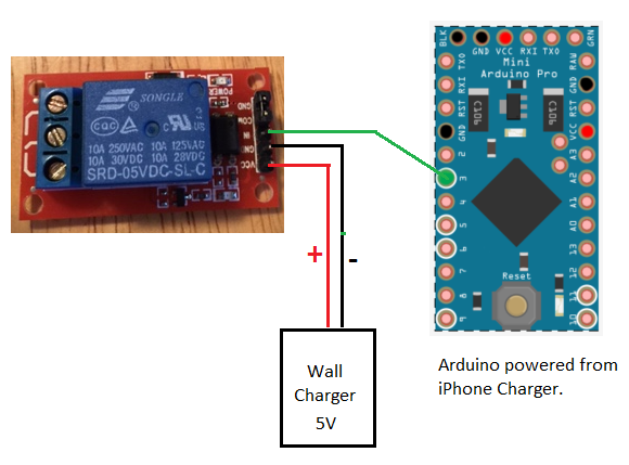
    Is there anything wrong with it?
    Thanks!


  • Hero Member

    Try adding a wire between the GND on your relay board and GND on your arduino. Even if they have seperate power source you stil need to connect GND between them.


  • Exactly that is the reason. Yep.


  • YES!!! That was it! I got both relays powered from the external power supply now and everything seems to be working fine.
    Thank you all very much!


Log in to reply
 

Suggested Topics

  • 3
  • 3
  • 2
  • 4
  • 2
  • 2

1
Online

11.2k
Users

11.1k
Topics

112.5k
Posts