[SOLVED] 2 X nrf24l01+pa+lna with RF24_PA_MAX


  • I got problems with using 2 modules nrf24l01+pa+lna with the PA_LEVEL configured to RF24_PA_MAX.
    I'm using one module on the gateway with the MySensor Serial Gateway Sketch the other module on a Arduino nano with a sketch that simply sends a fixed value to test the connection.

    Both modules are directly powered by 2xAA batteries buffered by 220ยตF capicitors.

    The strange thing i experience is: They don't communicate to each other, only if i put my hand arround one of the antenna the packets starts to flow.
    Increasing the distance between both modules don't work.

    Anyone has an idea what could be wrong?

    Solved with: http://blog.blackoise.de/2016/02/fixing-your-cheap-nrf24l01-palna-module/


  • Hero Member

    I would guess that you are using the stubby linear antennas, with both antennas parallel to each other and at right angles to the line between the units. Like both antennas pointed up, with the units at some horizontal distance from each other. (The antennas will radiate/receive best at right angles to where they are pointing, and least along the line of where they are pointing - both directions - so pointing the antennas at each other is not good.)

    Have you tried reducing the power level?

    Do you have any regular models without PA+LNA+external antenna? You might try interoperating with them, for another data point.

    RF is weird sometimes.


  • @Zeph your guess is correct, i should have written that.
    Yes i tried to reduce the power level, they work on a low-high power level up to 400-600m free sight distance.
    But because i wanted to get out the greatest distance, it would be nice to get them up to the max level.

    The strange thing is that holding my hand arround one of the antennas get the packets flowing.
    In my understanding holding my hand around the antenna should normaly shield the RF.. instead it just works o_O.


  • Hardware Contributor

    I've been having reception problems myself (so I'm planning on switching to RMF69W modules) and have been reading more about antenna design since I want to create a custom PCB (and basically learning that I'll probably never know enough to be good at RF). You might be having ground plane issues - it can also help to try moving the radio module away from any other boards and metal surfaces near it and see if that helps too.


  • Well... i never opened one of these standard 2,4ghz stubby antennas but i guess there is a little groundplane in there on the bottom of the antenna directly after the joint.
    It isn't that i got directly reception problems... 400-600m sounds good in my opinion. But working with the maximum i can get, would be nice...

    Little bit offtopic: Whats the maximum distance the RMF69W working on? Whats the datarate they deliver? I know that the RFM69W modules work on 868mhz so they naturally should work on a longer distance, but most 868mhz chips don't even reach the minimum datarate of 250kbps...


  • Tested a little bit more. I have the strange feeling that setting the PA_LEVEL higher then LOW overdrives the nrf24l01+pa+lna. Has anyone ever used this modules with a PA_LEVEL higher then low?


  • I use it at max and it works fine. How do you feed the 3.3V of the nrf? I use a AMS1117 (up to 800mA).


  • External 2xAA batteries for my tests. In the final use case I will add a 3.3V voltage regulator. I got a tip yesterday that this could be a matter of inproper shielding to the module itself. Sounds like a plausible explanation to me. I will try today to shield the module from his own rf with tin foil.


  • Just if anybody else is running into this problem:
    Shielding the module with tinfoil against RF worked great! With the tinfoil shield i got over 1km reach in a clear line of sight!


  • Hero Member

    Wow. A little better!

    I assume that's at 250 Kbps? Did you do any range tests at different speeds?

    The nRF24L01+ with LNA & PA & antenna is not that much more expensive than the rfm69* so for some applications that need the higher speed they are still in the running even with longer distances.

    I saw an analsyis (maybe here?) which suggested that this setup would not do very much good for reception, which was more limited by the noise floor, such that the antenna gain and LNA would not improve things much - so most of the range gain would come from the increased transmit power (including antenna gain). This was a theoretic analysis, not an empircal test.

    If true, it would mean that using an enhanced power unit on one end of the link only would not give one much additional range in bidirectional protocols, where the back-link (conventional to enhanced) would be the limiting factor. I've been curious if this is indeed the case or not in practice.


  • @Oitzu do you have some photo of your module with shielding ?


  • @Zeph Only tried 250kbps at the moment, i tried to test the maximum range possible.
    But i will also do some 1mbit and 2 mbit tests in the near future (depends on weather).

    Hm.. i don't know what exactly do the performance gain. I also ordered some modules with external antenna but without external LNA+PA. Let's see what the LNA+PA really do. ๐Ÿ˜‰

    @Fabien: I will post a photo tomorrow. But basicly i just wraped cling film arround the module (to not get any shorts) and then wraped tin foil arround that.


  • @Fabien:
    2015-08-31 09.01.05.jpg

    Surely doesn't look "professional" but it works. In the final installation i will try to add aluminum tape to the inside of the project box.


  • Hero Member

    @Oitzu The range was greatly improved by using a far-aday cage.


  • @Zeph: Yeah i understand that. I meant if the pa all alone or if the lna also plays a role with this modules.
    Because you mentioned that the lna probably doesn't play a role in this.


  • Thank you !


  • Hero Member

    @Zeph said:

    @Oitzu The range was greatly improved by using a far-aday cage.

    Sorry, it was meant to be a throw-away pun, not an insight.


  • @Zeph said:

    @Zeph said:

    @Oitzu The range was greatly improved by using a far-aday cage.

    Sorry, it was meant to be a throw-away pun, not an insight.

    ... now i got it... haha... sorry. You know how many germans does it takes to change a lightbulb?
    One. We are very efficient and don't have humour. ๐Ÿ˜‰


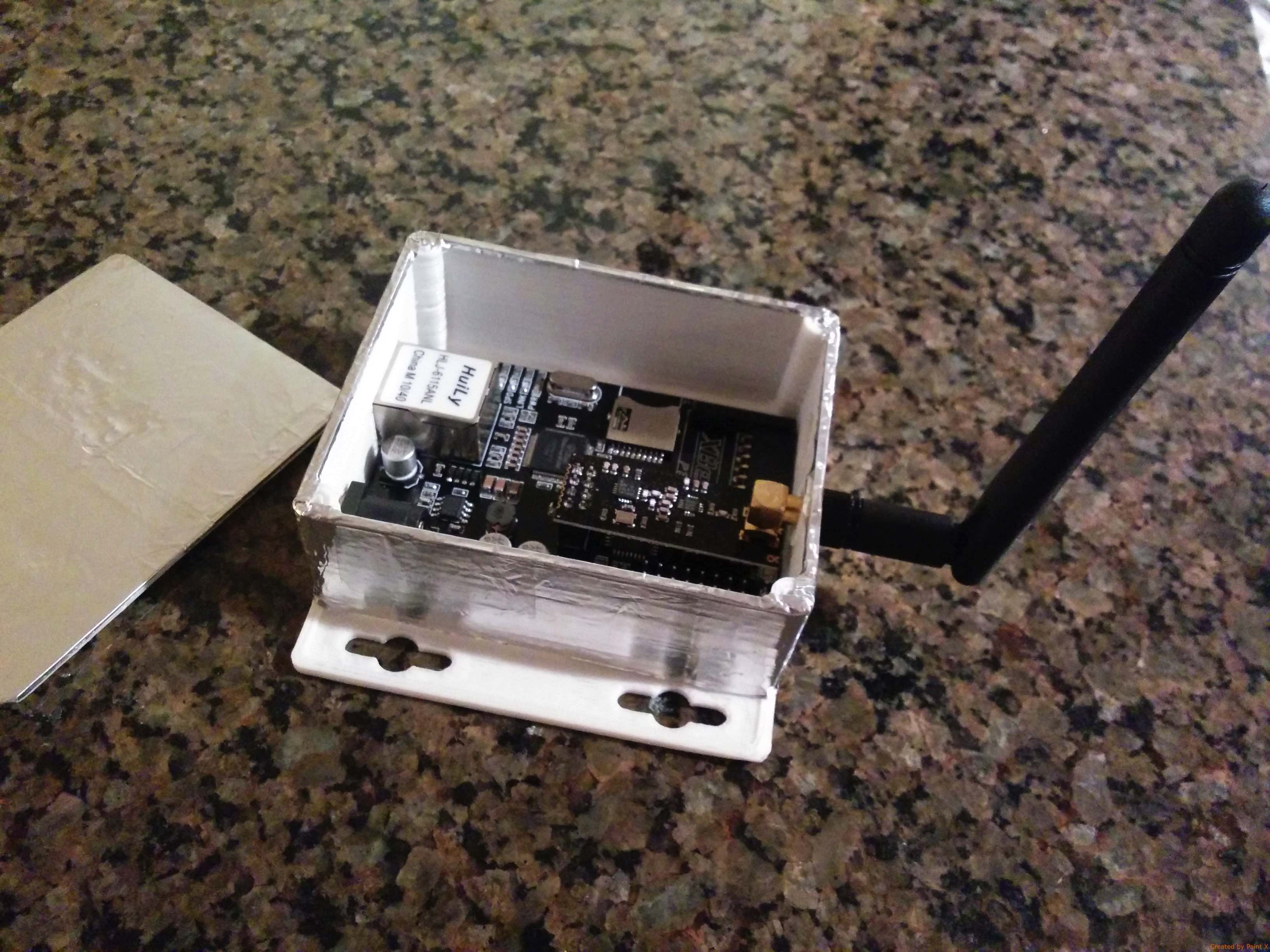
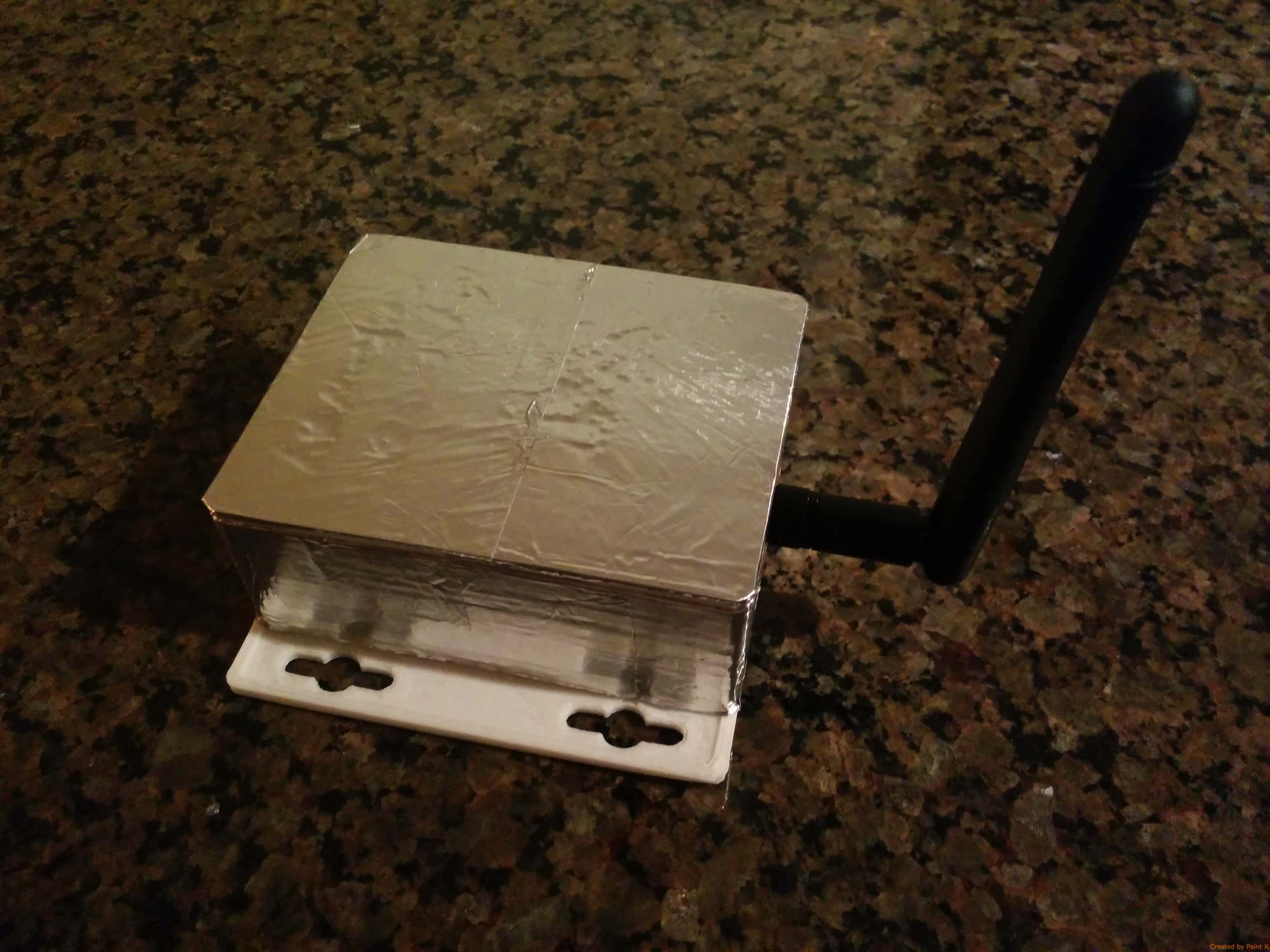
  • @Oitzu questions: on the picture, the foil cover up the base of the antenna. Can it touch the antenna connector itself (golden part the antenna is screw on) or this part also need to be covered with plastic film ?

    You also told you will try to cover up the inside of the case with foil to not wrap the radio itself... did you try it ?


  • @wico2002: you should also cover the base of the antenna with plastic foil.
    As far as i know the base is grounded. I don't really know if this makes any difference but i let my tinfoil ungrounded. I'm no expert in RF mechanics. ๐Ÿ˜„

    No not tried this yet.. but this should have the same effect as the tinfoil wrapping.
    As long as you let stick the antenna out of the housing.... ๐Ÿ˜‰


  • @Oitzu A BIG THANK YOU, it work now with the foil trick. I'll will maybe close other forum topics including your topic's url. thank you again


  • Using @Oitzu 's trick, I wrapped my iBoard Gateway in aluminum tape. I can't tell if there is any benefit in transmission range or reduced interference but at least it looks nice and shiny!

    IMG_20151007_213755.jpg

    IMG_20151007_213811.jpg


  • @Dwalt will this box also sends packets to the path of valallah?
    Screenshot 2015-10-08 09.27.25.png


  • @Oitzu Yes, now my network will ride eternal!

    Actually, my brother saw the modification and asked if I was trying to prevent the NSA from intercepting my humidity readings. Hmmm, maybe a secondary benefit...

    rob-tinfoil-hat-compressed.jpg


  • Finally does the foil should be grounded or not ??
    thanks


  • Mod

    Grounding the foil will not affect the shininess, but it could improve the shielding.


  • @mfalkvidd thanks for your reply.
    If we want to ground it, can we use the gold base ? I guess that this part is grounded....

    I met some issues with PA LNA, do you think that it can freeze after a while, and powering the NRF24+PA+LNA directly on the nano ? It seems that after one month of use, I loss many packets..


  • @doblanch well the theory says it should be grounded so the signals induced into the foil can "flow" to ground instead to build up a current in the foil. (But make sure to just connect ground to one side of the foil, connecting on multiple points can produce a ground loop)
    I havn't tested if the "gold" base is grounded, maybe just check with an multimeter?
    Also i have fine results with grounded and ungrounded shield.

    The PA/LNA shouldn't be powered directly from the nano. The voltage regulator on the nano will probably not deliver enough current to stable power the PA/LNA modul on the high power settings.


  • @Oitzu Thanks. I will test it ungrounded first.
    For the nano thanks also for your reply, it's great to have confirmation that nano can not really support NRF+PA+LNA with RF24_PA_MAX parameter, which is my case.
    I hope , that powering direclty from a USB will avoid any more issue, that I'm hitting...
    thanks again


  • @doblanch said:

    I hope , that powering direclty from a USB will avoid any more issue, that I'm hitting...

    Keep in mind that USB is 5V and the nrf24l01+ takes 3.3V on VCC.


  • @Oitzu Yes of course, I'm using a Buck power down socket ( the one recommended on mysensor.org)
    thanks


Log in to reply
 

Suggested Topics

20
Online

11.2k
Users

11.1k
Topics

112.5k
Posts