Relay Help - Nothing Happens
-
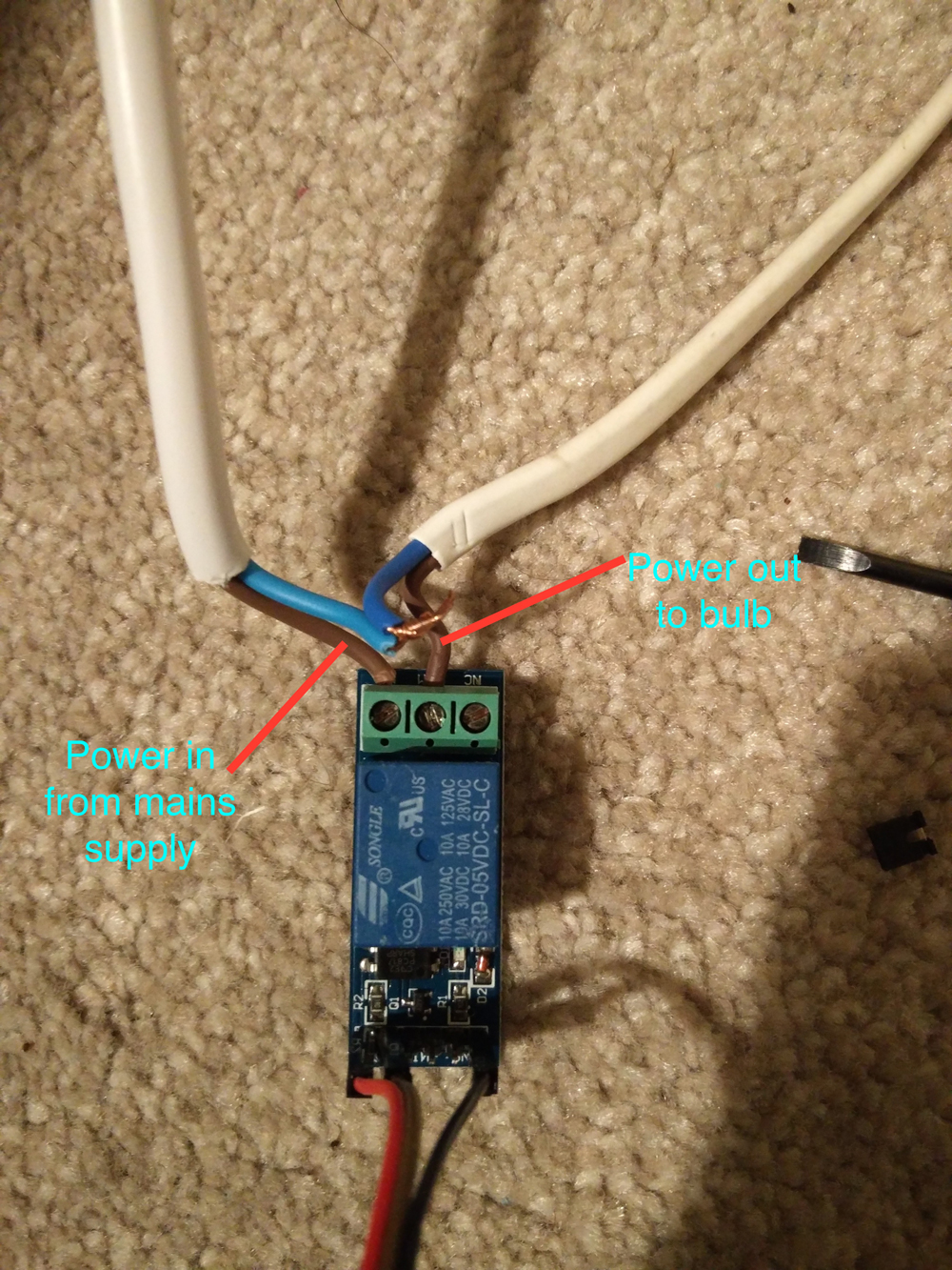
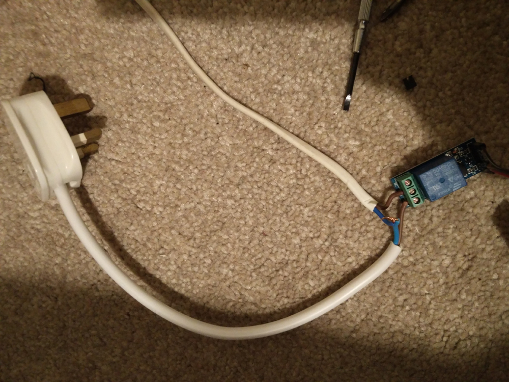
Hi I have just put together my first relay to test, based on the relay mysensors sketch.
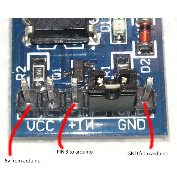
I have connected up the relay as shown in the photo below, but I'm a little unclear about the connections to the arduino. I have it connected to a nano for testing, GND and 5V seem obvious but there are three other pins on the relay, plus a jumper?? so I don't know which to connect the digital pin to. I have also tried all the options, but there relay does not seem to work, although I can see messages coming into my broker just fine. I assumed I would hear the relay switch on and off even if it's not connected into the mains outlet, is that correct?
Regardless of this even when I plug in wall socket for the bulb in it still does not work so I'm at a loss as to what is wrong :-(
Maybe I'm missing something really obvious here so an support would be much appreciated.
-
Where did you buy the relay -- any documentation for that?
Looks like it has options for isolating the power source from the arduino power, see e.g. http://www.forward.com.au/pfod/HomeAutomation/OnOffAddRelay/index.html
(Can't see the markings really on the module to see what each pin refers to) -
Where did you buy the relay -- any documentation for that?
Looks like it has options for isolating the power source from the arduino power, see e.g. http://www.forward.com.au/pfod/HomeAutomation/OnOffAddRelay/index.html
(Can't see the markings really on the module to see what each pin refers to)@Nuubi thanks I got the replay from eBay. The only markings are vcc gnd and -in+. However there are 6 pins. Which makes it a little more confused.
-
@Nuubi thanks I got the replay from eBay. The only markings are vcc gnd and -in+. However there are 6 pins. Which makes it a little more confused.
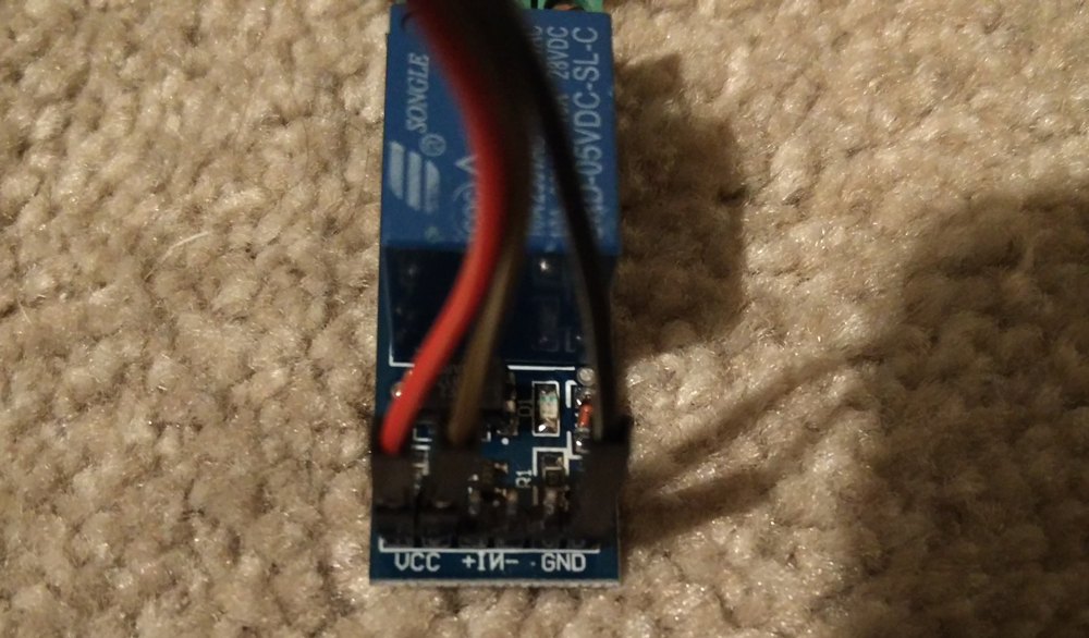
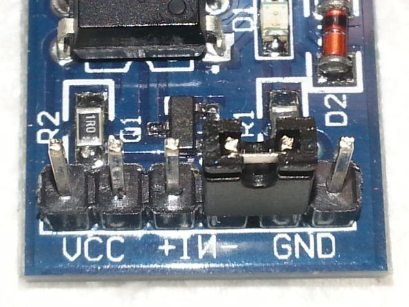
Here are the pins on my relay, because there are multiple pins and the jumper i'm rather confused
-
Hi Matt
Here is a picture of a relay board that i have
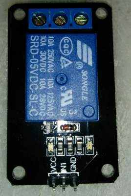
to get the relay to work with this board I need to connect +5v to the vcc terminal
The GND to negative
and supply negative to the In1 terminaland yes it does make an audible click when it operates
I have not used a relay like yours before but suspect the jumper could be used to select if you want to switch the relay with a high or low (positive or negative) signal. for example in the position you show it in your last picture you would need to connect VCC to +5v , GND to the negative rail and supply +5v to the +IN terminal to make it work. my relay will happily work on 3v so if you have a couple of 1.5v batteries lying around you could use them to see if it works. once you know how to trigger the relay then you can look further for the problem
I would do your testing without any mains connected as well just to keep it all safe, you will hear the relay click when it works even without the mains connected
-
Hi Matt
Here is a picture of a relay board that i have
to get the relay to work with this board I need to connect +5v to the vcc terminal
The GND to negative
and supply negative to the In1 terminaland yes it does make an audible click when it operates
I have not used a relay like yours before but suspect the jumper could be used to select if you want to switch the relay with a high or low (positive or negative) signal. for example in the position you show it in your last picture you would need to connect VCC to +5v , GND to the negative rail and supply +5v to the +IN terminal to make it work. my relay will happily work on 3v so if you have a couple of 1.5v batteries lying around you could use them to see if it works. once you know how to trigger the relay then you can look further for the problem
I would do your testing without any mains connected as well just to keep it all safe, you will hear the relay click when it works even without the mains connected
@Boots33 Thanks for your input, its much appreciated. I have connected 5v from the nano to VCC GND to GND pin on the nano and my arduino digital pin 3 to +IN
When I do the above the LED on the relay lights up to I know its getting power and I hear it click when I initially power the whole thing up. I have also tested plugging into the power outlet and the light is on, so I know that power is getting through.
But when I send the on off command from within my openhab setup I see the messages being published on my broker but they do not switch the relay on or off
-
@Boots33 Thanks for your input, its much appreciated. I have connected 5v from the nano to VCC GND to GND pin on the nano and my arduino digital pin 3 to +IN
When I do the above the LED on the relay lights up to I know its getting power and I hear it click when I initially power the whole thing up. I have also tested plugging into the power outlet and the light is on, so I know that power is getting through.
But when I send the on off command from within my openhab setup I see the messages being published on my broker but they do not switch the relay on or off
@Matt-Pitts said:
When I do the above the LED on the relay lights up to I know its getting power and I hear it click when I initially power the whole thing up. I have also tested plugging into the power outlet and the light is on, so I know that power is getting through.
By your picture the light looks like you have it connected to the Normally open side of the relay so if it is on that would indicate the relay is on as well. So it is not changing state when you issue a command.
some things to try
Have you modified the original sketch at all. if so could you post it .
Is your sensor too far away from the gateway? try moving it a bit closer to make sure it is in range.
To help with testing you may want to remove the relay and just put a led(and resistor) on the output pin of the arduino, this will give you a visual indication of the changing of state. then with the arduino hooked to your computer open up the arduino serial monitor and see if any of the debug messages give a clue as to what is happening.
-
@Boots33 thanks, I'm using the sketch unaltered. When I check the serial monitor I can see the messages coming in 0 and 1 so I know the connection to the broker and therefore the radio must be working right? otherwise the messages wouldn't show up on the serial monitor right? also I see st:OK in the monitor which means messages are being delivered, is that right?
Weirdly though I thought that once I connected 5v from the arduino to VCC and GND to GND the relay would power up, but this doesn't happen?? The relay only powers up when I connect the pin 3 to the relay. In fact it I connect the 5V from the arduino to the +IN that also powers the relay. Sorry I'm relatively new to all this and only have a very basic understanding so apologies for so many questions.
I'm wondering if I need to alter the sketch in some way?? My current pin connections are show below in the photo. If I remove the jumper the relay doesn't work at all??
@Matt-Pitts said:
@Boots33 thanks, I'm using the sketch unaltered. When I check the serial monitor I can see the messages coming in 0 and 1 so I know the connection to the broker and therefore the radio must be working right? otherwise the messages wouldn't show up on the serial monitor right? also I see st:OK in the monitor which means messages are being delivered, is that right?
Yes that is how i understand it should be.
Weirdly though I thought that once I connected 5v from the arduino to VCC and GND to GND the relay would power up, but this doesn't happen?? The relay only powers up when I connect the pin 3 to the relay. In fact it I connect the 5V from the arduino to the +IN that also powers the relay.
Nothing too weird there that is how I would expect the relay to work.
I'm wondering if I need to alter the sketch in some way?? My current pin connections are show below in the photo. If I remove the jumper the relay doesn't work at all??
You have it connected as I think it should be also, but bear in mind i am not sure exactly the way those relays connect up.
By your serial debug info the sketch seems to be running ok. so you need to establish what is happening at pin 3 . remove the relay and fit a LED to see if that toggles on and off. at least then you will know the node is working ok.
If that is working then it would seem we may have the wrong connection setup for the relay board or the relay board is drawing too much power for the arduino to supply. Either way you will need to try the simple relay code Hek has supplied to work out what connections work.
-
I'm still struggling with my relay just thought i would share the serial monitor output
YoU will see the last 4 messages are me sending on off commands
send: 40-40-0-0 s=255,c=3,t=15,pt=2,l=2,sg=0,st=ok:0
send: 40-40-0-0 s=255,c=0,t=18,pt=0,l=5,sg=0,st=fail:1.5.4
send: 40-40-0-0 s=255,c=3,t=6,pt=1,l=1,sg=0,st=ok:0
repeater started, id=40, parent=0, distance=1
send: 40-40-0-0 s=255,c=3,t=11,pt=0,l=5,sg=0,st=ok:Relay
send: 40-40-0-0 s=255,c=3,t=12,pt=0,l=3,sg=0,st=ok:1.0
send: 40-40-0-0 s=1,c=0,t=3,pt=0,l=0,sg=0,st=ok:
read: 0-0-40 s=1,c=0,t=3,pt=0,l=1,sg=0:1
read: 0-0-40 s=1,c=0,t=3,pt=0,l=1,sg=0:0
read: 0-0-40 s=1,c=0,t=3,pt=0,l=1,sg=0:1
read: 0-0-40 s=1,c=0,t=3,pt=0,l=1,sg=0:0
Also when I try the simple sketch from @hek the relay works, so I'm stuck
Here are the messa
 gaes I get when I first power up the nano
 -
Is your incomingData method called in the sketch? You can add some debug prints there perhaps?
@hek sorry I don't really understand what you mean? I'm using openhab and my messages are being send to the topic from openhab via my mosquito broker.
I have mqtt fx subscribed to all topics so I can see incoming and outgoing messages.
The messages in my previous post came from the relay node when I powered it on.
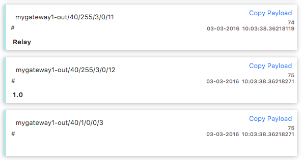
The question is which of those topics should I be sending my on off commands to? I also want to understand the messages.
The 1st message from the node is just stating 'node' which I assume just confirms that node is there?
The second message just states '1.0' I assume this is the sketch version?
The third message is blank but I assume this should show the state of the relay ie either 0 or 1. Is that correct?
So based in that logic I have been sending my commands to the last tooic, but I also tried all the others just in case. But none will switch the relay.
Is this correct
-
n the incomingMessage function of the relay sketch there are several Serial.print statements that will be output to the serial monitor if a new message is received from the gateway.
You have tried hek's code and that works by switching the relay on and off then the hardware hookup of the relay should be ok.
Do you see the messages from the lines
Serial.print("Incoming change for sensor:"); Serial.print(message.sensor); Serial.print(", New status: "); Serial.println(message.getBool()); -
Hi @Boots33 This is starting to drive my a little crazy, I've managed to get lots of other mysenors working without this much trouble!! I feel like a bit of a failure at this point.
Yes I tried @hek simple sketch which makes the relay switch on and off contiunously, so it must be wired up correctly.
I'm not sure what the debug lines should look like?? The following appears in the serial monitor as soon as I switch on the nano
send: 40-40-0-0 s=255,c=3,t=15,pt=2,l=2,sg=0,st=ok:0
send: 40-40-0-0 s=255,c=0,t=18,pt=0,l=5,sg=0,st=fail:1.5.4
send: 40-40-0-0 s=255,c=3,t=6,pt=1,l=1,sg=0,st=ok:0
repeater started, id=40, parent=0, distance=1
send: 40-40-0-0 s=255,c=3,t=11,pt=0,l=5,sg=0,st=ok:Relay
send: 40-40-0-0 s=255,c=3,t=12,pt=0,l=3,sg=0,st=ok:1.0
send: 40-40-0-0 s=1,c=0,t=3,pt=0,l=0,sg=0,st=ok:
I was expecting the last send to have a something after the ok: or is that normal?
I'm not clear as to which topic I need to send the commands to, which I think is part of the problem?
Here's the code I have been using in my openhab items file which defiantly sends the commands to the broker as I see them appear in MQTT fx,
Switch Testlight "Test switch" (Bedroom) {mqtt=">[matt_broker:mygateway1-in/40/1/0/0/3:command:ON:1],>[matt_broker:mygateway1-in/40/1/0/0/3:command:OFF:0]"}but as to which topic they need to go to I'm still stuck. Although I have tried all the ones that appear in the broker and none of them will switch the relay. Am I missing something really obvious here!!
-
Hi @Boots33 This is starting to drive my a little crazy, I've managed to get lots of other mysenors working without this much trouble!! I feel like a bit of a failure at this point.
Yes I tried @hek simple sketch which makes the relay switch on and off contiunously, so it must be wired up correctly.
I'm not sure what the debug lines should look like?? The following appears in the serial monitor as soon as I switch on the nano
send: 40-40-0-0 s=255,c=3,t=15,pt=2,l=2,sg=0,st=ok:0
send: 40-40-0-0 s=255,c=0,t=18,pt=0,l=5,sg=0,st=fail:1.5.4
send: 40-40-0-0 s=255,c=3,t=6,pt=1,l=1,sg=0,st=ok:0
repeater started, id=40, parent=0, distance=1
send: 40-40-0-0 s=255,c=3,t=11,pt=0,l=5,sg=0,st=ok:Relay
send: 40-40-0-0 s=255,c=3,t=12,pt=0,l=3,sg=0,st=ok:1.0
send: 40-40-0-0 s=1,c=0,t=3,pt=0,l=0,sg=0,st=ok:
I was expecting the last send to have a something after the ok: or is that normal?
I'm not clear as to which topic I need to send the commands to, which I think is part of the problem?
Here's the code I have been using in my openhab items file which defiantly sends the commands to the broker as I see them appear in MQTT fx,
Switch Testlight "Test switch" (Bedroom) {mqtt=">[matt_broker:mygateway1-in/40/1/0/0/3:command:ON:1],>[matt_broker:mygateway1-in/40/1/0/0/3:command:OFF:0]"}but as to which topic they need to go to I'm still stuck. Although I have tried all the ones that appear in the broker and none of them will switch the relay. Am I missing something really obvious here!!
Hi!
I can see two problems.
You have one failed message in the log, so radio comm is not perfect.
Your topic structure is wrong.
For the dev branch mqtt topic structure is like this:
Prefix/node_id/child_id/message_type/ack/message_subtypeSo you want to use the message type set which is a 1. And for a actuator with type S_LIGHT and V_LIGHT subtype will be a 2 when doing a set message.
If node is 40 and child is 1, like in your example, topic structure is:
prefix/40/1/1/0/2 -
@martinhjelmare Thanks for your input, I have finally got the relay working based on your example :-)
Thanks for your explanation of the topic structure? I'm still struggling to understand the mqtt topic structre is there somewhere I can read a good explanation?
I can see how you work out the prefix node_id and child_id but how do I know or work out message type ack and message_subtype?
I just want to understand this better for future reference.
Switch mqttsw1 "Test Switch" (Bedroom) {mqtt=">[matt_broker:mygateway1-in/40/1/1/0/2:command:ON:1],>[matt_broker:mygateway1-in/40/1/1/0/2:command:OFF:0]"} -
@martinhjelmare Thanks for your input, I have finally got the relay working based on your example :-)
Thanks for your explanation of the topic structure? I'm still struggling to understand the mqtt topic structre is there somewhere I can read a good explanation?
I can see how you work out the prefix node_id and child_id but how do I know or work out message type ack and message_subtype?
I just want to understand this better for future reference.
Switch mqttsw1 "Test Switch" (Bedroom) {mqtt=">[matt_broker:mygateway1-in/40/1/1/0/2:command:ON:1],>[matt_broker:mygateway1-in/40/1/1/0/2:command:OFF:0]"}For the mqtt client on the dev branch there is a sticky guide in the forum:
http://forum.mysensors.org/topic/2352/guide-setting-up-and-testing-mqtt-client-gatewayFor the message types etc see the serial API. It's my number one visited page on the mysensors web. Although I'm starting to know it by heart now.:wink:
Hello! It looks like you're interested in this conversation, but you don't have an account yet.
Getting fed up of having to scroll through the same posts each visit? When you register for an account, you'll always come back to exactly where you were before, and choose to be notified of new replies (either via email, or push notification). You'll also be able to save bookmarks and upvote posts to show your appreciation to other community members.
With your input, this post could be even better 💗
Register Login