Fire pit RGB striplight controller
-
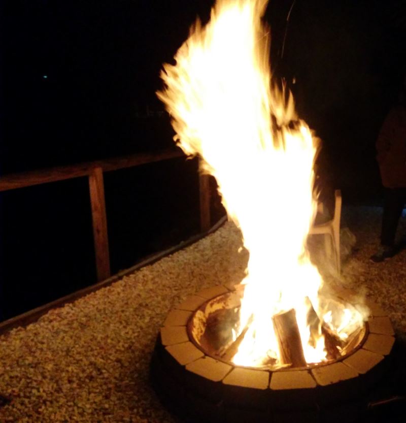
I built a fire pit in our back yard using an old crusher mantle.

I wanted the area to look nice so added some led strip lighting to the underside of the railings
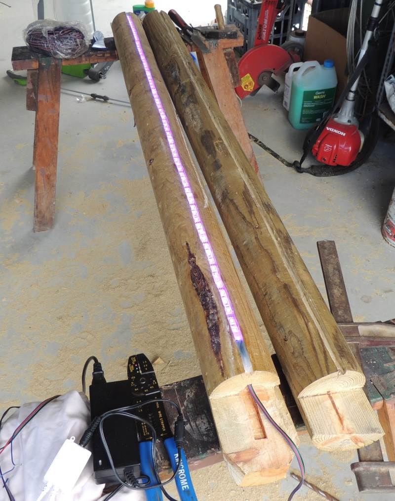
There are some clear led garden lights as well. Together the make a very inviting place to entertain friends.
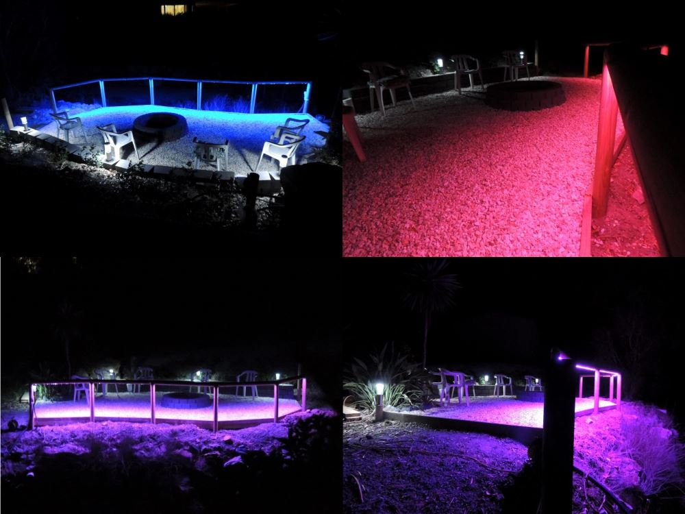
and a very comfy place to relax on the cooler nights
So now it is time to bring the lighting under Mysensors control. This is a work in progress and I will post wiring etc as I go but thought i would throw the sketch up for a start.
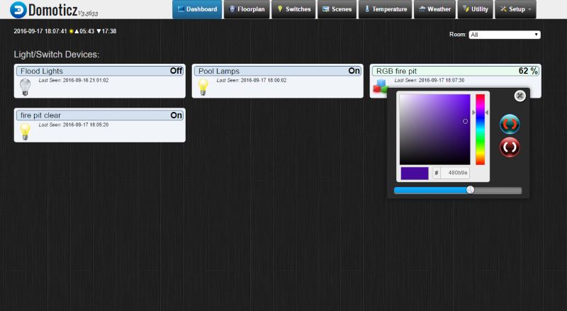
This node will control the RGB strip as well as separate switch for the white garden lights. In Domoticz the RGB controller looks like this. It can be used to set the brightness and colour of the strip. I will be using mosfet's to control all of the lights.
The current sketch is working well on a breadboard prototype using a single RGB led . I will probably add some form of colour cycling as well as I progress.
/* RGB LED Node for 12v common anode rgb strip, Also has a standard on/off switch to control an extra set of garden lights PWM pins (3, 5, 6, 9, 10, or 11). */ // Enable debug prints to serial monitor #define MY_DEBUG #define MY_NODE_ID 200 // I use 200 for my test nodes I will remove this line when it is installed // Enable and select radio type attached #define MY_RADIO_NRF24 #include <SPI.h> #include <MySensors.h> #define RGB_CHILD_ID 1 // the rbg device includes a dimmer and on/off switch as well #define CHILD_ID_LIGHT_B 2 const int controlPinA = 7; //used to turn of rgb Power pin const int controlPinB = 8; //used to switch off other garden lights const int redPin = 3; //pin used to switch the red mosfet const int greenPin = 5; //pin used to switch the green mosfet const int bluePin = 6; //pin used to switch the blue mosfet long RGB_values[3] = {0,0,0}; //array used to hold the three rgb colours int dimSet = 0; // holder for the current dimmer setting // int dimHolder = 0; void setup() { pinMode(controlPinA, OUTPUT); //| pinMode(controlPinB, OUTPUT); //| pinMode(redPin, OUTPUT); //| setup pins as outputs pinMode(greenPin, OUTPUT); //| pinMode(bluePin, OUTPUT); //| setColor(0,0,0); // make sure lights are off when first booted } void presentation() { // Present sketch (name, version) sendSketchInfo("RGB Node", "1.0"); // Register sensors (id, type, description, ack back) present(RGB_CHILD_ID, S_RGB_LIGHT,"Firepit RGB Control"); present(CHILD_ID_LIGHT_B, S_LIGHT,"Firepit Lights"); } void loop() { //nothing needed in here } /*-----------------Start of functions---------------------*/ /*----------- function to display LED colour as well as set brightness------------*/ void setColor(int red, int green, int blue){ if (dimSet != 0){ analogWrite(redPin, round(red*dimSet/100)); //| analogWrite(greenPin, round(green*dimSet/100)); //| change the three rgb colours and adjust brightness analogWrite(bluePin, round(blue*dimSet/100)); //| } else{ // if dimmer setting is 0 then set all colours to 0 analogWrite(redPin, dimSet); analogWrite(greenPin, dimSet); analogWrite(bluePin, dimSet); } #ifdef MY_DEBUG //Print debug info if enabled Serial.print("RED = "); Serial.println(red); Serial.print("BLUE = "); Serial.println(blue); Serial.print("GREEN = "); Serial.println(green); #endif } void receive(const MyMessage &message) { if (message.type==V_RGB) { //check for RGB message type /* process the RGB hex code */ String rgbHexString = message.getString(); //Load the hex color code into a string long number = (long) strtol( &rgbHexString[0], NULL, 16); RGB_values[0] = number >> 16; RGB_values[1] = number >> 8 & 0xFF; RGB_values[2] = number & 0xFF; setColor(RGB_values[0],RGB_values[1],RGB_values[2]); // call the setColor function to update the LED's #ifdef MY_DEBUG //Print debug info if enabled Serial.print("HEX RGB " ); Serial.println(rgbHexString); Serial.print("long number " ); Serial.println(number); #endif } if (message.type==V_DIMMER) { //check for dimmer message type dimSet = message.getInt(); // Load the dimmer setting into dimSet setColor(RGB_values[0],RGB_values[1],RGB_values[2]); // call the setColor function to update the LED's. new dimmer setting #ifdef MY_DEBUG //Print debug info if enabled Serial.print("dimmer setting " ); Serial.println(dimSet); #endif } if (message.type==V_LIGHT) { //check for incoming light switch message type switch (message.sensor) { case 1: //message is for sensor 1 (RGB switch) digitalWrite(controlPinA, message.getBool() ? 1 : 0); break; case 2: //message is for sensor 2 (garden lights) digitalWrite(controlPinB, message.getBool() ? 1 : 0); break; } #ifdef MY_DEBUG Serial.print("Incoming change for sensor:"); Serial.println(message.sensor); Serial.print("Light switch setting " ); Serial.println(message.getBool()); #endif } } -
wow. that looks great!!
-
Found a nice routine for the colour cycling, it gives a very smooth fade between colours.
Sketch below
/* RGB LED Node for 12v common anode rgb strip, Also has a standard on/off switch to control an extra set of garden lights and a standard on/off switch to select colour cycling PWM pins (3, 5, 6, 9, 10, or 11). colour cycling routine from https://gist.github.com/jamesotron/766994 */ // Enable debug prints to serial monitor #define MY_DEBUG #define MY_NODE_ID 200 // I use 200 for my test nodes I will remove this line when it is installed // Enable and select radio type attached #define MY_RADIO_NRF24 #include <SPI.h> #include <MySensors.h> #define RGB_CHILD_ID 1 // the rbg device includes a dimmer and on/off switch as well #define CHILD_ID_LIGHT_B 2 #define CYCLE_SWITCH_ID 3 const int controlPinA = 7; //used to turn on/off rgb Power pin const int controlPinB = 8; //used to switch on/off other garden lights const int redPin = 3; //pin used to switch the red mosfet const int greenPin = 5; //pin used to switch the green mosfet const int bluePin = 6; //pin used to switch the blue mosfet long RGB_values[3] = {0,0,0}; //array used to hold the three rgb colours int dimSet = 0; // holder for the current dimmer setting int cycleSpeed = 20; // this sets the speed of the colour cycling bool cycleState = 0; // used to check if colour cycling is turned on // int dimHolder = 0; MyMessage msg(CYCLE_SWITCH_ID, V_STATUS); void setup() { pinMode(controlPinA, OUTPUT); //| pinMode(controlPinB, OUTPUT); //| pinMode(redPin, OUTPUT); //| setup pins as outputs pinMode(greenPin, OUTPUT); //| pinMode(bluePin, OUTPUT); //| setColor(0,0,0); // make sure lights are off when first booted } void presentation() { // Present sketch (name, version) sendSketchInfo("RGB Node", "1.0"); // Register sensors (id, type, description, ack back) present(RGB_CHILD_ID, S_RGB_LIGHT,"Firepit RGB Control"); present(CHILD_ID_LIGHT_B, S_LIGHT,"Firepit Garden Lights"); present(CYCLE_SWITCH_ID, S_LIGHT,"Cycle Switch"); } void loop() { if (cycleState == 1){ // check to see is colour cycling is turned on cyclecolor(); } } /*-----------------Start of functions---------------------*/ /*----------- function to display LED colour as well as set brightness------------*/ void setColor(int red, int green, int blue){ if (dimSet != 0){ analogWrite(redPin, round(red*dimSet/100)); //| analogWrite(greenPin, round(green*dimSet/100)); //| change the three rgb colours and adjust brightness analogWrite(bluePin, round(blue*dimSet/100)); //| } else{ // if dimmer setting is 0 then set all colours to 0 analogWrite(redPin, dimSet); analogWrite(greenPin, dimSet); analogWrite(bluePin, dimSet); } #ifdef MY_DEBUG //Print debug info if enabled Serial.print("RED = "); Serial.println(red); Serial.print("BLUE = "); Serial.println(blue); Serial.print("GREEN = "); Serial.println(green); #endif } /*------------------process incoming messages--------------------*/ void receive(const MyMessage &message) { if (message.type==V_RGB) { //check for RGB message type /* process the RGB hex code */ String rgbHexString = message.getString(); //Load the hex color code into a string long number = (long) strtol( &rgbHexString[0], NULL, 16); RGB_values[0] = number >> 16; RGB_values[1] = number >> 8 & 0xFF; RGB_values[2] = number & 0xFF; setColor(RGB_values[0],RGB_values[1],RGB_values[2]); // call the setColor function to update the LED's #ifdef MY_DEBUG //Print debug info if enabled Serial.print("HEX RGB " ); Serial.println(rgbHexString); Serial.print("long number " ); Serial.println(number); #endif } if (message.type==V_DIMMER) { //check for dimmer message type if(cycleState == 1){ // new incoming colour change, turn off cycling if it is on send(msg.set(false)); cycleState = 0; } dimSet = message.getInt(); // Load the dimmer setting into dimSet setColor(RGB_values[0],RGB_values[1],RGB_values[2]); // call the setColor function to update the LED's. new dimmer setting #ifdef MY_DEBUG //Print debug info if enabled Serial.print("dimmer setting " ); Serial.println(dimSet); #endif } if (message.type==V_LIGHT) { //check for incoming light switch message type switch (message.sensor) { case 1: //message is for sensor 1 (RGB switch) digitalWrite(controlPinA, message.getBool() ? 1 : 0); break; case 2: //message is for sensor 2 (garden lights) digitalWrite(controlPinB, message.getBool() ? 1 : 0); break; case 3: // message is for sensor 3 (colour cycle switch) cycleState = message.getBool() ? 1: 0; break; } #ifdef MY_DEBUG //print some degug info if enabled Serial.print("Incoming change for sensor:"); Serial.println(message.sensor); Serial.print("Light switch setting " ); Serial.println(message.getBool()); #endif } } /*---------------function to cycle colours-----------------------*/ void cyclecolor(){ /*Start off with red*/ RGB_values[0] = 255; RGB_values[1] = 0; RGB_values[2] = 0; /* Choose the colours to increment and decrement.*/ for (int decColour = 0; decColour < 3; decColour += 1) { int incColour = decColour == 2 ? 0 : decColour + 1; /* cross-fade the two colours*/ for(int i = 0; i < 255; i += 1) { RGB_values[decColour] -= 1; RGB_values[incColour] += 1; analogWrite(redPin, RGB_values[0]); analogWrite(greenPin, RGB_values[1]); analogWrite(bluePin, RGB_values[2]); if (cycleState == 0){ // If colour cycling is turned off break out to main loop break; } wait(cycleSpeed); // this controls the speed of the colour cycling } } } -
@Boots33
Looks awesome!
I have a question. I took your sketch and it works great, but is it possible not to use the separate V_LIGHT to turn it on/off? What I mean is that I don't want to put a rele or a MOSFET to control the RGB power but to start/stop dimming by using just one RGB icon in domoticz. And turn it off by either setting dimmer value to 0 or pressing the off button in domoticz RGB switch. Is it possible? -
@Boots33
Looks awesome!
I have a question. I took your sketch and it works great, but is it possible not to use the separate V_LIGHT to turn it on/off? What I mean is that I don't want to put a rele or a MOSFET to control the RGB power but to start/stop dimming by using just one RGB icon in domoticz. And turn it off by either setting dimmer value to 0 or pressing the off button in domoticz RGB switch. Is it possible?Hi @Tigroenot The reason i used the xtra mosfet was mainly so the leds would just resume with whatever they were previously set to when the rgb switch was turned back on and also as this node is powered all the time wanted to make sure it turned off completely. I can see no reason why you could not do away with the IRF4905 and just set the three channels to 0.
You would need to save the current state to the arduino eeprom if you wanted to have it resume with the same colour etc when the switch is turned back on.In fact part of the code does set all the channels to 0 already if the dim level is set to 0.
You can see below that if dimSet = 0 then the else statement is executed , setting all the channels to 0
void setColor(int red, int green, int blue){
if (dimSet != 0){
 analogWrite(redPin, round(red*dimSet/100));          //|
 analogWrite(greenPin, round(green*dimSet/100));      //| change the three rgb colours and adjust brightness
 analogWrite(bluePin, round(blue*dimSet/100));        //|
}
else{                                                // if dimmer setting is 0 then set all colours to 0
  analogWrite(redPin, dimSet);
  analogWrite(greenPin, dimSet);
  analogWrite(bluePin, dimSet);
}
You would also need to change the code where it reacts to the incoming message from the RGB switch.
Instead of
case 1:                                                     //message is for sensor 1 (RGB switch)
        digitalWrite(controlPinA, message.getBool() ? 1 : 0);     // change state of RGB power switch
        break;
you would need to try something like the code below. It is untested so you may need to tweak it a bit.
case 1: //message is for sensor 1 (RGB switch) // digitalWrite(controlPinA, message.getBool() ? 1 : 0); // change state of RGB power switch if (message.getBool()== 0){ setColor(0,0,0); // turn lights off cycleState = 0; // turn off colour cycling } else{ setColor(200,0,0); // turn lights red when first turned on } break; -
I have been distracted from this project with other things but intend to finish it off soon. I am posting the current wiring diagram which I have tested with a 5m RGB strip. I can confirm the mosfets do not heat up at all, even without heatsinks so all looks good.
I am thinking of changing the clear garden lights from a mosfet to a relay as they are powered by 12AC so will need to rectify that or switch the AC with a relay. still a work in progress
The circuit
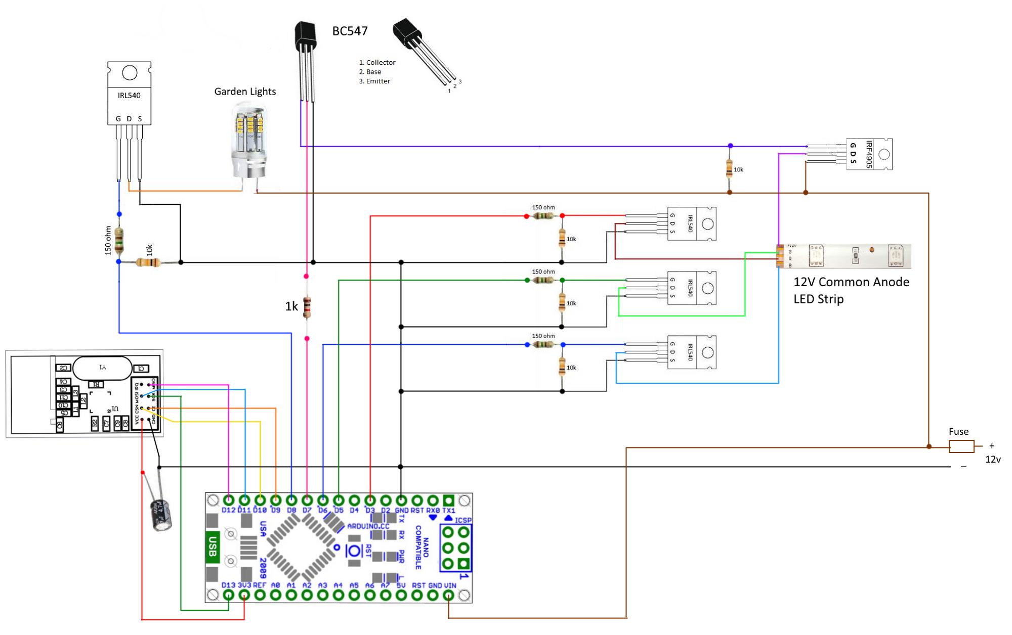
-
So I decided to leave the garden lights running on 12v AC as this may offer less voltage drop and wire corrosion than if I were to switch to DC.
I had a double relay module on hand so have added an extra switch to the sketch. this node now controls the RGB Strip as well as the two relays. The relay modules need to be switched high to turn off so I have also modified the sketch to suit.
I think the sketch and diagram below will be the ones I use.
/*
RGB LED Node for 12v common anode rgb strip,
Also has two standard on/off switches to control  extra  garden lights
and a standard on/off switch to select colour cycling
PWM pins (3, 5, 6, 9, 10, or 11).
colour cycling routine from https://gist.github.com/jamesotron/766994

*/

// Enable debug prints to serial monitor
#define MY_DEBUG
#define MY_NODE_ID 200  // I use 200 for my test nodes I will remove this line when it is installed
// Enable and select radio type attached
#define MY_RADIO_NRF24

#include <SPI.h>
#include <MySensors.h>
#define RGB_CHILD_ID 1                // the rbg device includes a dimmer and on/off switch as well
#define CHILD_ID_LIGHT_1 2            //garden lights 1
#define CYCLE_SWITCH_ID 3             // colour cycle switch
#define CHILD_ID_LIGHT_2 4            // garden lights 2

const int controlPinA = 7;                          //pin used to turn on/off rgb Power
const int controlPin1 = 8;                          //pin used to switch on/off  garden lights 1
const int controlPin2 = 4;                          //pin used to switch on/off garden lights 2
const int redPin = 3;                               //pin used to switch the red mosfet
const int greenPin = 5;                             //pin used to switch the green mosfet
const int bluePin = 6;                              //pin used to switch the blue mosfet
long RGB_values[3] = {0,0,0};                       //array used to hold the three rgb colours
int dimSet = 0;                                     // holder for the current dimmer setting
int cycleSpeed = 20;                                // this sets the speed of the colour cycling
bool cycleState = 0;                                // used to check if colour cycling is turned on. 0 means it will be off when node starts up
bool onceOnly = 0;                                  //used to excecute some code once at startup

MyMessage msg(CYCLE_SWITCH_ID, V_STATUS);
MyMessage rgbmsgA(RGB_CHILD_ID, V_PERCENTAGE);
MyMessage gardenlightmsg1(CHILD_ID_LIGHT_1, V_STATUS);
MyMessage gardenlightmsg2(CHILD_ID_LIGHT_2, V_STATUS);

void setup()
{
pinMode(controlPinA, OUTPUT);    //|
pinMode(controlPin1, OUTPUT);    //|
pinMode(controlPin2, OUTPUT);    //|
pinMode(redPin, OUTPUT);         //| setup pins as outputs
pinMode(greenPin, OUTPUT);       //|
pinMode(bluePin, OUTPUT);        //|
setColor(0,0,0);                 // make sure RGB lights are off at startup
digitalWrite(controlPin1,HIGH);   // make sure garden lights are off at startup. relay module swithces High to turn off
digitalWrite(controlPin2,HIGH);   // make sure garden lights are off at startup. relay module swithces High to turn off
}

void presentation()  {
// Present sketch (name, version)
sendSketchInfo("RGB Node", "0.1");

// Register sensors (id, type, description, ack back)
 present(RGB_CHILD_ID, S_RGB_LIGHT,"Firepit RGB Control");
 present(CHILD_ID_LIGHT_1, S_LIGHT," Garden Lights 1");
 present(CYCLE_SWITCH_ID, S_LIGHT,"RGB Cycle Switch");
 present(CHILD_ID_LIGHT_2, S_LIGHT," Garden Lights 2");
}

void loop()
{
if (onceOnly == 0){                     // this code only exectutes once at startup to make sure controller knows switch settings are off
 send(msg.set(false));                // send message to switch off colour cycling
 send(rgbmsgA.set(0));                // send message to switch off RGB lights
 send(gardenlightmsg1.set(false));    // send message to switch off garden lights relay 1
 send(gardenlightmsg2.set(false));    // send message to switch off garden lights relay 2
 onceOnly = 1;
}
if (cycleState == 1){  // check to see is colour cycling is turned on
cyclecolor();
}
}

/*-----------------Start of functions---------------------*/


/*----------- function to display LED colour as well as set brightness------------*/
void setColor(int red, int green, int blue){
if (dimSet != 0){
analogWrite(redPin, round(red*dimSet/100));          //|
analogWrite(greenPin, round(green*dimSet/100));      //| change the three rgb colours and adjust brightness
analogWrite(bluePin, round(blue*dimSet/100));        //|
}
else{                                                // if dimmer setting is 0 then set all colours to 0
analogWrite(redPin, dimSet);
analogWrite(greenPin, dimSet);
analogWrite(bluePin, dimSet);
}
#ifdef MY_DEBUG            //Print debug info if enabled
Serial.print("RED = ");
Serial.println(red);
Serial.print("BLUE = ");
Serial.println(blue);
Serial.print("GREEN = ");
Serial.println(green);
#endif
}


/*------------------process incoming messages--------------------*/
void receive(const MyMessage &message) {
switch (message.type) {
case V_LIGHT:                                                //message is for a light switch (2)
  #ifdef MY_DEBUG                                            //print some degug info if enabled
    Serial.print("Incoming change for sensor:");
    Serial.println(message.sensor);
    Serial.print("Light switch setting " );
    Serial.println(message.getBool());
  #endif
   switch (message.sensor) {
    case 1:                                                     //message is for sensor 1 (RGB switch)
      digitalWrite(controlPinA, message.getBool() ? 1 : 0);     // change state of RGB power switch
      break;
    case 2:                                                     //message is for sensor 2 (garden lights switch 1)
      digitalWrite(controlPin1, message.getBool() ? 0 : 1);     //change state of garden light switch
      break;
    case 3:                                                     // message is for sensor 3 (colour cycle switch)
      cycleState = message.getBool() ? 1: 0;                    // change state of colour cycle
      break;
    case 4:                                                     //message is for sensor 4 (garden lights switch 2)
      digitalWrite(controlPin2, message.getBool() ? 0 : 1);     //change state of garden light switch
      break;
   }
   break;
case V_PERCENTAGE:                                                  //check for dimmer message type (3)
   if(cycleState == 1){                                         // new incoming colour change, turn off cycling if it is on
   send(msg.set(false));
   cycleState = 0;
   }
  dimSet = message.getInt();                                        // Load the dimmer setting into dimSet
  setColor(RGB_values[0],RGB_values[1],RGB_values[2]);              // call the setColor function to update the LED's. new dimmer setting
  #ifdef MY_DEBUG                                                   //Print debug info if enabled
   Serial.print("dimmer setting " );
   Serial.println(dimSet);
  #endif
  break;
case V_RGB:                                                       //check for RGB message type (40)
    /*   process the RGB hex code    */
  String rgbHexString = message.getString();                      //Load the hex color code into a string
  long number = (long) strtol( &rgbHexString[0], NULL, 16);
  RGB_values[0] = number >> 16;
  RGB_values[1] = number >> 8 & 0xFF;
  RGB_values[2] = number & 0xFF;
  setColor(RGB_values[0],RGB_values[1],RGB_values[2]);            // call the setColor function to update the LED's
#ifdef MY_DEBUG                                                   //Print debug info if enabled
   Serial.print("HEX RGB " );
   Serial.println(rgbHexString);
   Serial.print("long number " );
   Serial.println(number);
#endif
}
}

/*---------------function to cycle colours-----------------------*/
void cyclecolor(){

/*Start off with red*/
RGB_values[0] = 255;
RGB_values[1] = 0;
RGB_values[2] = 0;
/* Choose the colours to increment and decrement.*/
for (int decColour = 0; decColour < 3; decColour += 1) {
  int incColour = decColour == 2 ? 0 : decColour + 1;

/* cross-fade the two colours*/
for(int i = 0; i < 255; i += 1) {
 RGB_values[decColour] -= 1;
 RGB_values[incColour] += 1;
 analogWrite(redPin, RGB_values[0]);
 analogWrite(greenPin, RGB_values[1]);
 analogWrite(bluePin, RGB_values[2]);
 if (cycleState == 0){                 // If colour cycling is turned off break out to main loop
   break;
 }
 wait(cycleSpeed);   // this controls the speed of the colour cycling
}
}
}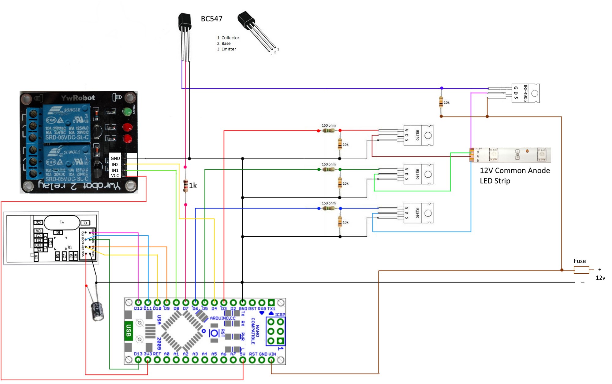
-
Be careful powering the Nano from 12V - there are reports elsewhere on this forum of some versions getting fried at this voltage!
Thanks @MikeF as you say they can get quite hot when run at the higher end of their voltage tolerance. .
I have never had a nano fail on me at 12v though and as this is an outside node located where it can do no harm if it fails I am happy to avoid the extra voltage regulator.If it was a node to be situated inside the house then I always try and keep to 9v or less just to make sure it all runs cool.
-
Thanks @MikeF as you say they can get quite hot when run at the higher end of their voltage tolerance. .
I have never had a nano fail on me at 12v though and as this is an outside node located where it can do no harm if it fails I am happy to avoid the extra voltage regulator.If it was a node to be situated inside the house then I always try and keep to 9v or less just to make sure it all runs cool.
I've fried a couple pro mini's and a nano running 12v to the vin/raw... actually in one case it might have been up to 15v .... oops.
But I've since learned my lesson.... I now use a Linear Voltage Regulator between the source and the arduino for all my builds that have a higher voltage power source (i.e.: builds that run lights). Typically a L7805CV or L7809CV or L7810CV (or other) depending on the voltage of my source and what I want to send to the arduino.
Here is an example L7809CV from AliExpress
Hello! It looks like you're interested in this conversation, but you don't have an account yet.
Getting fed up of having to scroll through the same posts each visit? When you register for an account, you'll always come back to exactly where you were before, and choose to be notified of new replies (either via email, or push notification). You'll also be able to save bookmarks and upvote posts to show your appreciation to other community members.
With your input, this post could be even better 💗
Register Login