Ethernet gateway shows up on vera , but doens't want to include devices
-
@blacey
Im not sure if we are on the same page. I already have a hookup with my vera via USB and that is working fine. Separately, I was trying to add this Ethernet setup. I can get the ethernet to connect, or so I think but the inclusion mode is just totally not working. You can see the logs from the arduino and also the uploaded code. I have tried the different versions of the library and still nothing. Again, everything works fine with my current setup with the vera and the USB connection but not this new setup (Ethernet to the vera)./** * The MySensors Arduino library handles the wireless radio link and protocol * between your home built sensors/actuators and HA controller of choice. * The sensors forms a self healing radio network with optional repeaters. Each * repeater and gateway builds a routing tables in EEPROM which keeps track of the * network topology allowing messages to be routed to nodes. * * Created by Henrik Ekblad <henrik.ekblad@mysensors.org> * Copyright (C) 2013-2015 Sensnology AB * Full contributor list: https://github.com/mysensors/Arduino/graphs/contributors * * Documentation: http://www.mysensors.org * Support Forum: http://forum.mysensors.org * * This program is free software; you can redistribute it and/or * modify it under the terms of the GNU General Public License * version 2 as published by the Free Software Foundation. * ******************************* * * REVISION HISTORY * Version 1.0 - Henrik EKblad * Contribution by a-lurker and Anticimex, * Contribution by Norbert Truchsess <norbert.truchsess@t-online.de> * Contribution by Tomas Hozza <thozza@gmail.com> * * * DESCRIPTION * The EthernetGateway sends data received from sensors to the ethernet link. * The gateway also accepts input on ethernet interface, which is then sent out to the radio network. * * The GW code is designed for Arduino 328p / 16MHz. ATmega168 does not have enough memory to run this program. * * LED purposes: * - To use the feature, uncomment MY_DEFAULT_xxx_LED_PIN in the sketch below * - RX (green) - blink fast on radio message recieved. In inclusion mode will blink fast only on presentation recieved * - TX (yellow) - blink fast on radio message transmitted. In inclusion mode will blink slowly * - ERR (red) - fast blink on error during transmission error or recieve crc error * * See http://www.mysensors.org/build/ethernet_gateway for wiring instructions. * */ // Enable debug prints to serial monitor #define MY_DEBUG // Enable and select radio type attached #define MY_RADIO_NRF24 //#define MY_RADIO_RFM69 // Enable gateway ethernet module type #define MY_GATEWAY_W5100 // W5100 Ethernet module SPI enable (optional if using a shield/module that manages SPI_EN signal) //#define MY_W5100_SPI_EN 4 // Enable Soft SPI for NRF radio (note different radio wiring is required) // The W5100 ethernet module seems to have a hard time co-operate with // radio on the same spi bus. #if !defined(MY_W5100_SPI_EN) && !defined(ARDUINO_ARCH_SAMD) #define MY_SOFTSPI #define MY_SOFT_SPI_SCK_PIN 14 #define MY_SOFT_SPI_MISO_PIN 16 #define MY_SOFT_SPI_MOSI_PIN 15 #endif // When W5100 is connected we have to move CE/CSN pins for NRF radio #ifndef MY_RF24_CE_PIN #define MY_RF24_CE_PIN 5 #endif #ifndef MY_RF24_CS_PIN #define MY_RF24_CS_PIN 6 #endif // Enable to UDP //#define MY_USE_UDP #define MY_IP_ADDRESS 192,168,50,155 // If this is disabled, DHCP is used to retrieve address // Renewal period if using DHCP //#define MY_IP_RENEWAL_INTERVAL 60000 // The port to keep open on node server mode / or port to contact in client mode #define MY_PORT 5003 // Controller ip address. Enables client mode (default is "server" mode). // Also enable this if MY_USE_UDP is used and you want sensor data sent somewhere. //#define MY_CONTROLLER_IP_ADDRESS 192, 168, 178, 254 // The MAC address can be anything you want but should be unique on your network. // Newer boards have a MAC address printed on the underside of the PCB, which you can (optionally) use. // Note that most of the Ardunio examples use "DEAD BEEF FEED" for the MAC address. #define MY_MAC_ADDRESS 0xDE, 0xAD, 0xBE, 0xEF, 0xFE, 0xED // Enable inclusion mode #define MY_INCLUSION_MODE_FEATURE // Enable Inclusion mode button on gateway //#define MY_INCLUSION_BUTTON_FEATURE // Set inclusion mode duration (in seconds) #define MY_INCLUSION_MODE_DURATION 60 // Digital pin used for inclusion mode button //#define MY_INCLUSION_MODE_BUTTON_PIN 3 // Set blinking period #define MY_DEFAULT_LED_BLINK_PERIOD 300 // Flash leds on rx/tx/err // Uncomment to override default HW configurations //#define MY_DEFAULT_ERR_LED_PIN 7 // Error led pin //#define MY_DEFAULT_RX_LED_PIN 8 // Receive led pin //#define MY_DEFAULT_TX_LED_PIN 9 // Transmit led pin #if defined(MY_USE_UDP) #include <EthernetUdp.h> #endif #include <Ethernet.h> #include <MySensors.h> void setup() { } void loop() { }This is what I get out of the serial monitor. Everything seems to be normal. I even think that it acts like a repeater for other devices but it just wont all me to include other devices.
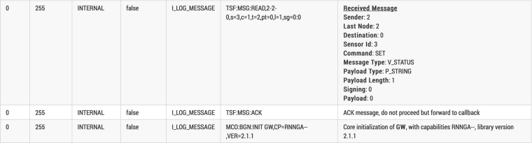
0;255;3;0;9;MCO:BGN:INIT GW,CP=RNNGA--,VER=2.1.1 0;255;3;0;9;TSM:INIT 0;255;3;0;9;TSF:WUR:MS=0 0;255;3;0;9;TSM:INIT:TSP OK 0;255;3;0;9;TSM:INIT:GW MODE 0;255;3;0;9;TSM:READY:ID=0,PAR=0,DIS=0 0;255;3;0;9;MCO:REG:NOT NEEDED IP: 192.168.50.155 0;255;3;0;9;MCO:BGN:STP 0;255;3;0;9;MCO:BGN:INIT OK,TSP=1 0;255;3;0;9;Eth: connect 0;255;3;0;9;MCO:BGN:INIT GW,CP=RNNGA--,VER=2.1.1 0;255;3;0;9;TSM:INIT 0;255;3;0;9;TSF:WUR:MS=0 0;255;3;0;9;TSM:INIT:TSP OK 0;255;3;0;9;TSM:INIT:GW MODE 0;255;3;0;9;TSM:READY:ID=0,PAR=0,DIS=0 0;255;3;0;9;MCO:REG:NOT NEEDED IP: 192.168.50.155 0;255;3;0;9;MCO:BGN:STP 0;255;3;0;9;MCO:BGN:INIT OK,TSP=1 0;255;3;0;9;Eth: connect 0;255;3;0;9;MCO:BGN:INIT GW,CP=RNNGA--,VER=2.1.1 0;255;3;0;9;TSM:INIT 0;255;3;0;9;TSF:WUR:MS=0 0;255;3;0;9;TSM:INIT:TSP OK 0;255;3;0;9;TSM:INIT:GW MODE 0;255;3;0;9;TSM:READY:ID=0,PAR=0,DIS=0 0;255;3;0;9;MCO:REG:NOT NEEDED IP: 192.168.50.155 0;255;3;0;9;MCO:BGN:STP 0;255;3;0;9;MCO:BGN:INIT OK,TSP=1 0;255;3;0;9;TSF:MSG:READ,2-2-0,s=3,c=1,t=2,pt=0,l=1,sg=0:0 0;255;3;0;9;TSF:MSG:ACK 0;255;3;0;9;MCO:BGN:INIT GW,CP=RNNGA--,VER=2.1.1 0;255;3;0;9;TSM:INIT 0;255;3;0;9;TSF:WUR:MS=0 0;255;3;0;9;TSM:INIT:TSP OK 0;255;3;0;9;TSM:INIT:GW MODE 0;255;3;0;9;TSM:READY:ID=0,PAR=0,DIS=0 0;255;3;0;9;MCO:REG:NOT NEEDED IP: 192.168.50.155 0;255;3;0;9;MCO:BGN:STP 0;255;3;0;9;MCO:BGN:INIT OK,TSP=1 0;255;3;0;9;TSF:MSG:READ,2-2-0,s=3,c=1,t=2,pt=0,l=1,sg=0:1 0;255;3;0;9;TSF:MSG:ACK 0;255;3;0;9;MCO:BGN:INIT GW,CP=RNNGA--,VER=2.1.1 0;255;3;0;9;TSM:INIT 0;255;3;0;9;TSF:WUR:MS=0 0;255;3;0;9;TSM:INIT:TSP OK 0;255;3;0;9;TSM:INIT:GW MODE 0;255;3;0;9;TSM:READY:ID=0,PAR=0,DIS=0 0;255;3;0;9;MCO:REG:NOT NEEDED IP: 192.168.50.155 0;255;3;0;9;MCO:BGN:STP 0;255;3;0;9;MCO:BGN:INIT OK,TSP=1 0;255;3;0;9;TSF:MSG:READ,2-2-0,s=3,c=1,t=2,pt=0,l=1,sg=0:1 0;255;3;0;9;TSF:MSG:ACK 0;255;3;0;9;MCO:BGN:INIT GW,CP=RNNGA--,VER=2.1.1 0;255;3;0;9;TSM:INIT 0;255;3;0;9;TSF:WUR:MS=0 0;255;3;0;9;TSM:INIT:TSP OK 0;255;3;0;9;TSM:INIT:GW MODE 0;255;3;0;9;TSM:READY:ID=0,PAR=0,DIS=0 0;255;3;0;9;MCO:REG:NOT NEEDED IP: 192.168.50.155 0;255;3;0;9;MCO:BGN:STP 0;255;3;0;9;MCO:BGN:INIT OK,TSP=1 0;255;3;0;9;TSF:MSG:READ,2-2-0,s=3,c=1,t=2,pt=0,l=1,sg=0:0 0;255;3;0;9;TSF:MSG:ACK 0;255;3;0;9;MCO:BGN:INIT GW,CP=RNNGA--,VER=2.1.1 0;255;3;0;9;TSM:INIT 0;255;3;0;9;TSF:WUR:MS=0 0;255;3;0;9;TSM:INIT:TSP OK 0;255;3;0;9;TSM:INIT:GW MODE 0;255;3;0;9;TSM:READY:ID=0,PAR=0,DIS=0 0;255;3;0;9;MCO:REG:NOT NEEDED IP: 192.168.50.155 0;255;3;0;9;MCO:BGN:STP 0;255;3;0;9;MCO:BGN:INIT OK,TSP=1 0;255;3;0;9;Eth: connect 0;255;3;0;9;MCO:BGN:INIT GW,CP=RNNGA--,VER=2.1.1 0;255;3;0;9;TSM:INIT 0;255;3;0;9;TSF:WUR:MS=0 0;255;3;0;9;TSM:INIT:TSP OK 0;255;3;0;9;TSM:INIT:GW MODE 0;255;3;0;9;TSM:READY:ID=0,PAR=0,DIS=0 0;255;3;0;9;MCO:REG:NOT NEEDED IP: 192.168.50.155 0;255;3;0;9;MCO:BGN:STP 0;255;3;0;9;MCO:BGN:INIT OK,TSP=1 0;255;3;0;9;Eth: connect 0;255;3;0;9;MCO:BGN:INIT GW,CP=RNNGA--,VER=2.1.1 0;255;3;0;9;TSM:INIT 0;255;3;0;9;TSF:WUR:MS=0 0;255;3;0;9;TSM:INIT:TSP OK 0;255;3;0;9;TSM:INIT:GW MODE 0;255;3;0;9;TSM:READY:ID=0,PAR=0,DIS=0 0;255;3;0;9;MCO:REG:NOT NEEDED IP: 192.168.50.155 0;255;3;0;9;MCO:BGN:STP 0;255;3;0;9;MCO:BGN:INIT OK,TSP=1 0;255;3;0;9;Eth: connect 0;255;3;0;9;MCO:BGN:INIT GW,CP=RNNGA--,VER=2.1.1 0;255;3;0;9;TSM:INIT 0;255;3;0;9;TSF:WUR:MS=0 0;255;3;0;9;TSM:INIT:TSP OK 0;255;3;0;9;TSM:INIT:GW MODE 0;255;3;0;9;TSM:READY:ID=0,PAR=0,DIS=0 0;255;3;0;9;MCO:REG:NOT NEEDED IP: 192.168.50.155 0;255;3;0;9;MCO:BGN:STP 0;255;3;0;9;MCO:BGN:INIT OK,TSP=1 -
@blacey
Im not sure if we are on the same page. I already have a hookup with my vera via USB and that is working fine. Separately, I was trying to add this Ethernet setup. I can get the ethernet to connect, or so I think but the inclusion mode is just totally not working. You can see the logs from the arduino and also the uploaded code. I have tried the different versions of the library and still nothing. Again, everything works fine with my current setup with the vera and the USB connection but not this new setup (Ethernet to the vera)./** * The MySensors Arduino library handles the wireless radio link and protocol * between your home built sensors/actuators and HA controller of choice. * The sensors forms a self healing radio network with optional repeaters. Each * repeater and gateway builds a routing tables in EEPROM which keeps track of the * network topology allowing messages to be routed to nodes. * * Created by Henrik Ekblad <henrik.ekblad@mysensors.org> * Copyright (C) 2013-2015 Sensnology AB * Full contributor list: https://github.com/mysensors/Arduino/graphs/contributors * * Documentation: http://www.mysensors.org * Support Forum: http://forum.mysensors.org * * This program is free software; you can redistribute it and/or * modify it under the terms of the GNU General Public License * version 2 as published by the Free Software Foundation. * ******************************* * * REVISION HISTORY * Version 1.0 - Henrik EKblad * Contribution by a-lurker and Anticimex, * Contribution by Norbert Truchsess <norbert.truchsess@t-online.de> * Contribution by Tomas Hozza <thozza@gmail.com> * * * DESCRIPTION * The EthernetGateway sends data received from sensors to the ethernet link. * The gateway also accepts input on ethernet interface, which is then sent out to the radio network. * * The GW code is designed for Arduino 328p / 16MHz. ATmega168 does not have enough memory to run this program. * * LED purposes: * - To use the feature, uncomment MY_DEFAULT_xxx_LED_PIN in the sketch below * - RX (green) - blink fast on radio message recieved. In inclusion mode will blink fast only on presentation recieved * - TX (yellow) - blink fast on radio message transmitted. In inclusion mode will blink slowly * - ERR (red) - fast blink on error during transmission error or recieve crc error * * See http://www.mysensors.org/build/ethernet_gateway for wiring instructions. * */ // Enable debug prints to serial monitor #define MY_DEBUG // Enable and select radio type attached #define MY_RADIO_NRF24 //#define MY_RADIO_RFM69 // Enable gateway ethernet module type #define MY_GATEWAY_W5100 // W5100 Ethernet module SPI enable (optional if using a shield/module that manages SPI_EN signal) //#define MY_W5100_SPI_EN 4 // Enable Soft SPI for NRF radio (note different radio wiring is required) // The W5100 ethernet module seems to have a hard time co-operate with // radio on the same spi bus. #if !defined(MY_W5100_SPI_EN) && !defined(ARDUINO_ARCH_SAMD) #define MY_SOFTSPI #define MY_SOFT_SPI_SCK_PIN 14 #define MY_SOFT_SPI_MISO_PIN 16 #define MY_SOFT_SPI_MOSI_PIN 15 #endif // When W5100 is connected we have to move CE/CSN pins for NRF radio #ifndef MY_RF24_CE_PIN #define MY_RF24_CE_PIN 5 #endif #ifndef MY_RF24_CS_PIN #define MY_RF24_CS_PIN 6 #endif // Enable to UDP //#define MY_USE_UDP #define MY_IP_ADDRESS 192,168,50,155 // If this is disabled, DHCP is used to retrieve address // Renewal period if using DHCP //#define MY_IP_RENEWAL_INTERVAL 60000 // The port to keep open on node server mode / or port to contact in client mode #define MY_PORT 5003 // Controller ip address. Enables client mode (default is "server" mode). // Also enable this if MY_USE_UDP is used and you want sensor data sent somewhere. //#define MY_CONTROLLER_IP_ADDRESS 192, 168, 178, 254 // The MAC address can be anything you want but should be unique on your network. // Newer boards have a MAC address printed on the underside of the PCB, which you can (optionally) use. // Note that most of the Ardunio examples use "DEAD BEEF FEED" for the MAC address. #define MY_MAC_ADDRESS 0xDE, 0xAD, 0xBE, 0xEF, 0xFE, 0xED // Enable inclusion mode #define MY_INCLUSION_MODE_FEATURE // Enable Inclusion mode button on gateway //#define MY_INCLUSION_BUTTON_FEATURE // Set inclusion mode duration (in seconds) #define MY_INCLUSION_MODE_DURATION 60 // Digital pin used for inclusion mode button //#define MY_INCLUSION_MODE_BUTTON_PIN 3 // Set blinking period #define MY_DEFAULT_LED_BLINK_PERIOD 300 // Flash leds on rx/tx/err // Uncomment to override default HW configurations //#define MY_DEFAULT_ERR_LED_PIN 7 // Error led pin //#define MY_DEFAULT_RX_LED_PIN 8 // Receive led pin //#define MY_DEFAULT_TX_LED_PIN 9 // Transmit led pin #if defined(MY_USE_UDP) #include <EthernetUdp.h> #endif #include <Ethernet.h> #include <MySensors.h> void setup() { } void loop() { }This is what I get out of the serial monitor. Everything seems to be normal. I even think that it acts like a repeater for other devices but it just wont all me to include other devices.
0;255;3;0;9;MCO:BGN:INIT GW,CP=RNNGA--,VER=2.1.1 0;255;3;0;9;TSM:INIT 0;255;3;0;9;TSF:WUR:MS=0 0;255;3;0;9;TSM:INIT:TSP OK 0;255;3;0;9;TSM:INIT:GW MODE 0;255;3;0;9;TSM:READY:ID=0,PAR=0,DIS=0 0;255;3;0;9;MCO:REG:NOT NEEDED IP: 192.168.50.155 0;255;3;0;9;MCO:BGN:STP 0;255;3;0;9;MCO:BGN:INIT OK,TSP=1 0;255;3;0;9;Eth: connect 0;255;3;0;9;MCO:BGN:INIT GW,CP=RNNGA--,VER=2.1.1 0;255;3;0;9;TSM:INIT 0;255;3;0;9;TSF:WUR:MS=0 0;255;3;0;9;TSM:INIT:TSP OK 0;255;3;0;9;TSM:INIT:GW MODE 0;255;3;0;9;TSM:READY:ID=0,PAR=0,DIS=0 0;255;3;0;9;MCO:REG:NOT NEEDED IP: 192.168.50.155 0;255;3;0;9;MCO:BGN:STP 0;255;3;0;9;MCO:BGN:INIT OK,TSP=1 0;255;3;0;9;Eth: connect 0;255;3;0;9;MCO:BGN:INIT GW,CP=RNNGA--,VER=2.1.1 0;255;3;0;9;TSM:INIT 0;255;3;0;9;TSF:WUR:MS=0 0;255;3;0;9;TSM:INIT:TSP OK 0;255;3;0;9;TSM:INIT:GW MODE 0;255;3;0;9;TSM:READY:ID=0,PAR=0,DIS=0 0;255;3;0;9;MCO:REG:NOT NEEDED IP: 192.168.50.155 0;255;3;0;9;MCO:BGN:STP 0;255;3;0;9;MCO:BGN:INIT OK,TSP=1 0;255;3;0;9;TSF:MSG:READ,2-2-0,s=3,c=1,t=2,pt=0,l=1,sg=0:0 0;255;3;0;9;TSF:MSG:ACK 0;255;3;0;9;MCO:BGN:INIT GW,CP=RNNGA--,VER=2.1.1 0;255;3;0;9;TSM:INIT 0;255;3;0;9;TSF:WUR:MS=0 0;255;3;0;9;TSM:INIT:TSP OK 0;255;3;0;9;TSM:INIT:GW MODE 0;255;3;0;9;TSM:READY:ID=0,PAR=0,DIS=0 0;255;3;0;9;MCO:REG:NOT NEEDED IP: 192.168.50.155 0;255;3;0;9;MCO:BGN:STP 0;255;3;0;9;MCO:BGN:INIT OK,TSP=1 0;255;3;0;9;TSF:MSG:READ,2-2-0,s=3,c=1,t=2,pt=0,l=1,sg=0:1 0;255;3;0;9;TSF:MSG:ACK 0;255;3;0;9;MCO:BGN:INIT GW,CP=RNNGA--,VER=2.1.1 0;255;3;0;9;TSM:INIT 0;255;3;0;9;TSF:WUR:MS=0 0;255;3;0;9;TSM:INIT:TSP OK 0;255;3;0;9;TSM:INIT:GW MODE 0;255;3;0;9;TSM:READY:ID=0,PAR=0,DIS=0 0;255;3;0;9;MCO:REG:NOT NEEDED IP: 192.168.50.155 0;255;3;0;9;MCO:BGN:STP 0;255;3;0;9;MCO:BGN:INIT OK,TSP=1 0;255;3;0;9;TSF:MSG:READ,2-2-0,s=3,c=1,t=2,pt=0,l=1,sg=0:1 0;255;3;0;9;TSF:MSG:ACK 0;255;3;0;9;MCO:BGN:INIT GW,CP=RNNGA--,VER=2.1.1 0;255;3;0;9;TSM:INIT 0;255;3;0;9;TSF:WUR:MS=0 0;255;3;0;9;TSM:INIT:TSP OK 0;255;3;0;9;TSM:INIT:GW MODE 0;255;3;0;9;TSM:READY:ID=0,PAR=0,DIS=0 0;255;3;0;9;MCO:REG:NOT NEEDED IP: 192.168.50.155 0;255;3;0;9;MCO:BGN:STP 0;255;3;0;9;MCO:BGN:INIT OK,TSP=1 0;255;3;0;9;TSF:MSG:READ,2-2-0,s=3,c=1,t=2,pt=0,l=1,sg=0:0 0;255;3;0;9;TSF:MSG:ACK 0;255;3;0;9;MCO:BGN:INIT GW,CP=RNNGA--,VER=2.1.1 0;255;3;0;9;TSM:INIT 0;255;3;0;9;TSF:WUR:MS=0 0;255;3;0;9;TSM:INIT:TSP OK 0;255;3;0;9;TSM:INIT:GW MODE 0;255;3;0;9;TSM:READY:ID=0,PAR=0,DIS=0 0;255;3;0;9;MCO:REG:NOT NEEDED IP: 192.168.50.155 0;255;3;0;9;MCO:BGN:STP 0;255;3;0;9;MCO:BGN:INIT OK,TSP=1 0;255;3;0;9;Eth: connect 0;255;3;0;9;MCO:BGN:INIT GW,CP=RNNGA--,VER=2.1.1 0;255;3;0;9;TSM:INIT 0;255;3;0;9;TSF:WUR:MS=0 0;255;3;0;9;TSM:INIT:TSP OK 0;255;3;0;9;TSM:INIT:GW MODE 0;255;3;0;9;TSM:READY:ID=0,PAR=0,DIS=0 0;255;3;0;9;MCO:REG:NOT NEEDED IP: 192.168.50.155 0;255;3;0;9;MCO:BGN:STP 0;255;3;0;9;MCO:BGN:INIT OK,TSP=1 0;255;3;0;9;Eth: connect 0;255;3;0;9;MCO:BGN:INIT GW,CP=RNNGA--,VER=2.1.1 0;255;3;0;9;TSM:INIT 0;255;3;0;9;TSF:WUR:MS=0 0;255;3;0;9;TSM:INIT:TSP OK 0;255;3;0;9;TSM:INIT:GW MODE 0;255;3;0;9;TSM:READY:ID=0,PAR=0,DIS=0 0;255;3;0;9;MCO:REG:NOT NEEDED IP: 192.168.50.155 0;255;3;0;9;MCO:BGN:STP 0;255;3;0;9;MCO:BGN:INIT OK,TSP=1 0;255;3;0;9;Eth: connect 0;255;3;0;9;MCO:BGN:INIT GW,CP=RNNGA--,VER=2.1.1 0;255;3;0;9;TSM:INIT 0;255;3;0;9;TSF:WUR:MS=0 0;255;3;0;9;TSM:INIT:TSP OK 0;255;3;0;9;TSM:INIT:GW MODE 0;255;3;0;9;TSM:READY:ID=0,PAR=0,DIS=0 0;255;3;0;9;MCO:REG:NOT NEEDED IP: 192.168.50.155 0;255;3;0;9;MCO:BGN:STP 0;255;3;0;9;MCO:BGN:INIT OK,TSP=1@hoggin Ok, it seems that your Ethernet gateway is rebooting frequently, especially when it receives a message. This behavior is usually indicative of a power problem.
TSF:MSG:READ,2-2-0,s=3,c=1,t=2,pt=0,l=1,sg=0:0
TSF:MSG:ACK
MCO:BGN:INIT GW,CP=RNNGA--,VER=2.1.1
That translates to (using the log parser):
- Have you installed a capacitor between GND and VCC on your NRF? If so, what is the capacitance rating?
- Which version of the Arduino IDE are you using?
-
@blacey
Thank you so much for helping with this.
On the radio I have a 4.7uF50v
Arduino IDE 1.6.12@hoggin said in Ethernet gateway shows up on vera , but doens't want to include devices:
On the radio I have a 4.7uF50v
Arduino IDE 1.6.121) Power
Ok, the 4.7uf50v should be ok - if you have a 47uf, that would be better. Given the capacitor is a bit on the low side with respect to capacitance, then check your power supply. For example, if you are powering the gateway over USB, then there may not be enough current to drive everything when the radio demands power. Try an external power source that can deliver up 1A of current. Another option would be to connect a powered USB hub to your Vera and connect the Gateway to the powered USB hub (that is exactly how I have connected my Ethernet Gateway to my Vera Plus).2) Software
There was an issue with the Arduino IDE with certain Board revisions that caused MCU resets/crashes due to a compiler bug (sorry but I don't recall the exact version but it was circa 1.6.x). You might want to try upgrading your Arduino IDE to 1.8.1 and then check the Boards Manager within the IDE to ensure you are using Arduino AVR Boards 1.6.17. Recompile your sketch, re-upload and see if that mitigates the crashes.Please try these one at a time and report back which one resolves the issue for you.
-
@blacey Thanks again for the suggestions. I tried several.
-
I switched the capacitor to a 47uF 25v. When I did that, there was no change.
-
I checked the boards manager and everything is as you said.
-
I changed the power supply to a 1 amp and then also a 2 amp and tried to power everything VIA or THROUGH the arduino and then also I tried to power everything separtely and just split off to each device and still nothing.
-
I also changed out the radio module just to make sure it wasnt a bad unit or something like that.
-
I also upgraded IDE to the latest and uploaded that new code from the new IDE and still nothing.
-
I used a powered USB hub and hooked it up to the computer so I could still read the serial and still, nothing.
-
I tried to use the 3.3v from the nano and also separately from a voltage regulator that was suggested in the tutorial and still, nothing.
Everytime I try this ideas I get the same log as I did before.
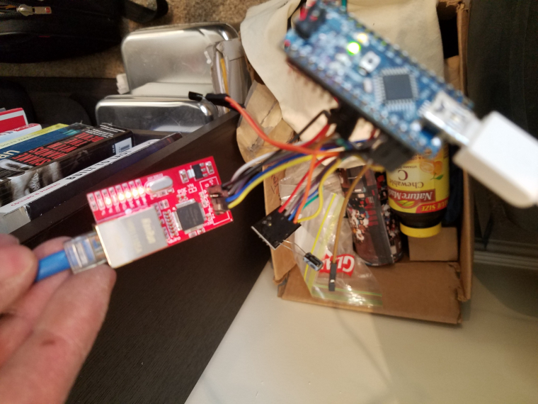
I cant think of anything else to try. Im thinking there must be something wrong with my ethernet board? Is the wire I am using to small for this particular application. I used these same jumpers to make the USB gateway and everything seems to be fine. Attached is a pic of the ethernet module Im using and then another pic of the setup in case you see something glaring that is wrong. Let me know if you need more pics.
Thanks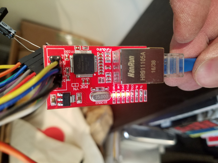
-
-
@blacey Thanks again for the suggestions. I tried several.
-
I switched the capacitor to a 47uF 25v. When I did that, there was no change.
-
I checked the boards manager and everything is as you said.
-
I changed the power supply to a 1 amp and then also a 2 amp and tried to power everything VIA or THROUGH the arduino and then also I tried to power everything separtely and just split off to each device and still nothing.
-
I also changed out the radio module just to make sure it wasnt a bad unit or something like that.
-
I also upgraded IDE to the latest and uploaded that new code from the new IDE and still nothing.
-
I used a powered USB hub and hooked it up to the computer so I could still read the serial and still, nothing.
-
I tried to use the 3.3v from the nano and also separately from a voltage regulator that was suggested in the tutorial and still, nothing.
Everytime I try this ideas I get the same log as I did before.
I cant think of anything else to try. Im thinking there must be something wrong with my ethernet board? Is the wire I am using to small for this particular application. I used these same jumpers to make the USB gateway and everything seems to be fine. Attached is a pic of the ethernet module Im using and then another pic of the setup in case you see something glaring that is wrong. Let me know if you need more pics.
Thanks
@hoggin It sounds like you are doing all the right things but it still looks like a radio power problem, especially if you are now running the latest IDE and atmel boards file. For additional context, here is a good reference for solving NRF power issues - https://arduino-info.wikispaces.com/Nrf24L01-2.4GHz-HowTo#PP
Which 3.3VDC LDO did you use? I recently had power issues using an LE33ACZ regulator and had to switch to an AMS117 3.3V to solve the problem because the LE33ACZ couldn't deliver enough amperes.
That said, don't run anything off the nano built-in voltage regulator because it typically can't supply enough current. I would power the nano over USB, power a high-current 3.3v LDO regulator from an external 5VDC power supply for the radio with a 47uf capacitor and direct connect the 5VDC external power supply into the WS5100 Ethernet module (ensure there is a common ground between all).
I have a nano, NRF24L01+ and WS5100 on hand but I think if I try to repo your problem I won't be able to because it is something specific to your config...
-
-
@blacey I was using the LE33ACZ. So are you pretty positive that this is a radio problem and not an ethernet problem? I ordered several of the AMS117 units and will have to wait for them to arrive to begin the testing.
@hoggin said in Ethernet gateway shows up on vera , but doens't want to include devices:
@blacey I was using the LE33ACZ. So are you pretty positive that this is a radio problem and not an ethernet problem? I ordered several of the AMS117 units and will have to wait for them to arrive to begin the testing.
Yes, I am... Your gateway reboots when the radio sends an ACK. I had the exact same problem/symptoms that you are experiencing on a serial gateway and a couple nodes and switching the LE33ACZ out for an AMS117 to power the radio, albeit on a node, and in my case adding additional capacitors, resolved the issues. The gateway and nodes ran perfectly for years but failed when I upgraded to a newer version of the MySensors library - the root cause was that the MySensors protocol stack had been optimized significantly (thanks to @tekka) so it was able to drive the radio a bit harder which in turn increased the current. We even toyed with adding an option to slow the protocol stack down but quickly cast that aside.
Please let us know the results when you replace the LE33ACZ LDO with an AMS117.
-
@blacey Took a while to get the part for the new power supply but I finally got it. Turns out that it was not the problem. I reattached everything both with separate power supplies and with just one 2 amp power supply and still I got the rebooting. With all of this in mind I went hunting for more answers. I FINALLY figured it out. I found another post here and here that got me down the right path. I had upgraded everthing per everyones recommenations and that seemed to be causing the issue. I downgraded to "Arduino IDE 1.6.11" and that worked. I completely uninstalled arduino from my system and just started over with the older version. I assembled everything as I had done before and it just fired right up. The mysensors library I used was 2.0.0 and again it all worked perfectly. I was amazed. I didnt have to comment out the debug or do anything other than follow the tutorial EXCEPT only use 1.6.11 to upload it all.
Thank you for all the help with everything. -
@hoggin At least according to my experience, just downgrading the AVR Board Definitions to <=1.6.11 using the Board-Manager within an recent version of the IDE should have done the trick; downgrade of the other libs including mysensors (2.1.1) was not necessary.
In Addition: For the serial Gateways this kind of trouble seems to be solved since version 1.6.18 of the AVR-Board definitions (shipped since several weeks).
Hello! It looks like you're interested in this conversation, but you don't have an account yet.
Getting fed up of having to scroll through the same posts each visit? When you register for an account, you'll always come back to exactly where you were before, and choose to be notified of new replies (either via email, or push notification). You'll also be able to save bookmarks and upvote posts to show your appreciation to other community members.
With your input, this post could be even better 💗
Register Login