[solved] new controller with ethernet Gateway on UI7 - unable to enter inclusion mode
-
I think it is enabled by default.
This is how I compiled it
// Enable inclusion mode
#define MY_INCLUSION_MODE_FEATURE
// Enable Inclusion mode button on gateway
//#define MY_INCLUSION_BUTTON_FEATURE
// Set inclusion mode duration (in seconds)
#define MY_INCLUSION_MODE_DURATION 60
// Digital pin used for inclusion mode button
//#define MY_INCLUSION_MODE_BUTTON_PIN  3
So only inclusion by button press on the gw is disabled?
-
I realized there is a new version 2.1.1, I had used 2.1.0
I flashed both gw and sensor node with the new version.
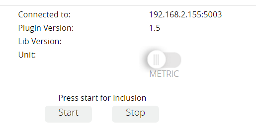
Now on vera gui in the Mysensor plugin both plugin version and lib version are shown correctly.
Debug output from gw shows communication to the node is ok.
Still, no inclusion mode. -
Na, I would't mess with my system either :blush:
I had mysensors running nicely on ui5, too.
That changed when Vera Plus moved in.;-)
Tried building a pi gw, but face the problem. No chance to enter inclusion mode.@pls90 I have a few Ethernet GWs working on UI7 so I think it should work also for you.
Maybe you could try rebooting your Vera, then after that also do a few Lua Engine restarts and then finally you do a Ctrl + F5 to get a browser refresh.
Then try the inclusion again.
Maybe you could also post your complete GW sketch so I can compare with some of the once I'm using.
Please also check your Arduino IDE version and AVR Boards Version. -
@korttoma Thank you for taking your time to have a look.
I did as you suggested abd did the vera dance (vera reboot, reload luup engine, clear browser cache) to no avail.
Here's my gw sketch (should be nearly unchanged from the template)// Enable debug prints to serial monitor #define MY_DEBUG // Enable and select radio type attached #define MY_RADIO_NRF24 //#define MY_RADIO_RFM69 // Enable gateway ethernet module type #define MY_GATEWAY_W5100 // W5100 Ethernet module SPI enable (optional if using a shield/module that manages SPI_EN signal) //#define MY_W5100_SPI_EN 4 // Enable Soft SPI for NRF radio (note different radio wiring is required) // The W5100 ethernet module seems to have a hard time co-operate with // radio on the same spi bus. #if !defined(MY_W5100_SPI_EN) && !defined(ARDUINO_ARCH_SAMD) #define MY_SOFTSPI #define MY_SOFT_SPI_SCK_PIN 14 #define MY_SOFT_SPI_MISO_PIN 16 #define MY_SOFT_SPI_MOSI_PIN 15 #endif // When W5100 is connected we have to move CE/CSN pins for NRF radio #ifndef MY_RF24_CE_PIN #define MY_RF24_CE_PIN 5 #endif #ifndef MY_RF24_CS_PIN #define MY_RF24_CS_PIN 6 #endif // Enable to UDP //#define MY_USE_UDP #define MY_IP_ADDRESS 192,168,2,155 // If this is disabled, DHCP is used to retrieve address // Renewal period if using DHCP //#define MY_IP_RENEWAL_INTERVAL 60000 // The port to keep open on node server mode / or port to contact in client mode #define MY_PORT 5003 // Controller ip address. Enables client mode (default is "server" mode). // Also enable this if MY_USE_UDP is used and you want sensor data sent somewhere. //#define MY_CONTROLLER_IP_ADDRESS 192, 168, 178, 254 // The MAC address can be anything you want but should be unique on your network. // Newer boards have a MAC address printed on the underside of the PCB, which you can (optionally) use. // Note that most of the Ardunio examples use "DEAD BEEF FEED" for the MAC address. #define MY_MAC_ADDRESS 0xFE, 0xED, 0xDE, 0xAD, 0xBE, 0xEF // Enable inclusion mode #define MY_INCLUSION_MODE_FEATURE // Enable Inclusion mode button on gateway //#define MY_INCLUSION_BUTTON_FEATURE // Set inclusion mode duration (in seconds) #define MY_INCLUSION_MODE_DURATION 60 // Digital pin used for inclusion mode button //#define MY_INCLUSION_MODE_BUTTON_PIN 3 // Set blinking period #define MY_DEFAULT_LED_BLINK_PERIOD 300 // Flash leds on rx/tx/err // Uncomment to override default HW configurations //#define MY_DEFAULT_ERR_LED_PIN 7 // Error led pin //#define MY_DEFAULT_RX_LED_PIN 8 // Receive led pin //#define MY_DEFAULT_TX_LED_PIN 9 // Transmit led pin #if defined(MY_USE_UDP) #include <EthernetUdp.h> #endif #include <Ethernet.h> #include <MySensors.h> void setup() { } void loop() { }Which lib version are you currently using?
-
I did some more testing.
I downloaded lib version 1.5 and flashed the gateway and sensor node again.
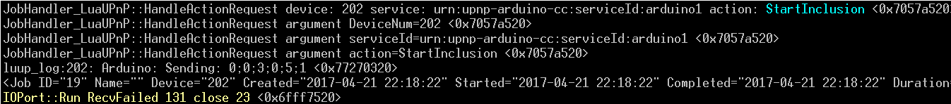
Inclusion worked right away, but it took me numerous attempts to get the sensor node to include. After it did that communication between the node and gw broke down a couple of times (I am look at the debug output of sensor and gw). The sensor should report temp and lux level, which it has not done so far.
On 2.1.1 communication seemed to be solid.
Now I a stuck between 2.1.1 which will not allow inclusion of nodes but has good communication, and 1.5 which created the devices but doesn't update them because of comm issues.
Sigh. -
On the SensebenderGW I have used 2.1.1 (Arduino IDE 1.6.11, AVR board 1.6.11)
On one ESP8266RFM69 GW I have also 2.1.1 (Arduino IDE 1.6.11, AVR board 1.6.11)
On another NRF24 Ethernet GW I have used 2.0.0 (Don't remember IDE/AVR version)
On an RFM69 Ethernet GW I have used 2.1.0 (Don't remember IDE/AVR version)All of them are currently in use and working with different sketches of course.
Sensebender GW sketch:
/**
 * The MySensors Arduino library handles the wireless radio link and protocol
 * between your home built sensors/actuators and HA controller of choice.
 * The sensors forms a self healing radio network with optional repeaters. Each
 * repeater and gateway builds a routing tables in EEPROM which keeps track of the
 * network topology allowing messages to be routed to nodes.
 *
 * Created by Henrik Ekblad <henrik.ekblad@mysensors.org>
 * Copyright (C) 2013-2015 Sensnology AB
 * Full contributor list: https://github.com/mysensors/Arduino/graphs/contributors
 *
 * Documentation: http://www.mysensors.org
 * Support Forum: http://forum.mysensors.org
 *
 * This program is free software; you can redistribute it and/or
 * modify it under the terms of the GNU General Public License
 * version 2 as published by the Free Software Foundation.
 *
 *******************************
 *
 * REVISION HISTORY
 * Version 1.0 - Henrik EKblad
 * Contribution by a-lurker and Anticimex,
 * Contribution by Norbert Truchsess <norbert.truchsess@t-online.de>
 * Contribution by Tomas Hozza <thozza@gmail.com>
 *
 *
 * DESCRIPTION
 * The EthernetGateway sends data received from sensors to the ethernet link.
 * The gateway also accepts input on ethernet interface, which is then sent out to the radio network.
 *
 * The GW code is designed for Arduino 328p / 16MHz.  ATmega168 does not have enough memory to run this program.
 *
 * LED purposes:
 * - To use the feature, uncomment MY_DEFAULT_xxx_LED_PIN in the sketch below
 * - RX (green) - blink fast on radio message recieved. In inclusion mode will blink fast only on presentation recieved
 * - TX (yellow) - blink fast on radio message transmitted. In inclusion mode will blink slowly
 * - ERR (red) - fast blink on error during transmission error or recieve crc error
 *
 * See http://www.mysensors.org/build/ethernet_gateway for wiring instructions.
 *
 */

// Enable debug prints to serial monitor
//#define MY_DEBUG

// Enable and select radio type attached
#define MY_RADIO_NRF24
//#define MY_RADIO_RFM69

// Enable gateway ethernet module type
#define MY_GATEWAY_W5100

// W5100 Ethernet module SPI enable (optional if using a shield/module that manages SPI_EN signal)
//#define MY_W5100_SPI_EN 4

// Enable Soft SPI for NRF radio (note different radio wiring is required)
// The W5100 ethernet module seems to have a hard time co-operate with
// radio on the same spi bus.
#if !defined(MY_W5100_SPI_EN) && !defined(ARDUINO_ARCH_SAMD)
#define MY_SOFTSPI
#define MY_SOFT_SPI_SCK_PIN 14
#define MY_SOFT_SPI_MISO_PIN 16
#define MY_SOFT_SPI_MOSI_PIN 15
#endif

// When W5100 is connected we have to move CE/CSN pins for NRF radio
#ifndef MY_RF24_CE_PIN
#define MY_RF24_CE_PIN 5
#endif
#ifndef MY_RF24_CS_PIN
#define MY_RF24_CS_PIN 6
#endif

// Enable to UDP
//#define MY_USE_UDP

#define MY_IP_ADDRESS 192,168,1,100   // If this is disabled, DHCP is used to retrieve address
// Renewal period if using DHCP
//#define MY_IP_RENEWAL_INTERVAL 60000
// The port to keep open on node server mode / or port to contact in client mode
#define MY_PORT 5003

#define MY_GATEWAY_MAX_CLIENTS 3

// Controller ip address. Enables client mode (default is "server" mode).
// Also enable this if MY_USE_UDP is used and you want sensor data sent somewhere.
//#define MY_CONTROLLER_IP_ADDRESS 192, 168, 178, 254

// The MAC address can be anything you want but should be unique on your network.
// Newer boards have a MAC address printed on the underside of the PCB, which you can (optionally) use.
// Note that most of the Ardunio examples use  "DEAD BEEF FEED" for the MAC address.
#define MY_MAC_ADDRESS 0xDE, 0xAD, 0xBE, 0xEF, 0xFE, 0xFE

// Enable inclusion mode
#define MY_INCLUSION_MODE_FEATURE
// Enable Inclusion mode button on gateway
//#define MY_INCLUSION_BUTTON_FEATURE
// Set inclusion mode duration (in seconds)
#define MY_INCLUSION_MODE_DURATION 60
// Digital pin used for inclusion mode button
//#define MY_INCLUSION_MODE_BUTTON_PIN  3

// Set blinking period
#define MY_DEFAULT_LED_BLINK_PERIOD 300

// Flash leds on rx/tx/err
// Uncomment to override default HW configurations
//#define MY_DEFAULT_ERR_LED_PIN 7  // Error led pin
//#define MY_DEFAULT_RX_LED_PIN  8  // Receive led pin
//#define MY_DEFAULT_TX_LED_PIN  9  // Transmit led pin


#if defined(MY_USE_UDP)
#include <EthernetUdp.h>
#endif
#include <Ethernet.h>
#include <MySensors.h>


void setup()
{
}

void loop()
{
}
Please check your IDE and AVR versions.
-
As you confirmed you had your gw / sensors running on 2.x I gave it another try and started from scratch, and wiped the eeproms on both my gw and node.
New Install of Arduino IDE, new MySensors Library install. I used the ethernet gw sketch example and a temperature sensor node sketch.
This time it worked, I was able to finally include the sensor, what I can tell from the debug output communication seems to be working flawless.
Even when cutting power from gw or sensor and powering up again communication is recovering.
Now I will work on adapting my old sensor node sketch on lib 1.4 to new 2.1 requirements.
Thank you so much for taking the time to help me get this going :smiley:
Hello! It looks like you're interested in this conversation, but you don't have an account yet.
Getting fed up of having to scroll through the same posts each visit? When you register for an account, you'll always come back to exactly where you were before, and choose to be notified of new replies (either via email, or push notification). You'll also be able to save bookmarks and upvote posts to show your appreciation to other community members.
With your input, this post could be even better 💗
Register Login