Cutting the voltage regulator
-
It's not clear to me how to properly cut the regulator. According to this documentation it should suffice to cut one leg but then I don't see how this could work?
This is the board I'm using:
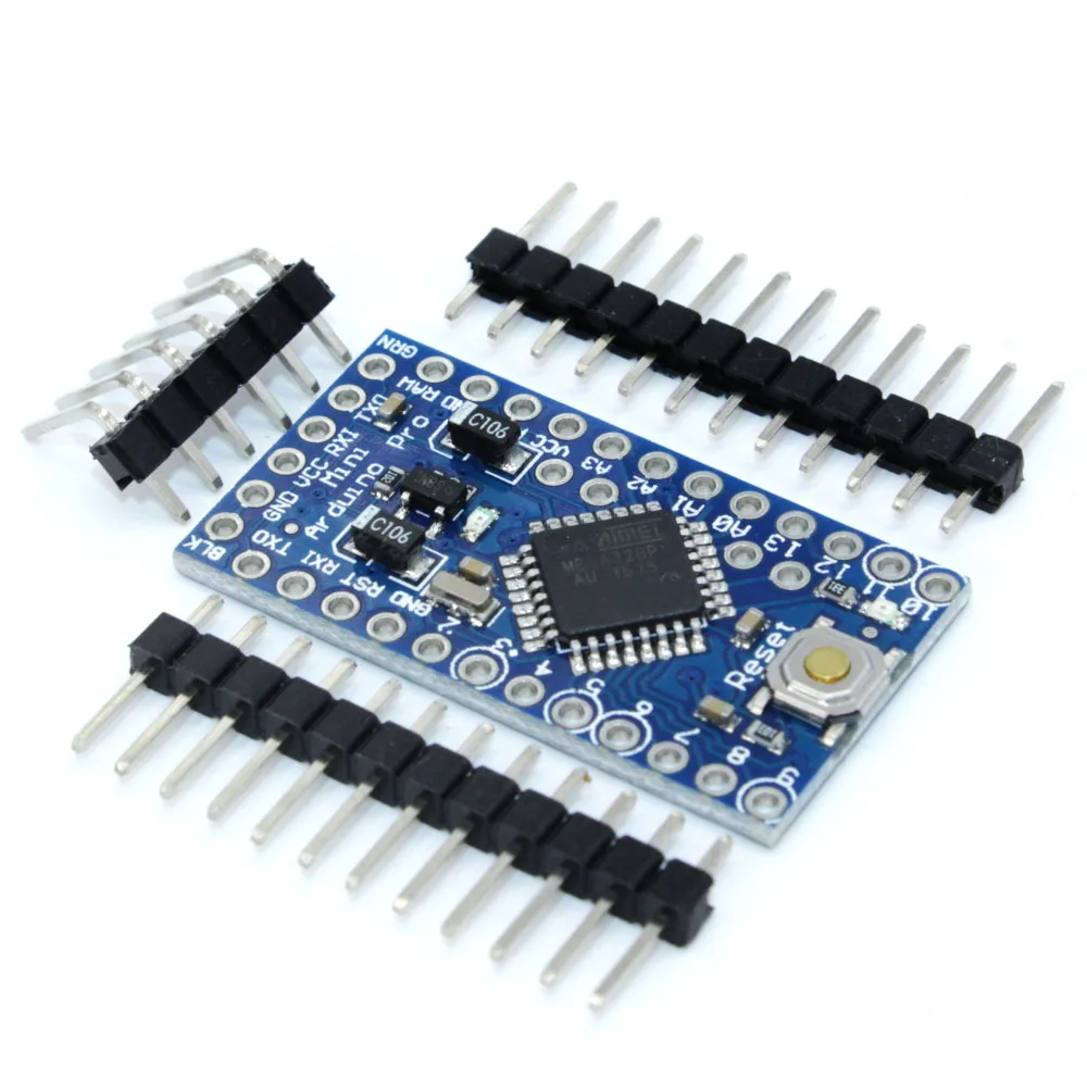
Should I completely remove the regulator? Or how will it work if I only cut the lower right leg?
I tried cutting the wire just before the circle as marked on the image but then I couldn't program the board anymore. Perhaps I cut it in the wrong place or I'm feeding it gnd/vcc wrongly?
-
It's not clear to me how to properly cut the regulator. According to this documentation it should suffice to cut one leg but then I don't see how this could work?
This is the board I'm using:
Should I completely remove the regulator? Or how will it work if I only cut the lower right leg?
I tried cutting the wire just before the circle as marked on the image but then I couldn't program the board anymore. Perhaps I cut it in the wrong place or I'm feeding it gnd/vcc wrongly?
@mpp - i find it much harder to cut a leg/trace then desolder everything. I put my soldering iron on one side over all pins and bend gently upp. When they are free from the pads i desolder the other side and it comes off. Same with led/resistor. I never cut, always desolder. I have broken to many trying to cut.
Controller: Proxmox VM - Home Assistant
MySensors GW: Arduino Uno - W5100 Ethernet, Gw Shield Nrf24l01+ 2,4Ghz
MySensors GW: Arduino Uno - Gw Shield RFM69, 433mhz
RFLink GW - Arduino Mega + RFLink Shield, 433mhz -
@mpp - i find it much harder to cut a leg/trace then desolder everything. I put my soldering iron on one side over all pins and bend gently upp. When they are free from the pads i desolder the other side and it comes off. Same with led/resistor. I never cut, always desolder. I have broken to many trying to cut.
thanks @sundberg84, seems like I broke mine as well. Some questions remain:
- How can the board keep working when it is completely removed, don't you need to bridge some pads?
- What pins should I use to program it (There's only one VCC pint but some arduino clones seem indicate several GND pins where some other indicate blk or dtr)
- What voltage do I supply without the regulator (I assume 3.3)?
-
thanks @sundberg84, seems like I broke mine as well. Some questions remain:
- How can the board keep working when it is completely removed, don't you need to bridge some pads?
- What pins should I use to program it (There's only one VCC pint but some arduino clones seem indicate several GND pins where some other indicate blk or dtr)
- What voltage do I supply without the regulator (I assume 3.3)?
How can the board keep working when it is completely removed, don't you need to bridge some pads?
No, you need to feed a regulated voltage to VCC. The "easy" explanation is that the voltage regulator is only engaged when providing a powersource to RAW.
What pins should I use to program it (There's only one VCC pint but some arduino clones seem indicate several GND pins where some other indicate blk or dtr)
On the short side there are the ftdi header you use to program the board with. Check here (swedish but you see the pictures)
What voltage do I supply without the regulator (I assume 3.3)?
You need to regulate to voltage to a stable 3.3v (or below depending on BOD/fuses) and provide it to VCC.
-
I agree with @sundberg84 it's much easier to unsolder it than butchering the PCB :)
Check the video here, not good quality but you will get the point
https://www.youtube.com/watch?v=7qujkC72dYs -
I agree with @sundberg84 it's much easier to unsolder it than butchering the PCB :)
Check the video here, not good quality but you will get the point
https://www.youtube.com/watch?v=7qujkC72dYs@Nca78 - great informative video!
I remove the regulator to the right (marked 102) since this is connected in series (same result as removing the led) with the led and easier to get to. The led is cramped in between the regulator and the capacitor so might be easier if the setup is the same on your boards... -
@Nca78 - great informative video!
I remove the regulator to the right (marked 102) since this is connected in series (same result as removing the led) with the led and easier to get to. The led is cramped in between the regulator and the capacitor so might be easier if the setup is the same on your boards...@sundberg84 yes you are right, and resistors heat up more easily also so it might be a 2 seconds job, I'll do it next time.
And in any case it would be better to remove regulator first. -
How can the board keep working when it is completely removed, don't you need to bridge some pads?
No, you need to feed a regulated voltage to VCC. The "easy" explanation is that the voltage regulator is only engaged when providing a powersource to RAW.
What pins should I use to program it (There's only one VCC pint but some arduino clones seem indicate several GND pins where some other indicate blk or dtr)
On the short side there are the ftdi header you use to program the board with. Check here (swedish but you see the pictures)
What voltage do I supply without the regulator (I assume 3.3)?
You need to regulate to voltage to a stable 3.3v (or below depending on BOD/fuses) and provide it to VCC.
Thanks for the tips.
No, you need to feed a regulated voltage to VCC. The "easy" explanation is that the voltage regulator is only engaged when providing a powersource to RAW.
I don't get this, I never use RAW so there's no advantage in removing the regulator.. ?
Isn't it the other way round, that the regulator is only engaged when using VCC?
-
Thanks for the tips.
No, you need to feed a regulated voltage to VCC. The "easy" explanation is that the voltage regulator is only engaged when providing a powersource to RAW.
I don't get this, I never use RAW so there's no advantage in removing the regulator.. ?
Isn't it the other way round, that the regulator is only engaged when using VCC?
@mpp - No, the voltage regulator is engaged when providing power to RAW and regulates the voltages down from whatever you input to 5v. Therefore you can remove it when providing a stable power source to VCC. What happens though is that there is a drain/leakage of current even when you provide power to VCC. Therefore its good to remove it.
Edit: Therefore... I love my Swedenglish...
Hello! It looks like you're interested in this conversation, but you don't have an account yet.
Getting fed up of having to scroll through the same posts each visit? When you register for an account, you'll always come back to exactly where you were before, and choose to be notified of new replies (either via email, or push notification). You'll also be able to save bookmarks and upvote posts to show your appreciation to other community members.
With your input, this post could be even better 💗
Register Login