nRF5 action!


  • Hero Member

    In lieu of my breakout board, which hasn't yet arrived, I've been attaching wires directly to the module so that I can do more than just sit and wait for the BoB delivery. I'm now doing it this way:
    0_1501085660176_attachments.jpg
    and although crude it's working much better than just soldering the wire to the module with no mechanical support. Doing it the way pictured, the connections stay connected and don't break loose. 🙂 Ironically, by the time my breakout boards finally do arrive, I may have already learned everything I needed them for.

    I am curious: how are the rest of you handling this issue?

    [Edit: One other alternative: once my 1.27mm pitch generic protoboards arrive, I expect they'll offer up cleaner connection possibilities. At the moment, I'm also waiting for them to arrive from Aliexpress....]


  • Contest Winner

    @NeverDie said in nRF5 Bluetooth action!:

    Your idea of having the pin mapping be selectable within the sketch sounds great! A+. I'm really looking forward to that and hope that you can do it soon.

    With merging this pull request the feature should be available: https://github.com/mysensors/ArduinoBoards/pull/13

    Documentation can be found at https://github.com/mysensors/ArduinoHwNRF5


  • Contest Winner

    @d00616 said in nRF5 Bluetooth action!:

    With merging this pull request the feature should be available: https://github.com/mysensors/ArduinoBoards/pull/13

    Merged. Have fun with board definition in your sketch.


  • Hardware Contributor

    @NeverDie said in nRF5 Bluetooth action!:

    I am curious: how are the rest of you handling this issue?

    Not many solutions, I soldered wires directly to the modules too, I used thin&cheap wires from aliexpress. They are very convenient for this, easy to solder and very soft so not having any constraint on the solder joints when you manipulate them. Then I put module on the side of board with double sided tape and soldered other ends of the wires to a connector.
    0_1501138745943_nrf52_1.jpg
    Then I flip everything and only look at the beautiful side of things 😄
    0_1501138753206_nrf52_2.jpg


  • Hero Member

    @d00616 said in nRF5 Bluetooth action!:

    @d00616 said in nRF5 Bluetooth action!:

    With merging this pull request the feature should be available: https://github.com/mysensors/ArduinoBoards/pull/13

    Merged. Have fun with board definition in your sketch.

    Thanks! By being "merged," does that mean it is now in the regular MySensors development release, and so I should reload a fresh copy of the MySensors development library?

    Also, is this the way I should enable P0.21 as nReset (to enable hardware resets on P0.21), or should I instead be writing 0xFFFF directly to both the PSELRESET[0] and PSELRESET[1] registers to enable that?


  • Mod

    This post is deleted!

  • Contest Winner

    @NeverDie said in nRF5 Bluetooth action!:

    Thanks! By being "merged," does that mean it is now in the regular MySensors development release, and so I should reload a fresh copy of the MySensors development library?

    The Board definition is independed from MySensors core living at https://github.com/mysensors/ArduinoBoards You have to follow the instructions, then you can install the MySensors nRF5 Boards via Arduino Board Manager.

    Also, is this the way I should enable P0.21 as nReset (to enable hardware resets on P0.21), or should I instead be writing 0xFFFF directly to both the PSELRESET[0] and PSELRESET[1] registers to enable that?

    Look into the Tools menu. For nRF52 MCU is a "Reset" menu. Switch it to "Enable"


  • Hero Member

    @d00616
    I got the pin mapping to work, but setting reset enable through the tool menu seems to have no effect. I subsequently drive P0.21 low (all the way to GND even), but no reset happens. Am I doing it wrong? Anyone gotten it to work?


  • Hero Member

    @NeverDie
    I also tried adding a 10K pullup resistor, and no change.

    At the moment I'm unfamiliar with the nRF52 API. What would the code be to set both those reset registers to 0xFFFF? That by itself should enable the reset on P0.21. I could try inserting it into the demo script and see if reset then works.


  • Hero Member

    I guess it wouldn't be that simple, because I just now read that it requires a system reset after writing to those registers: https://devzone.nordicsemi.com/question/157603/can-i-enable-and-disable-nrf52832-reset-pin-when-code-is-running/ for it to take effect.


  • Hardware Contributor

    @NeverDie said in nRF5 Bluetooth action!:

    By switching to a Windows 10 computer, I was able to get J-link working over USB from windows.

    Can you explain the steps you used for that ?
    Did you use a jlink clone or the version included in the DK ?


  • Hardware Contributor

    @Nca78 said in nRF5 Bluetooth action!:

    @NeverDie said in nRF5 Bluetooth action!:

    By switching to a Windows 10 computer, I was able to get J-link working over USB from windows.

    Can you explain the steps you used for that ?
    Did you use a jlink clone or the version included in the DK ?

    Well you can forget about my questions.
    I tried to use the JLink tools to make the mass erase but it didn't want to connect to the module.
    But then I have replaced the driver with Zadig and configured Arduino for NRF5 and it uploaded the LightSensor sketch, I can see it in the log of the controller. No mass erase needed, nor any unlock or related command.
    Just plug and program for me 😄

    I have some strange error messages but I guess they come from (very) dated firmware on my Segger clone

    ** Programming Started **
    auto erase enabled
    Info : nRF51822-QFN48(build code: B00) 512kB Flash
    Warn : not enough working area available(requested 32)
    Warn : no working area available, falling back to slow memory writes
    wrote 28672 bytes from file C:\Users\Nicolas\AppData\Local\Temp\arduino_build_723618/LightSensor.ino.hex in 6.715397s (4.170 KiB/s)
    ** Programming Finished **
    ** Verify Started **
    Warn : not enough working area available(requested 52)
    verified 27432 bytes in 0.279278s (95.923 KiB/s)
    ** Verified OK **
    ** Resetting Target **
    shutdown command invoked
    

  • Hero Member

    @Nca78 said in nRF5 Bluetooth action!:

    Did you use a jlink clone or the version included in the DK ?

    I used the j-link Segger clone to do the mass erase, and then I switched to the DK to do the programming. However, today I was able to do the programming from the Segger clone on the Windows 10 computer, and the setup is less arduous than for programming an external chip using the DK (because with the Segger I didn't have to power the target chip independently during the programming).


  • Hero Member

    So, I guess the way the code would read is:

    1. First check if the reset registers are already properly set.
    2. If so, then just move on to whatever is next.
      If not, then properly set the reset registers and invoke the system reset.

    Apparently a system reset doesn't change the values in the reset registers.

    Of course, none of this would be needed if the reset enable from the tools menu worked, so I'd still prefer to do it that way if at all possible.

    As I indicated earlier, the pin mapping on Rx and Tx did work using @d00616 new technique, so hurray for that. That much was an important victory in itself that's worth celebrating. 🙂


  • Hardware Contributor

    First nrf51822 module arrived already.
    It's really small, here between an nrf24 SMD and the cdebyte 52832.
    Soldering quality looks better than the pictures on AliExpress.
    0_1501235779537_IMAG1846.jpg


  • Contest Winner

    @NeverDie said in nRF5 Bluetooth action!:

    Apparently a system reset doesn't change the values in the reset registers.

    The "Reset" menu was from my first approach creating user manageable boards for arduino-nrf5. I haven' tested it. With the reset menu I set the "-DCONFIG_GPIO_AS_PINRESET" option. This option should be processed in "cores/nRF5/SDK/components/toolchain/system_nrf52.c". If not the SystemInit() function is not processed in the startup code. This is a problem handling the chip errata. I have not time to check this at the moment.

    Here is a PR which want to enable reset as default: https://github.com/sandeepmistry/arduino-nRF5/pull/91


  • Hero Member

    Maybe the reset pin problem is hardware related? I say that because if I program the Ebyte module as a Nordic nRF52832 DK board, it still has the same issue. In contrast, the reset button on the actual nRF52832 DK board does work as expected.


  • Hero Member

    I've confirmed that connecting P0.21 to GND and then removing it again on the Nordic nRF52832 DK does act as a reset. So, at the moment I have no idea why doing so on the Ebyte nRF52832 that's been programmed to think it's an Nordic nRF52832 DK doesn't do the same. There must be some hardware difference, right?


  • Hero Member

    I've confirmed that on both the Ebyte Module and on the Nordic nRF52832 DK, there is continuity between the P0.21 pin on the chip and the P0.21 pin on the board pinout. So, there must be some other factor that accounts for the difference.


  • Hero Member

    Making no headway on the reset topic, so for now I'm going to punt and move on to other things.


  • Hero Member

    Success! I received some of these modules:
    https://www.aliexpress.com/item/nRF52832-Bluetooth-4-1-BLE-Module-M4-Transparent-Transmission-SMA-512K-FLASH-64K-RAM-pass-through/32798522093.html?spm=2114.search0104.3.10.osbQHP&ws_ab_test=searchweb0_0,searchweb201602_5_10152_10065_10151_10068_10130_10084_10083_10119_10080_10307_10082_10081_10110_10178_10137_10111_10060_10112_10113_10155_10114_10154_10056_10055_10054_10310_10312_10059_100031_10099_10078_10079_10103_10073_10102_10120_10052_10053_10142_10107_10050_10051-10120,searchweb201603_2,ppcSwitch_5&btsid=b9a0c3cb-cc2a-4254-b24f-94136c73def6&algo_expid=2a71f70b-4929-43a5-887a-2f7263250568-1&algo_pvid=2a71f70b-4929-43a5-887a-2f7263250568
    which I immediately programmed using the nRF52832 DK. This time, there was no need to first mass erase. Furthermore, this time P0.21 does indeed reset the module after it is pulled to ground and then released.

    So, from this I conclude there must be something peculiar to the Ebyte modules which prevents their resetting using P0.21.

    It's nice to have different modules to compare amongst. 🙂


  • Mod

    @NeverDie gotta catch them all 🙂


  • Hero Member


  • Hero Member

    Anyone have a good sketch for measuring the battery supplied voltage on an nRF52? Some of the concepts from the old atmega328p may apply, but the specifics are going to be different, I'm sure.


  • Check on adafruits feather reference they use two resistors as a voltage divider for that simple and effective.


  • Hero Member

    @Mike_Lemo said in nRF5 Bluetooth action!:

    Check on adafruits feather reference they use two resistors as a voltage divider for that simple and effective.

    I'm not finding it. Do you have a link?


  • @NeverDie https://learn.adafruit.com/assets/39913

    Top right corner of the schematic.


  • @NeverDie but a much better but more expensive solution would be a lipo fuel guage from spark fun they use a Max chip for that.


  • Hardware Contributor

    If supplied with less than 3.6V you can do it with ADC, 1.2V voltage reference and 1/3 prescaling.
    But I've only looked at the theory yet.

    Rules are Vdd+0.3V max at the pin, and max 2.4V as input of ADC (after prescaling)


  • Hero Member

    Well, as you all know, on the atmega328p you can read the 1.1v gap voltage using the battery voltage as the reference voltage, by doing analogRead(A0), and from just that one measurement then calculate the battery voltage by doing a little bit of math. So, I'm just wondering what the code is to do the equivalent of that (using 1.2v instead of 1.1v) on the nRF52832.


  • Contest Winner

    @Nca78 said in nRF5 Bluetooth action!:

    If supplied with less than 3.6V you can do it with ADC, 1.2V voltage reference and 1/3 prescaling.
    But I've only looked at the theory yet.

    For this, you can use the implemented hwCPUVoltage() function. Reading the voltage costs nRF51: 260µA/20µs | nRF52: 700µA/3µs


  • Hero Member

    @d00616 said in nRF5 Bluetooth action!:

    hwCPUVoltage()

    I'm finally installing Visual Micro, because I hope it will help me quickly find where all these functions are defined. With all these new layers, the Arduino IDE is just no longer cutting it.


  • Hero Member

    LOL. Well, Visual Micro found it alright, but just in the wrong place. It found it in MyHwAVR.cpp


  • Hardware Contributor

    @NeverDie said in nRF5 Bluetooth action!:

    @d00616 said in nRF5 Bluetooth action!:

    hwCPUVoltage()

    I'm finally installing Visual Micro, because I hope it will help me quickly find where all these functions are defined. With all these new layers, the Arduino IDE is just no longer cutting it.

    good choice 👍
    for nrf5, the function is located in MyHwNRF5.cpp


  • Hero Member

    @d00616 said in nRF5 Bluetooth action!:

    For this, you can use the implemented hwCPUVoltage() function.

    I tried this function call on an nRF52 DK, and it seems to work. I then tried it on an Ebyte module, treated as an nRF52 DK "board", and it reported zero voltage. So, probably I just need to do a pin mapping so that it reads the voltage on the proper pin. But which pin/mapping would it be? I thought that Vcc wouldn't really be mappable to anything but Vcc. I guess whichever analog pin (if that's what it is?) is connected to Vcc on the nRF52 DK is the pin I need to find and re-map to its equivalent pin on the Ebyte module. Hmmm.... I'll have to look into which one that would be.


  • Hero Member

    Actually, something different may be going on. Here's the function definition:

    uint16_t hwCPUVoltage()
    {
    	// VDD is prescaled 1/3 and compared with the internal 1.2V reference
    	Serial.println("Inside hwCPUVoltage function.");
    #if defined(NRF_ADC)
        Serial.println("This is an NRF_ADC.");
    	// NRF51:
    	// Sampling is done with lowest resolution to minimize the time
    	// 20uS@260uA
    
    	// Concurrent ressource: disable
    	uint32_t lpcomp_enabled = NRF_LPCOMP->ENABLE;
    	NRF_LPCOMP->ENABLE = 0;
    
    	// Enable and configure ADC
    	NRF_ADC->ENABLE = 1;
    	NRF_ADC->CONFIG = (ADC_CONFIG_EXTREFSEL_None << ADC_CONFIG_EXTREFSEL_Pos) |
    	                  (ADC_CONFIG_PSEL_Disabled << ADC_CONFIG_PSEL_Pos) |
    	                  (ADC_CONFIG_REFSEL_VBG << ADC_CONFIG_REFSEL_Pos) |
    	                  (ADC_CONFIG_INPSEL_SupplyOneThirdPrescaling << ADC_CONFIG_INPSEL_Pos) |
    	                  (ADC_CONFIG_RES_8bit << ADC_CONFIG_RES_Pos);
    	NRF_ADC->EVENTS_END = 0;
    	NRF_ADC->TASKS_START = 1;
    	while(!NRF_ADC->EVENTS_END);
    	NRF_ADC->EVENTS_END = 0;
    	int32_t sample = (int32_t)NRF_ADC->RESULT;
    	NRF_ADC->TASKS_STOP = 1;
    	NRF_ADC->ENABLE = 0;
    
    	// Restore LPCOMP state
    	NRF_LPCOMP->ENABLE = lpcomp_enabled;
    
    	return (sample*3600)/255;
    
    #elif defined(NRF_SAADC)
    	// NRF52:
    	// Sampling time 3uS@700uA
    	Serial.println("This is an NRF_SAADC.");
    	int32_t sample;
    	NRF_SAADC->ENABLE = SAADC_ENABLE_ENABLE_Enabled << SAADC_ENABLE_ENABLE_Pos;
    	NRF_SAADC->RESOLUTION = SAADC_RESOLUTION_VAL_8bit << SAADC_RESOLUTION_VAL_Pos;
    	NRF_SAADC->CH[0].PSELP = SAADC_CH_PSELP_PSELP_VDD << SAADC_CH_PSELP_PSELP_Pos;
    	NRF_SAADC->CH[0].CONFIG = (SAADC_CH_CONFIG_BURST_Disabled << SAADC_CH_CONFIG_BURST_Pos) |
    	                          (SAADC_CH_CONFIG_MODE_SE << SAADC_CH_CONFIG_MODE_Pos) |
    	                          (SAADC_CH_CONFIG_TACQ_3us << SAADC_CH_CONFIG_TACQ_Pos) |
    	                          (SAADC_CH_CONFIG_REFSEL_Internal << SAADC_CH_CONFIG_REFSEL_Pos) |
    	                          (SAADC_CH_CONFIG_GAIN_Gain1_6 << SAADC_CH_CONFIG_GAIN_Pos) |
    	                          (SAADC_CH_CONFIG_RESN_Bypass << SAADC_CH_CONFIG_RESN_Pos) |
    	                          (SAADC_CH_CONFIG_RESP_Bypass << SAADC_CH_CONFIG_RESP_Pos);
    	NRF_SAADC->OVERSAMPLE = SAADC_OVERSAMPLE_OVERSAMPLE_Bypass << SAADC_OVERSAMPLE_OVERSAMPLE_Pos;
    	NRF_SAADC->SAMPLERATE = SAADC_SAMPLERATE_MODE_Task << SAADC_SAMPLERATE_MODE_Pos;
    	NRF_SAADC->RESULT.MAXCNT = 1;
    	NRF_SAADC->RESULT.PTR = (uint32_t)&sample;
    
    	NRF_SAADC->EVENTS_STARTED = 0;
    	NRF_SAADC->TASKS_START = 1;
    	while (!NRF_SAADC->EVENTS_STARTED);
    	NRF_SAADC->EVENTS_STARTED = 0;
    
    	NRF_SAADC->EVENTS_END = 0;
    	NRF_SAADC->TASKS_SAMPLE = 1;
    	while (!NRF_SAADC->EVENTS_END);
    	NRF_SAADC->EVENTS_END = 0;
    
    	NRF_SAADC->EVENTS_STOPPED = 0;
    	NRF_SAADC->TASKS_STOP = 1;
    	while (!NRF_SAADC->EVENTS_STOPPED);
    	NRF_SAADC->EVENTS_STOPPED = 1;
    
    	NRF_SAADC->ENABLE = (SAADC_ENABLE_ENABLE_Disabled << SAADC_ENABLE_ENABLE_Pos);
    
    	return (sample*3600)/255;
    #else
    	Serial.println("Unknown MCU!!");
    	// unknown MCU
    	return 0;
    #endif
    }
    

    One, perhaps likely, theory would be that it doesn't recognize the MCU, which would explain why it returns the value of zero. Well, to debug that, I added the Serial.println(...) statements into the library code (see above) in an attempt to see which of the if-else branches is being taken, but none of the Serial.println(...)'s were printed! Here's a sample of the output from the Ebyte Module:

    332641 TSF:MSG:SEND,255-255-255-255,s=255,c=3,t=7,pt=0,l=0,sg=0,ft=0,st=OK:
    332968 TSF:MSG:READ,0-0-255,s=255,c=3,t=8,pt=1,l=1,sg=0:0
    332973 TSF:MSG:FPAR OK,ID=0,D=1
    334649 TSM:FPAR:OK
    334650 TSM:ID
    334651 TSM:ID:REQ
    334654 TSF:MSG:SEND,255-255-0-0,s=59,c=3,t=3,pt=0,l=0,sg=0,ft=0,st=OK:
    336662 TSM:ID
    336663 TSM:ID:REQ
    336665 TSF:MSG:SEND,255-255-0-0,s=23,c=3,t=3,pt=0,l=0,sg=0,ft=0,st=OK:
    338673 TSM:ID
    338674 TSM:ID:REQ
    338676 TSF:MSG:SEND,255-255-0-0,s=242,c=3,t=3,pt=0,l=0,sg=0,ft=0,st=OK:
    340684 TSM:ID
    340685 TSM:ID:REQ
    340687 TSF:MSG:SEND,255-255-0-0,s=205,c=3,t=3,pt=0,l=0,sg=0,ft=0,st=OK:
    342695 !TSM:ID:FAIL
    342696 TSM:FAIL:CNT=7
    342698 TSM:FAIL:DIS
    342700 TSF:TDI:TSL
    402703 TSM:FAIL:RE-INIT
    402705 TSM:INIT
    402706 TSM:INIT:TSP OK
    402708 TSM:FPAR
    402711 TSF:MSG:SEND,255-255-255-255,s=255,c=3,t=7,pt=0,l=0,sg=0,ft=0,st=OK:
    403472 TSF:MSG:READ,0-0-255,s=255,c=3,t=8,pt=1,l=1,sg=0:0
    403478 TSF:MSG:FPAR OK,ID=0,D=1
    404719 TSM:FPAR:OK
    404720 TSM:ID
    404721 TSM:ID:REQ
    404724 TSF:MSG:SEND,255-255-0-0,s=241,c=3,t=3,pt=0,l=0,sg=0,ft=0,st=OK:
    406732 TSM:ID
    406733 TSM:ID:REQ
    406735 TSF:MSG:SEND,255-255-0-0,s=205,c=3,t=3,pt=0,l=0,sg=0,ft=0,st=OK:
    408743 TSM:ID
    408744 TSM:ID:REQ
    408747 TSF:MSG:SEND,255-255-0-0,s=168,c=3,t=3,pt=0,l=0,sg=0,ft=0,st=OK:
    410754 TSM:ID
    410755 TSM:ID:REQ
    410757 TSF:MSG:SEND,255-255-0-0,s=131,c=3,t=3,pt=0,l=0,sg=0,ft=0,st=OK:
    412765 !TSM:ID:FAIL
    412766 TSM:FAIL:CNT=7
    412768 TSM:FAIL:DIS
    412770 TSF:TDI:TSL
    472773 TSM:FAIL:RE-INIT
    472775 TSM:INIT
    472776 TSM:INIT:TSP OK
    472778 TSM:FPAR
    472781 TSF:MSG:SEND,255-255-255-255,s=255,c=3,t=7,pt=0,l=0,sg=0,ft=0,st=OK:
    472955 TSF:MSG:READ,0-0-255,s=255,c=3,t=8,pt=1,l=1,sg=0:0
    472960 TSF:MSG:FPAR OK,ID=0,D=1
    474789 TSM:FPAR:OK
    474790 TSM:ID
    474791 TSM:ID:REQ
    474794 TSF:MSG:SEND,255-255-0-0,s=167,c=3,t=3,pt=0,l=0,sg=0,ft=0,st=OK:
    476802 TSM:ID
    476803 TSM:ID:REQ
    476805 TSF:MSG:SEND,255-255-0-0,s=131,c=3,t=3,pt=0,l=0,sg=0,ft=0,st=OK:
    478813 TSM:ID
    478814 TSM:ID:REQ
    478816 TSF:MSG:SEND,255-255-0-0,s=94,c=3,t=3,pt=0,l=0,sg=0,ft=0,st=OK:
    480824 TSM:ID
    480825 TSM:ID:REQ
    480827 TSF:MSG:SEND,255-255-0-0,s=57,c=3,t=3,pt=0,l=0,sg=0,ft=0,st=OK:
    482835 !TSM:ID:FAIL
    482836 TSM:FAIL:CNT=7
    482838 TSM:FAIL:DIS
    482840 TSF:TDI:TSL
    

    I'm not quite sure how to interpret that, but pretty clearly it doesn't contain the println's that I was expecting.

    Any theories as to what's going on?


  • Hero Member

    Bracketing that and setting it aside, I do now notice this line in the BatteryPoweredSensor demo sketch:

    int BATTERY_SENSE_PIN = A0;  // select the input pin for the battery sense point
    

    So, if I map that A0 in the sketch to the A0 of the Ebyte Module, then maybe (hopefully) the voltage measurement will work on the Ebyte Module. I'll give it a try.


  • Hero Member

    Unfortunately, after I add:

    #include <mySensors.h>
    

    the locus of control goes somewhere else (I guess the gateway or something?). Anyhow, it makes this very hard to debug.

    For instance, the pin of interest is PIN_AIN0. I can't find where it's defined, and I can't print out its value either, because of this locus of control issue.

    Anyhow, I think I may wait for others to get up and running with their modules, and start facing the same issues. Maybe then we can help each other figure this stuff out.


  • Contest Winner

    @NeverDie I don't know why the println() doesn't work. There is an "DEBUG_OUTPUT(x, ##VA_ARGS)" macro, you can use when debug is enabled.

    NRF_ADC is the nRF51 ADC and NRF_SAADC is the ADC of the nRF52. They are defined when "nrf.h" is included.

    What board type have use used for your tests?


  • Hero Member

    @d00616 said in nRF5 Bluetooth action!:

    What board type have use used for your tests?

    The nRF52832 Ebyte Module.


  • @NeverDie VS Code with the Arduino Extension is your friend.


  • Hero Member

    @d00616 said in nRF5 Bluetooth action!:

    What board type have use used for your tests?

    I just re-read your question and realized you were asking something else than the question that I answered above.

    Answer: nRF52 DK is the board type, because I wired directly to P0.06 as its Tx pin on the Ebyte nRF52832 Module.


  • Hero Member

    @Terrence said in nRF5 Bluetooth action!:

    VS Code with the Arduino Extension is your friend.

    I'll try that. Maybe it will be a little less of a learning curve than Visual Micro yet still do what I need.


  • Hero Member

    I just now did a brute force hack of the MySensors BatteryPoweredSensor sketch, where I copied and renamed the hwCPUVoltage function from the library and then called it from within a tight loop so that I never lose the locus of control. It worked!

    /**
     * The MySensors Arduino library handles the wireless radio link and protocol
     * between your home built sensors/actuators and HA controller of choice.
     * The sensors forms a self healing radio network with optional repeaters. Each
     * repeater and gateway builds a routing tables in EEPROM which keeps track of the
     * network topology allowing messages to be routed to nodes.
     *
     * Created by Henrik Ekblad <henrik.ekblad@mysensors.org>
     * Copyright (C) 2013-2015 Sensnology AB
     * Full contributor list: https://github.com/mysensors/Arduino/graphs/contributors
     *
     * Documentation: http://www.mysensors.org
     * Support Forum: http://forum.mysensors.org
     *
     * This program is free software; you can redistribute it and/or
     * modify it under the terms of the GNU General Public License
     * version 2 as published by the Free Software Foundation.
     *
     *******************************
     *
     * DESCRIPTION
     *
     * This is an example that demonstrates how to report the battery level for a sensor
     * Instructions for measuring battery capacity on A0 are available here:
     * http://www.mysensors.org/build/battery
     *
     */


    // Enable debug prints to serial monitor
    //#define MY_DEBUG
    
    // Enable and select radio type attached
    //#define MY_RADIO_NRF24
    //#define MY_RADIO_RFM69
    #define MY_RADIO_NRF5_ESB
    
    //#include <MySensors.h>
    
    int BATTERY_SENSE_PIN = A0;  // select the input pin for the battery sense point
    
    //unsigned long SLEEP_TIME = 900000;  // sleep time between reads (seconds * 1000 milliseconds)
    unsigned long SLEEP_TIME = 1000;  // sleep time between reads (seconds * 1000 milliseconds)
    int oldBatteryPcnt = 0;
    
    uint16_t counter=0;
    uint16_t volts=0;
    
    uint16_t theHwCPUVoltage()
    {
      // VDD is prescaled 1/3 and compared with the internal 1.2V reference
      Serial.println("Inside hwCPUVoltage function.");
    #if defined(NRF_ADC)
        Serial.println("This is an NRF_ADC.");
      // NRF51:
      // Sampling is done with lowest resolution to minimize the time
      // 20uS@260uA
    
      // Concurrent ressource: disable
      uint32_t lpcomp_enabled = NRF_LPCOMP->ENABLE;
      NRF_LPCOMP->ENABLE = 0;
    
      // Enable and configure ADC
      NRF_ADC->ENABLE = 1;
      NRF_ADC->CONFIG = (ADC_CONFIG_EXTREFSEL_None << ADC_CONFIG_EXTREFSEL_Pos) |
                        (ADC_CONFIG_PSEL_Disabled << ADC_CONFIG_PSEL_Pos) |
                        (ADC_CONFIG_REFSEL_VBG << ADC_CONFIG_REFSEL_Pos) |
                        (ADC_CONFIG_INPSEL_SupplyOneThirdPrescaling << ADC_CONFIG_INPSEL_Pos) |
                        (ADC_CONFIG_RES_8bit << ADC_CONFIG_RES_Pos);
      NRF_ADC->EVENTS_END = 0;
      NRF_ADC->TASKS_START = 1;
      while(!NRF_ADC->EVENTS_END);
      NRF_ADC->EVENTS_END = 0;
      int32_t sample = (int32_t)NRF_ADC->RESULT;
      NRF_ADC->TASKS_STOP = 1;
      NRF_ADC->ENABLE = 0;
    
      // Restore LPCOMP state
      NRF_LPCOMP->ENABLE = lpcomp_enabled;
    
      return (sample*3600)/255;
    
    #elif defined(NRF_SAADC)
      // NRF52:
      // Sampling time 3uS@700uA
      Serial.println("This is an NRF_SAADC.");
      int32_t sample;
      NRF_SAADC->ENABLE = SAADC_ENABLE_ENABLE_Enabled << SAADC_ENABLE_ENABLE_Pos;
      NRF_SAADC->RESOLUTION = SAADC_RESOLUTION_VAL_8bit << SAADC_RESOLUTION_VAL_Pos;
      NRF_SAADC->CH[0].PSELP = SAADC_CH_PSELP_PSELP_VDD << SAADC_CH_PSELP_PSELP_Pos;
      NRF_SAADC->CH[0].CONFIG = (SAADC_CH_CONFIG_BURST_Disabled << SAADC_CH_CONFIG_BURST_Pos) |
                                (SAADC_CH_CONFIG_MODE_SE << SAADC_CH_CONFIG_MODE_Pos) |
                                (SAADC_CH_CONFIG_TACQ_3us << SAADC_CH_CONFIG_TACQ_Pos) |
                                (SAADC_CH_CONFIG_REFSEL_Internal << SAADC_CH_CONFIG_REFSEL_Pos) |
                                (SAADC_CH_CONFIG_GAIN_Gain1_6 << SAADC_CH_CONFIG_GAIN_Pos) |
                                (SAADC_CH_CONFIG_RESN_Bypass << SAADC_CH_CONFIG_RESN_Pos) |
                                (SAADC_CH_CONFIG_RESP_Bypass << SAADC_CH_CONFIG_RESP_Pos);
      NRF_SAADC->OVERSAMPLE = SAADC_OVERSAMPLE_OVERSAMPLE_Bypass << SAADC_OVERSAMPLE_OVERSAMPLE_Pos;
      NRF_SAADC->SAMPLERATE = SAADC_SAMPLERATE_MODE_Task << SAADC_SAMPLERATE_MODE_Pos;
      NRF_SAADC->RESULT.MAXCNT = 1;
      NRF_SAADC->RESULT.PTR = (uint32_t)&sample;
    
      NRF_SAADC->EVENTS_STARTED = 0;
      NRF_SAADC->TASKS_START = 1;
      while (!NRF_SAADC->EVENTS_STARTED);
      NRF_SAADC->EVENTS_STARTED = 0;
    
      NRF_SAADC->EVENTS_END = 0;
      NRF_SAADC->TASKS_SAMPLE = 1;
      while (!NRF_SAADC->EVENTS_END);
      NRF_SAADC->EVENTS_END = 0;
    
      NRF_SAADC->EVENTS_STOPPED = 0;
      NRF_SAADC->TASKS_STOP = 1;
      while (!NRF_SAADC->EVENTS_STOPPED);
      NRF_SAADC->EVENTS_STOPPED = 1;
    
      NRF_SAADC->ENABLE = (SAADC_ENABLE_ENABLE_Disabled << SAADC_ENABLE_ENABLE_Pos);
    
      return (sample*3600)/255;
    #else
      Serial.println("Unknown MCU!!");
      // unknown MCU
      return 0;
    #endif
    }
    
    
    void setup()
    {
      Serial.begin(115200);
      Serial.println("Setup procedure beginning.");
      while (true) {
        volts=theHwCPUVoltage();
        Serial.print("counter=");
        Serial.print(counter++);
        Serial.print(", hwCPUVoltage=");
        Serial.println(volts);
      }
    	// use the 1.1 V internal reference
    //#if defined(__AVR_ATmega2560__)
    //	analogReference(INTERNAL1V1);
    //#else
    //	analogReference(INTERNAL);
    //#endif
    }
    

    Here is a sample of the output:

    Inside hwCPUVoltage function.
    This is an NRF_SAADC.
    counter=5013, hwCPUVoltage=3303
    Inside hwCPUVoltage function.
    This is an NRF_SAADC.
    counter=5014, hwCPUVoltage=3303
    Inside hwCPUVoltage function.
    This is an NRF_SAADC.
    counter=5015, hwCPUVoltage=3303
    Inside hwCPUVoltage function.
    This is an NRF_SAADC.
    counter=5016, hwCPUVoltage=3303
    Inside hwCPUVoltage function.
    This is an NRF_SAADC.
    counter=5017, hwCPUVoltage=3303
    Inside hwCPUVoltage function.
    This is an NRF_SAADC.
    counter=5018, hwCPUVoltage=3303
    Inside hwCPUVoltage function.
    This is an NRF_SAADC.
    counter=5019, hwCPUVoltage=3303
    Inside hwCPUVoltage function.
    This is an NRF_SAADC.
    counter=5020, hwCPUVoltage=3303
    Inside hwCPUVoltage function.
    This is an NRF_SAADC.
    counter=5021, hwCPUVoltage=3303
    Inside hwCPUVoltage function.
    This is an NRF_SAADC.
    counter=5022, hwCPUVoltage=3303
    Inside hwCPUVoltage function.
    This is an NRF_SAADC.
    counter=5023, hwCPUVoltage=3303
    Inside hwCPUVoltage function.
    This is an NRF_SAADC.
    counter=5024, hwCPUVoltage=3303
    Inside hwCPUVoltage function.
    This is an NRF_SAADC.
    counter=5025, hwCPUVoltage=3303
    Inside hwCPUVoltage function.
    This is an NRF_SAADC.
    counter=5026, hwCPUVoltage=3303
    Inside hwCPUVoltage function.
    This is an NRF_SAADC.
    counter=5027, hwCPUVoltage=3303
    Inside hwCPUVoltage function.
    This is an NRF_SAADC.
    counter=5028, hwCPUVoltage=3303
    Inside hwCPUVoltage function.
    This is an NRF_SAADC.
    counter=5029, hwCPUVoltage=3303
    Inside hwCPUVoltage function.
    This is an NRF_SAADC.
    counter=5030, hwCPUVoltage=3289
    Inside hwCPUVoltage function.
    This is an NRF_SAADC.
    counter=5031, hwCPUVoltage=3303
    Inside hwCPUVoltage function.
    This is an NRF_SAADC.
    counter=5032, hwCPUVoltage=3303
    Inside hwCPUVoltage function.
    This is an NRF_SAADC.
    counter=5033, hwCPUVoltage=3303
    Inside hwCPUVoltage function.
    This is an NRF_SAADC.
    counter=5034, hwCPUVoltage=3303
    Inside hwCPUVoltage function.
    This is an NRF_SAADC.
    counter=5035, hwCPUVoltage=3303
    Inside hwCPUVoltage function.
    This is an NRF_SAADC.
    counter=5036, hwCPUVoltage=3303
    Inside hwCPUVoltage function.
    This is an NRF_SAADC.
    counter=5037, hwCPUVoltage=3303
    Inside hwCPUVoltage function.
    This is an NRF_SAADC.
    counter=5038, hwCPUVoltage=3289
    Inside hwCPUVoltage function.
    This is an NRF_SAADC.
    counter=5039, hwCPUVoltage=3303
    Inside hwCPUVoltage function.
    This is an NRF_SAADC.
    counter=5040, hwCPUVoltage=3303
    Inside hwCPUVoltage function.
    This is an NRF_SAADC.
    counter=5041, hwCPUVoltage=3303
    Inside hwCPUVoltage function.
    This is an NRF_SAADC.
    counter=5042, hwCPUVoltage=3303
    Inside hwCPUVoltage function.
    This is an NRF_SAADC.
    counter=5043, hwCPUVoltage=3303
    Inside hwCPUVoltage function.
    This is an NRF_SAADC.
    counter=5044, hwCPUVoltage=3303
    Inside hwCPUVoltage function.
    This is an NRF_SAADC.
    counter=5045, hwCPUVoltage=3303
    Inside hwCPUVoltage function.
    This is an NRF_SAADC.
    counter=5046, hwCPUVoltage=3303
    Inside hwCPUVoltage function.
    This is an NRF_SAADC.
    counter=5047, hwCPUVoltage=3303
    Inside hwCPUVoltage function.
    This is an NRF_SAADC.
    
    counter=5048, hwCPUVoltage=3303
    Inside hwCPUVoltage function.
    This is an NRF_SAADC.
    counter=5049, hwCPUVoltage=3303
    Inside hwCPUVoltage function.
    This is an NRF_SAADC.
    counter=5050, hwCPUVoltage=3303
    Inside hwCPUVoltage function.
    This is an NRF_SAADC.
    counter=5051, hwCPUVoltage=3303
    Inside hwCPUVoltage function.
    This is an NRF_SAADC.
    counter=5052, hwCPUVoltage=3303
    Inside hwCPUVoltage function.
    This is an NRF_SAADC.
    counter=5053, hwCPUVoltage=3303
    Inside hwCPUVoltage function.
    This is an NRF_SAADC.
    counter=5054, hwCPUVoltage=3303
    Inside hwCPUVoltage function.
    This is an NRF_SAADC.
    counter=5055, hwCPUVoltage=3303
    Inside hwCPUVoltage function.
    This is an NRF_SAADC.
    counter=5056, hwCPUVoltage=3303
    Inside hwCPUVoltage function.
    This is an NRF_SAADC.
    counter=5057, hwCPUVoltage=3303


  • Hero Member

    Besides that it can now do println()'s, the other good news is that it looks like I won't need to change the pin assignment.

    Too bad the demo sketch only transmits one byte of voltage information, rather than two bytes.


  • Contest Winner

    @NeverDie said in nRF5 Bluetooth action!:

    I tried this function call on an nRF52 DK, and it seems to work. I then tried it on an Ebyte module, treated as an nRF52 DK "board", and it reported zero voltage.

    I have tried the hwCPUVoltage() function with an Ebyte and an RedBear module. Both modules are reporting the voltage.


  • Hero Member

    Received a new module. Here's a size comparison with the Ebyte Module:
    0_1501544794710_size1.jpg
    0_1501544805955_size2.jpg


  • Hero Member

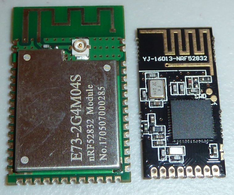
    Breakout board for the Ebyte nRF52832 module is now completed:
    https://www.openhardware.io/view/436/nRF52832-Breakout-Board#tabs-comments


  • @NeverDie Dam you why would you make it so wide? can it fit on a single bread board?

    Also how did you get those so fast?


  • Hero Member

    @Mike_Lemo said in nRF5 Bluetooth action!:

    Dam you why would you make it so wide?

    In 20/20 hindsight, you're right. At the time I designed it I had huge concerns that the range on the nRF52832 might be awful, because the Adafruit nRF52832 feather that I tested had poor range. So, I gave it a very large ground plane to see if maybe that cured the problem. Only later did I receive the Ebyte module, which turned out to have good range even by itself.

    can it fit on a single bread board?

    Sorry, you'll need two.

    Also how did you get those so fast?

    OSH PARK averages around two weeks for me. That's the main reason why I buy from them.


  • Hardware Contributor

    @NeverDie
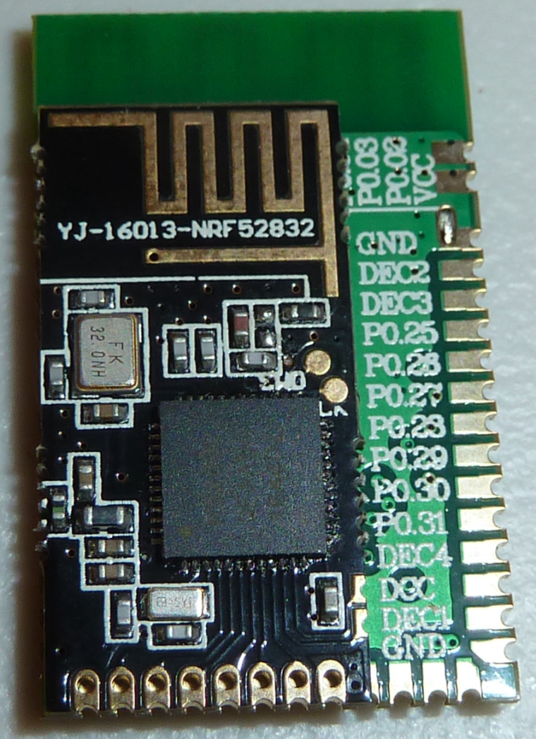
    Where did you get that small nrf52832 module?


  • Hero Member


  • Hardware Contributor

    @NeverDie I guess you don't need to make a breakout board for those, your spare NModules will do if you use the "PA/LNA" radio footprint 😉


  • Hero Member

    @Nca78
    Thanks! Good to know.


  • Hardware Contributor

    Just realized it has 2 extra I/O on the side, and the SWD are only pads on top, which makes 8 I/O available, it's much more interesting than the NRF51822 version.


  • Hero Member

    @Nca78
    Is there even a way to program the nRF51822 version? I'd have to check, but I don't recall the two SWD pins being on its pinout.


  • Hardware Contributor

    @NeverDie said in nRF5 Bluetooth action!:

    @Nca78
    Is there even a way to program the nRF51822 version? I'd have to check, but I don't recall the two SWD pins being on its pinout.

    They are on the pinout, so you only have 4 I/Os available.


  • Hero Member

    @d00616 said in nRF5 Bluetooth action!:

    I have tried the hwCPUVoltage() function with an Ebyte and an RedBear module. Both modules are reporting the voltage.

    That's good news. There must be something wrong with how I'm doing it. Which board type are you using for the Ebyte module?


  • From what I understand the NRF52832 has some kind of enforcer that allows different serial hardwares to be assigned to different pins

    Now using the arduino IDE I want to use the I2C pins that are assigned hardwarely to different pins here is the situation

    I have one PCB that has SCL connected to pin 20 and SDA to 21

    and another PCB that has SCL connected to pin 11 and SDA to pin 12

    I want to define the enforcer for the pins within their dedicated sketches without running around to the internal arduino files and change the pin assignment for each upload to each board.

    How'd I do that? I assume you'd have to do some thing like that in the upper side of the personal code.

    #define SDL...(Something else I don't know ) 11
    #define SDA...(Something else I don't know ) 12


  • Hero Member

    I think I have a better hypothesis as to what's going on in my situation: the ebyte module is getting hung-up trying to establish communication with the serial gateway. Looking at the output of the serial gateway, it looks as though it is receiving packets from the Ebyte module. However, looking at the Ebyte output, it thinks it is failing. So, the Ebyte never quite gets out of the "establish communication link" mode.

    This doesn't occur, though, if I use an nRF52 DK, instead of an Ebyte module.

    So, what might explain this is maybe the MISO pin on the Ebyte module isn't mapped right.

    @d00616 Would you please share the pin mappings and board type that you are using for your ebyte module? Since you are having success, I think that will fix the problem.


  • Does anybody know why the function tone() doesn't work for the nrf52?


  • Mod

    @Mike_Lemo could you be slightly more specific than "doesn't work"?


  • @mfalkvidd said in nRF5 Bluetooth action!:

    @Mike_Lemo could you be slightly more specific than "doesn't work"?

    apparently it doesn't recognize it says tone wasn't declared in this scope

    That's how the line looks tone(BUZZER_PIN, BUZZER_TONE);
    BUZZER_PIN = 26
    BUZZER_TONE = 3000


  • Mod

    @Mike_Lemo if you mean the stuff described at https://www.arduino.cc/en/Reference/Tone it's because it only supports the following mcus:
    ATmega8
    ATmega168/328
    ATmega1280


  • @mfalkvidd said in nRF5 Bluetooth action!:

    @Mike_Lemo if you mean the stuff described at https://www.arduino.cc/en/Reference/Tone it's because it only supports the following mcus:
    ATmega8
    ATmega168/328
    ATmega1280

    How is it possible to make it copatible with the NRF52?


  • Mod

    @Mike_Lemo it (the tone library) would need to be ported


  • @mfalkvidd said in nRF5 Bluetooth action!:

    @Mike_Lemo it would need to be ported

    No idea what you are talking about.


  • Mod


  • Hero Member

    @NeverDie said in nRF5 Bluetooth action!:

    I think I have a better hypothesis as to what's going on in my situation: the ebyte module is getting hung-up trying to establish communication with the serial gateway. Looking at the output of the serial gateway, it looks as though it is receiving packets from the Ebyte module. However, looking at the Ebyte output, it thinks it is failing. So, the Ebyte never quite gets out of the "establish communication link" mode.

    This doesn't occur, though, if I use an nRF52 DK, instead of an Ebyte module.

    So, what might explain this is maybe the MISO pin on the Ebyte module isn't mapped right.

    @d00616 Would you please share the pin mappings and board type that you are using for your ebyte module? Since you are having success, I think that will fix the problem.

    Some further evidence in support of this hypothesis (from: https://github.com/mysensors/ArduinoHwNRF5😞

    Most components, like UART, SPI, Wire Bus, of the nRF5 series chips don't have a fixed pin mapping.


  • @mfalkvidd said in nRF5 Bluetooth action!:

    @Mike_Lemo look it up? https://en.wikipedia.org/wiki/Software_portability#Effort_to_port_source_code

    Well apperantly this function uses a PWM pin at 50% duty but the frequency varies according to the functiong user parameter now I just know how to active a PWM pin at 50% duty but not how to acces the NRF52 registers to change the frequency of the PWM.

    I don't realy know how to access the registers you see at the product's PDF and the other process.


  • Someone managed to get NFC to work with this IC on the arduino IDE?


  • Hero Member

    Does the nRF52 mcu communicate with its radio using SPI, or some other bus? Or are all the radio registers simply memory mapped?

    @NeverDie said in nRF5 Bluetooth action!:

    Some further evidence in support of this hypothesis (from: https://github.com/mysensors/ArduinoHwNRF5😞

    Most components, like UART, SPI, Wire Bus, of the nRF5 series chips don't have a fixed pin mapping.

    Well, if the mcu uses SPI to communicate with the radio, then I simply need to define which SPI "pins" those are. Attached is the pin mapping file that I used to successfully map the pins for Rx and Tx.
    0_1501606355303_MyNRF5Board.cpp


  • Hardware Contributor

    @NeverDie if I'm not wrong you managed to connect the Ebyte module to your MySensors network, no ?
    I did it anyway and it received data.
    Radio is internally connected inside the nrf52 chip so I don't see how a module could have a different mapping ?


  • Hero Member

    @Nca78 said in nRF5 Bluetooth action!:

    Radio is internally connected inside the nrf52 chip so I don't see how a module could have a different mapping ?

    Yeah, that's what I thought originally, and it probably is true. I'm just grasping at straws to understand why the "board" type seems to be affecting the radio communications. I'm also completely new to the mysensors way of handling radio, so that's getting in my way. I'm might have to try something more barebones before I can make sense of this.


  • Some Nordic guidance might help.

    Building Bluetooth-Connected IoT Wireless Sensor Prototypes with Minimal Effort

    https://www.digikey.com/en/articles/techzone/2017/jul/building-bluetooth-connected-iot-wireless-sensor-prototypes


  • Hero Member

    I've confirmed it now. Even if I comment out all apparent radio message sends, the mere act of including:

    #include <MySensors.h>
    

    results in a loss of control by the sketch itself to something within MySensors that wants to establish communication between the node and the gateway. Not even sure how that is happening. In any case, it is just overcomplicating the debugging, and I really don't want that right now because it is effectively hanging what I'm trying to do. 😠

    For now, all I want is a simple send packet--like either the mirf or the twh20 libraries have for the nRF24L01--with no complicating factors. Is that too much to ask? I can probably find that somewhere within the library, but how do I turn-off this loop that it's in where it's repetitively trying to establish the initial communication with the serial gateway?


  • Contest Winner

    @NeverDie said in nRF5 Bluetooth action!:

    That's good news. There must be something wrong with how I'm doing it. Which board type are you using for the Ebyte module?

    I have the equal module like yours.

    @NeverDie said in nRF5 Bluetooth action!:

    @d00616 Would you please share the pin mappings and board type that you are using for your ebyte module? Since you are having success, I think that will fix the problem.

    The module is connected to SWDIO/CLK, VCC and the GND near the radio. I don't remember which pin I used for Serial TX.

    @NeverDie said in nRF5 Bluetooth action!:

    Does the nRF52 mcu communicate with its radio using SPI, or some other bus? Or are all the radio registers simply memory mapped?

    The registers are memory mapped, the data transferred with "EasyDMA" into the memory.

    @NeverDie said in nRF5 Bluetooth action!:

    I've confirmed it now. Even if I comment out all apparent radio message sends, the mere act of including: '#include <MySensors.h>' results in a loss of control by the sketch itself to something within MySensors that wants to establish communication between the node and the gateway.

    The SecurityPersonalizer defines '#define MY_CORE_ONLY' before including 'MySensors.h'. In theory, you can use the radio functions defined in 'hal/transport/MyTransportHAL.h' directly. I had no luck with this, but I haven't invested time to debug this.


  • Contest Winner

    @Mike_Lemo said in nRF5 Bluetooth action!:

    I want to define the enforcer for the pins within their dedicated sketches without running around to the internal arduino files and change the pin assignment for each upload to each board.
    How'd I do that? I assume you'd have to do some thing like that in the upper side of the personal code.
    #define SDL...(Something else I don't know ) 11
    #define SDA...(Something else I don't know ) 12

    You have to install the "MySensors nRF5 Boards" package. In the examples section for this package, you can find two files (MyNRF5Board.h + MyNRF5Board.cpp). Add these files to your sketch and compile it using "MyNRF5Board nRF52822" as you board.

    @Mike_Lemo said in nRF5 Bluetooth action!:

    Well apperantly this function uses a PWM pin at 50% duty but the frequency varies according to the functiong user parameter now I just know how to active a PWM pin at 50% duty but not how to acces the NRF52 registers to change the frequency of the PWM.

    The registers are documented in the Infocenter and the bitfields.

    I don't realy know how to access the registers you see at the product's PDF and the other process.

    To access the registers, you have to add '#include <nrf.h>' to your code. Mostly the hardware is accesses by NRF_HWNAME->REGISTER

    Doing PWM is a little bit complex. The code is different for nRF51 and nRF52. Look into wiring_analog_nRF51.c and (wiring_analog_nRF51.c)[https://github.com/sandeepmistry/arduino-nRF5/blob/c98a190eb34c0247eb8e0764a6367c7f9e51d2fc/cores/nRF5/wiring_analog_nRF52.c#L214]

    If you clone this code, for nRF52 you have to use another timer, like TIMER2, because you can't define the interrupt routine twice.


  • Hardware Contributor

    So I'm trying to program the S4AT modules and I have the ugly message

    ** Programming Started **
    auto erase enabled
    Info : nRF51822-QFAA(build code: H0) 256kB Flash
    Error: Cannot erase protected sector at 0x0
    Error: failed erasing sectors 0 to 13
    embedded:startup.tcl:454: Error: ** Programming Failed **
    

    I tried to use JLink programs but it says it cannot connect to the module, so I cannot unlock (ends with timeout message) and I cannot erase (fails with -1 return value)...
    Does that mean I have to go the long hard way with a bluepill as programmer and openocd ? Anyone has other ideas to unlock and erase the device ?


  • Contest Winner

    @Nca78 said in nRF5 Bluetooth action!:

    Does that mean I have to go the long hard way with a bluepill as programmer and openocd ? Anyone has other ideas to unlock and erase the device ?

    Select in to Tools menu "None" Softdevice and then "Burn Bootloader". This raises an error but the device is erased completely.


  • Hardware Contributor

    @d00616 said in nRF5 Bluetooth action!:

    Select in to Tools menu "None" Softdevice and then "Burn Bootloader". This raises an error but the device is erased completely.

    Thank you it works ! ❤ ❤ ❤
    That's probably when trying to use this function that I managed to unlock&erase the EByte module "by mistake" 🙂

    The only problem now is the range seems to be very bad 😞
    Less than 10m with just a brick wall and it fails to completely send the presentation messages.
    EBytes nrf52832 module works well in the same conditions, same for their nrf24 modules.

    [Edit] in fact not that bad, it works ok when changing the orientation of the module. Could be due to the funky wiring but my bet is it on the tiny antenna design. My gateway is an old through hole nrf24 clone so range should not be a problem in an appartment with a PA/LNA gateway.


  • Hero Member

    @d00616 said in nRF5 Bluetooth action!:

    The registers are memory mapped, the data transferred with "EasyDMA" into the memory.

    In this case I'm going to try a different Ebyte module. Maybe the one I'm using is defective or somehow became damaged.


  • Hero Member

    @d00616 said in nRF5 Bluetooth action!:

    Select in to Tools menu "None" Softdevice and then "Burn Bootloader". This raises an error but the device is erased completely.

    I'm happy to report this also worked when, just now, I programmed a new Ebyte module. Like d00616 said earlier, it's a much faster way to do a mass erase. 🙂

    Unfortunately, and in contrast with the nRF52 DK, the new Ebyte module I just programmed is behaving the same as the Ebyte I've been experimenting with. No change.


  • Hardware Contributor

    I will test tomorrow with the Ebyte module I have soldered, and the reset pin too.


  • @d00616 said in nRF5 Bluetooth action!:

    MySensors nRF5 Boards

    Thanks for the caring replay.

    I couldn't find that exact "MySensors nRF5 Boards" library you were talking about also what is the purpose of this library anyways?

    Do you know where can the arduino library folder be found with all the arduino functions?


  • Hardware Contributor

    @Mike_Lemo it is here :
    https://github.com/mysensors/ArduinoHwNRF5

    Scroll up in this thread for more details, or read the documentation there.


  • Contest Winner

    @Mike_Lemo said in nRF5 Bluetooth action!:

    I couldn't find that exact "MySensors nRF5 Boards" library you were talking about also what is the purpose of this library anyways?

    Follow the instructions for ArduinoBoards and ArduinoHwNRF5

    Do you know where can the arduino library folder be found with all the arduino functions?

    The arduino-nrf5 port only implements functionality documented in the official Arduino Reference but mostly not more functionality available for SAMD :-(. Additional functionality like BLE or using included hardware must come from external libraries like MySensors.

    A good way to implement the tone commands is to fork the arduino-nRF5 repository at github. Change what you need and create an pull request with reference to the Arduino reference. If you inform me about your PR I comment it to increase the chance for acceptance otherwise it's time to maintain an separate fork of this repository.


  • Hero Member

    @Nca78 said in nRF5 Bluetooth action!:

    I will test tomorrow with the Ebyte module I have soldered, and the reset pin too.

    That would be great! 🙂 Please try the BatteryPoweredSensor sketch when you do. I'm very curious if you will have the same or different result as what I'm getting.


  • @d00616 said in nRF5 Bluetooth action!:

    @Mike_Lemo said in nRF5 Bluetooth action!:

    I couldn't find that exact "MySensors nRF5 Boards" library you were talking about also what is the purpose of this library anyways?

    Follow the instructions for ArduinoBoards and ArduinoHwNRF5

    Do you know where can the arduino library folder be found with all the arduino functions?

    The arduino-nrf5 port only implements functionality documented in the official Arduino Reference but mostly not more functionality available for SAMD :-(. Additional functionality like BLE or using included hardware must come from external libraries like MySensors.

    A good way to implement the tone commands is to fork the arduino-nRF5 repository at github. Change what you need and create an pull request with reference to the Arduino reference. If you inform me about your PR I comment it to increase the chance for acceptance otherwise it's time to maintain an separate fork of this repository.

    that actually caused more trouble won't even let me compile the blank included example code.


  • Hero Member

    @Mike_Lemo said in nRF5 Bluetooth action!:

    that actually caused more trouble won't even let me compile the blank included example code.

    Are you talking about the MyNRF5Board example? Arduino IDE compiles it for me without any complaints.


  • @NeverDie When choosing "MyNRF5Board nrf52832"?


  • Hero Member

    @Mike_Lemo said in nRF5 Bluetooth action!:

    @NeverDie When choosing "MyNRF5Board nrf52832"?

    Yup.


  • Hero Member

    At some point, I had to re-arrange the libraries though (don't remember which files or which ones) to get all this stuff working. Before that, it wasn't finding the files. Actually, I think this would be a good topic for discussion, to make sure we're all doing it the same way. If we're doing it differently, it might make cross-checking each others attempts more difficult. Also, maybe there's a better way than the brute-force way that I did it.

    If anyone has interest, I can post how my libraries are currently structured. If nothing else, it would be a starting point for discussion on what to do (or not to do).


  • @NeverDie said in nRF5 Bluetooth action!:

    At some point, I had to re-arrange the libraries though (don't remember which files or which ones) to get all this stuff working. Before that, it wasn't finding the files. Actually, I think this would be a good topic for discussion, to make sure we're all doing it the same way. If we're doing it differently, it might make cross-checking each others attempts more difficult. Also, maybe there's a better way than the brute-force way that I did it.

    If anyone has interest, I can post how my libraries are currently structured. If nothing else, it would be a starting point for discussion on what to do (or not to do).

    Dunno that whole arduino BRF52832 programming thing seems too complicated just started to learn how to use the nordic SDK with eclipse until a proper solution is found.


  • Hero Member

    @Mike_Lemo said in nRF5 Bluetooth action!:

    Dunno that whole arduino BRF52832 programming thing seems too complicated just started to learn how to use the nordic SDK with eclipse until a proper solution is found.

    It hasn't been easy, I'll grant you that. I get the impression d00616 probably does most of his work in Linux, and so some of the disconnect with the Windows IDE probably stems from that. Once we get the basics ironed out, though, I expect things will go more smoothly. In fact, I think we're almost there. A lot of the work for sleeping, measuring source voltage, etc., has already been done, which is far better than starting from scratch. And there's even example code, which helps tremendously.


  • Hero Member

    Good news! Interestingly enough, the MockMySensors sketch seems to work fine when I load it onto the Ebyte. What a relief! So, I may try hijacking that sketch to convey voltage measurements instead of the BatteryPoweredSensor sketch that mysteriously hasn't been working on my Ebyte modules.


  • Contest Winner

    @Mike_Lemo said in nRF5 Bluetooth action!:

    Dunno that whole arduino BRF52832 programming thing seems too complicated just started to learn how to use the nordic SDK with eclipse until a proper solution is found.

    The Nordic SDK is more complete than Arduino-nrf5 at the moment, but there is no compatibility with MySensors.

    The good news, with SDK 13 the 'Nordic Semiconductor ASA' License was changed. The old ASA was the reason for me to rewrite the complete ESB protocol. Now the license is much less restrictive. I think now the way is open to integrate SDK code into arduino-nrf5 or provide SDK based arduino-libraries.

    @NeverDie said in nRF5 Bluetooth action!:

    It hasn't been easy, I'll grant you that. I get the impression d00616 probably does most of his work in Linux, and so some of the disconnect with the Windows IDE probably stems from that.

    I can't change the way of Windows driver handling, but when there are Windows specific issues then they bust be fixed.


  • @d00616 said in nRF5 Bluetooth action!:

    @Mike_Lemo said in nRF5 Bluetooth action!:

    Dunno that whole arduino BRF52832 programming thing seems too complicated just started to learn how to use the nordic SDK with eclipse until a proper solution is found.

    The Nordic SDK is more complete than Arduino-nrf5 at the moment, but there is no compatibility with MySensors.

    The good news, with SDK 13 the 'Nordic Semiconductor ASA' License was changed. The old ASA was the reason for me to rewrite the complete ESB protocol. Now the license is much less restrictive. I think now the way is open to integrate SDK code into arduino-nrf5 or provide SDK based arduino-libraries.

    .

    You mean way more complete every thing is accesable there and there is an example for everything and I didn't use my sensors anyways


  • Contest Winner

    @Mike_Lemo said in nRF5 Bluetooth action!:

    You mean way more complete every thing is accesable there and there is an example for everything and I didn't use my sensors anyways

    No. I mean if you want to use the Nordic MCU with BLE and you want to access the whole hardware without developing drivers, then the Nordic SDK is an option. For special requirements like tone() you have to develop your own routine for Arduino or SDK.

    If you want write code which is compatible with other Vendors or want use MySensors then the SDK isn't the best choice.

    The arduino-nrf5 targets to provide the Arduino language. I think this is mostly complete. MySensors brings additional support for enhanced pin output modes and the random number generator (no SoftDevice support here).

    Accessing the internal MCU hardware must be added via Arduino libraries. With the new SDK license I think it's possible to put parts of the SDK into libraries supporting Hardware which is not specified in the Arduino reference.

    If you want to develop BLE applications with portable code, there are open source implementations like http://mynewt.apache.org/ which are designed to be portable.


  • Hero Member

    Good news! The hwCPUVoltage() function measures the Vcc voltage on the Ebyte module in millivolts. I'm able to send that as a barometer reading using the mocksensors sketch, and it arrives all the way into Domoticz, where it is logged and graphed. So, obviously I need to streamline that a bit, but the proof of concept works. 🙂


Log in to reply
 

Suggested Topics

  • 8
  • 29
  • 1
  • 1
  • 2
  • 2

0
Online

11.2k
Users

11.1k
Topics

112.5k
Posts