Battery percentage on door contact sensor erratic (sent on interrupt)
-
Ok so I have 3 Temp sensors that display battery percentage pretty well and sleep for 5 minutes between reads.
Now through research on the forum I have put together a sketch for a door sensor that sleeps until interrupted and sends the battery percentage .
The problem I have is that the battery percentage varies with every read this is the serial monitor read:3430 TSF:TDI:TSL 3432 MCO:SLP:WUP=-1 3436 TSF:TRI:TSB 3436 MCO:SLP:MS=0,SMS=0,I1=1,M1=1,I2=255,M2=255 3442 TSF:TDI:TSL 3444 MCO:SLP:WUP=1 3446 TSF:TRI:TSB Sensor value: 832 Battery Voltage: 2.68 V Battery percent: -2 % 3452 TSF:MSG:SEND,4-4-0-0,s=255,c=3,t=0,pt=1,l=1,sg=0,ft=0,st=OK:254 3463 TSF:MSG:SEND,4-4-0-0,s=3,c=1,t=16,pt=2,l=2,sg=0,ft=0,st=OK:1 Tripped3471 MCO:SLP:MS=5,SMS=0,I1=255,M1=255,I2=255,M2=255 3475 TSF:TDI:TSL 3477 MCO:SLP:WUP=-1 3479 TSF:TRI:TSB 3481 MCO:SLP:MS=0,SMS=0,I1=1,M1=1,I2=255,M2=255 3487 TSF:TDI:TSL 3489 MCO:SLP:WUP=1 3491 TSF:TRI:TSB Sensor value: 953 Battery Voltage: 3.07 V Battery percent: 62 % 3497 TSF:MSG:SEND,4-4-0-0,s=255,c=3,t=0,pt=1,l=1,sg=0,ft=0,st=OK:62 3508 TSF:MSG:SEND,4-4-0-0,s=3,c=1,t=16,pt=2,l=2,sg=0,ft=0,st=OK:0 Tripped3514 MCO:SLP:MS=5,SMS=0,I1=255,M1=255,I2=255,M2=255 3520 TSF:TDI:TSL 3522 MCO:SLP:WUP=-1 3524 TSF:TRI:TSB 3526 MCO:SLP:MS=0,SMS=0,I1=1,M1=1,I2=255,M2=255 3532 TSF:TDI:TSL 3534 MCO:SLP:WUP=1 3536 TSF:TRI:TSB Sensor value: 930 Battery Voltage: 3.00 V Battery percent: 50 % 3543 TSF:MSG:SEND,4-4-0-0,s=255,c=3,t=0,pt=1,l=1,sg=0,ft=0,st=OK:50 3553 TSF:MSG:SEND,4-4-0-0,s=3,c=1,t=16,pt=2,l=2,sg=0,ft=0,st=OK:1 Tripped3559 MCO:SLP:MS=5,SMS=0,I1=255,M1=255,I2=255,M2=255 3565 TSF:TDI:TSL 3567 MCO:SLP:WUP=-1 3569 TSF:TRI:TSB 3571 MCO:SLP:MS=0,SMS=0,I1=1,M1=1,I2=255,M2=255 3575 TSF:TDI:TSL 3577 MCO:SLP:WUP=1 3579 TSF:TRI:TSB Sensor value: 854 Battery Voltage: 2.75 V Battery percent: 9 % 3586 TSF:MSG:SEND,4-4-0-0,s=255,c=3,t=0,pt=1,l=1,sg=0,ft=0,st=OK:9 3596 TSF:MSG:SEND,4-4-0-0,s=3,c=1,t=16,pt=2,l=2,sg=0,ft=0,st=OK:0 Tripped3604 MCO:SLP:MS=5,SMS=0,I1=255,M1=255,I2=255,M2=255```and this is the sketch;
/**
 * The MySensors Arduino library handles the wireless radio link and protocol
 * between your home built sensors/actuators and HA controller of choice.
 * The sensors forms a self healing radio network with optional repeaters. Each
 * repeater and gateway builds a routing tables in EEPROM which keeps track of the
 * network topology allowing messages to be routed to nodes.
 *
 * Created by Henrik Ekblad <henrik.ekblad@mysensors.org>
 * Copyright (C) 2013-2015 Sensnology AB
 * Full contributor list: https://github.com/mysensors/Arduino/graphs/contributors
 *
 * Documentation: http://www.mysensors.org
 * Support Forum: http://forum.mysensors.org
 *
 * This program is free software; you can redistribute it and/or
 * modify it under the terms of the GNU General Public License
 * version 2 as published by the Free Software Foundation.
 *
 *******************************
 *
 * DESCRIPTION
 *
 * Simple binary switch example
 * Connect button or door/window reed switch between
 * digitial I/O pin 3 (BUTTON_PIN below) and GND.
 * http://www.mysensors.org/build/binary
 */


// Enable debug prints to serial monitor
#define MY_DEBUG

// Enable and select radio type attached
#define MY_RADIO_NRF24
//#define MY_RADIO_RFM69

#define MY_NODE_ID 4

#include <SPI.h>
#include <MySensors.h>


#define CHILD_ID 3
#define BUTTON_PIN  3  // Arduino Digital I/O pin for button/reed switch

#define SLEEP_TIME 0 // sleep forever

// Change to V_LIGHT if you use S_LIGHT in presentation below
MyMessage msg(CHILD_ID,V_TRIPPED);

// ------------------ BATTERY ------------------
int BATTERY_SENSE_PIN = A0;  // select the input pin for the battery sense point
int oldBatteryPcnt = 0;  // remember last measured percentage
#define V_MIN 2.7  // 0% Battery voltage
#define V_MAX 3.3  // 100% Battery voltage

byte oldSwitch_State = HIGH;


void setup()
{
  // Setup the button
  pinMode(BUTTON_PIN,INPUT);
  // Activate internal pull-up
  digitalWrite(BUTTON_PIN,HIGH);


  // Setup 1.1 V internal reference for analoge GPIO
  analogReference(INTERNAL);

}

void presentation() {
  // Register binary input sensor to gw (they will be created as child devices)
  // You can use S_DOOR, S_MOTION or S_LIGHT here depending on your usage.
  // If S_LIGHT is used, remember to update variable type you send in. See "msg" above.
  present(CHILD_ID, S_DOOR);
}


//  Check if digital input has changed and send in new value
void loop()
{
  // read analog pin
  int sensorValue = analogRead(BATTERY_SENSE_PIN);
  // calculate battery voltage
  float vBat  = static_cast<float>(sensorValue * (V_MAX/1023));
  // calculate % left of defined interval
  int batteryPcnt = static_cast<int>(((vBat-V_MIN)/(V_MAX-V_MIN))*100.);
  // debugging
  #ifdef MY_DEBUG
    Serial.print("Sensor value: ");
    Serial.println(sensorValue);
    Serial.print("Battery Voltage: ");
    Serial.print(vBat);
    Serial.println(" V");
    Serial.print("Battery percent: ");
    Serial.print(batteryPcnt);
    Serial.println(" %");
  #endif
  // If battery % has change send to controller
  if (oldBatteryPcnt != batteryPcnt) {
    // Power up radio after sleep
    sendBatteryLevel(batteryPcnt);
    oldBatteryPcnt = batteryPcnt;

  }
{

 {

   byte switchState = digitalRead (BUTTON_PIN);


  if (switchState != oldSwitch_State) {
     // Send in the new value
     send(msg.set(switchState==LOW ? 1 : 0));
     oldSwitch_State = switchState;

     sleep(5);
  }


 sleep(digitalPinToInterrupt(BUTTON_PIN), CHANGE, SLEEP_TIME);
}
}
}
I have the resistors set up as described here
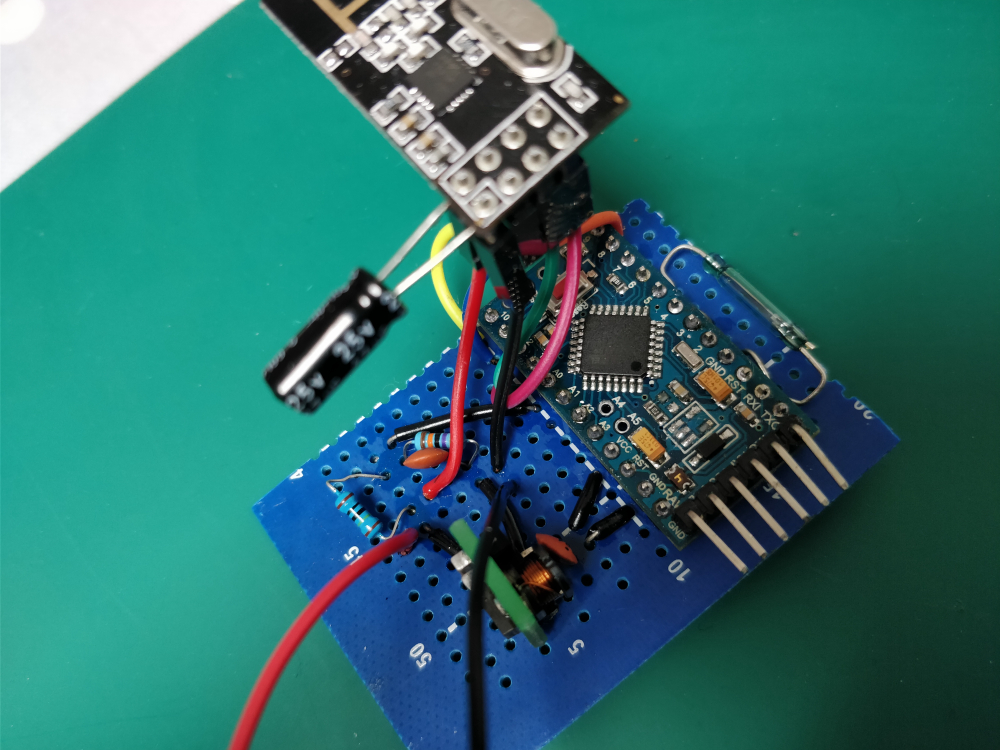
with the addition of a 0.1uF cap over R2 (470KΩ) resistoris there a way to stabilize these readings ?
-
Ok so I have 3 Temp sensors that display battery percentage pretty well and sleep for 5 minutes between reads.
Now through research on the forum I have put together a sketch for a door sensor that sleeps until interrupted and sends the battery percentage .
The problem I have is that the battery percentage varies with every read this is the serial monitor read:3430 TSF:TDI:TSL 3432 MCO:SLP:WUP=-1 3436 TSF:TRI:TSB 3436 MCO:SLP:MS=0,SMS=0,I1=1,M1=1,I2=255,M2=255 3442 TSF:TDI:TSL 3444 MCO:SLP:WUP=1 3446 TSF:TRI:TSB Sensor value: 832 Battery Voltage: 2.68 V Battery percent: -2 % 3452 TSF:MSG:SEND,4-4-0-0,s=255,c=3,t=0,pt=1,l=1,sg=0,ft=0,st=OK:254 3463 TSF:MSG:SEND,4-4-0-0,s=3,c=1,t=16,pt=2,l=2,sg=0,ft=0,st=OK:1 Tripped3471 MCO:SLP:MS=5,SMS=0,I1=255,M1=255,I2=255,M2=255 3475 TSF:TDI:TSL 3477 MCO:SLP:WUP=-1 3479 TSF:TRI:TSB 3481 MCO:SLP:MS=0,SMS=0,I1=1,M1=1,I2=255,M2=255 3487 TSF:TDI:TSL 3489 MCO:SLP:WUP=1 3491 TSF:TRI:TSB Sensor value: 953 Battery Voltage: 3.07 V Battery percent: 62 % 3497 TSF:MSG:SEND,4-4-0-0,s=255,c=3,t=0,pt=1,l=1,sg=0,ft=0,st=OK:62 3508 TSF:MSG:SEND,4-4-0-0,s=3,c=1,t=16,pt=2,l=2,sg=0,ft=0,st=OK:0 Tripped3514 MCO:SLP:MS=5,SMS=0,I1=255,M1=255,I2=255,M2=255 3520 TSF:TDI:TSL 3522 MCO:SLP:WUP=-1 3524 TSF:TRI:TSB 3526 MCO:SLP:MS=0,SMS=0,I1=1,M1=1,I2=255,M2=255 3532 TSF:TDI:TSL 3534 MCO:SLP:WUP=1 3536 TSF:TRI:TSB Sensor value: 930 Battery Voltage: 3.00 V Battery percent: 50 % 3543 TSF:MSG:SEND,4-4-0-0,s=255,c=3,t=0,pt=1,l=1,sg=0,ft=0,st=OK:50 3553 TSF:MSG:SEND,4-4-0-0,s=3,c=1,t=16,pt=2,l=2,sg=0,ft=0,st=OK:1 Tripped3559 MCO:SLP:MS=5,SMS=0,I1=255,M1=255,I2=255,M2=255 3565 TSF:TDI:TSL 3567 MCO:SLP:WUP=-1 3569 TSF:TRI:TSB 3571 MCO:SLP:MS=0,SMS=0,I1=1,M1=1,I2=255,M2=255 3575 TSF:TDI:TSL 3577 MCO:SLP:WUP=1 3579 TSF:TRI:TSB Sensor value: 854 Battery Voltage: 2.75 V Battery percent: 9 % 3586 TSF:MSG:SEND,4-4-0-0,s=255,c=3,t=0,pt=1,l=1,sg=0,ft=0,st=OK:9 3596 TSF:MSG:SEND,4-4-0-0,s=3,c=1,t=16,pt=2,l=2,sg=0,ft=0,st=OK:0 Tripped3604 MCO:SLP:MS=5,SMS=0,I1=255,M1=255,I2=255,M2=255```and this is the sketch;
/**
 * The MySensors Arduino library handles the wireless radio link and protocol
 * between your home built sensors/actuators and HA controller of choice.
 * The sensors forms a self healing radio network with optional repeaters. Each
 * repeater and gateway builds a routing tables in EEPROM which keeps track of the
 * network topology allowing messages to be routed to nodes.
 *
 * Created by Henrik Ekblad <henrik.ekblad@mysensors.org>
 * Copyright (C) 2013-2015 Sensnology AB
 * Full contributor list: https://github.com/mysensors/Arduino/graphs/contributors
 *
 * Documentation: http://www.mysensors.org
 * Support Forum: http://forum.mysensors.org
 *
 * This program is free software; you can redistribute it and/or
 * modify it under the terms of the GNU General Public License
 * version 2 as published by the Free Software Foundation.
 *
 *******************************
 *
 * DESCRIPTION
 *
 * Simple binary switch example
 * Connect button or door/window reed switch between
 * digitial I/O pin 3 (BUTTON_PIN below) and GND.
 * http://www.mysensors.org/build/binary
 */


// Enable debug prints to serial monitor
#define MY_DEBUG

// Enable and select radio type attached
#define MY_RADIO_NRF24
//#define MY_RADIO_RFM69

#define MY_NODE_ID 4

#include <SPI.h>
#include <MySensors.h>


#define CHILD_ID 3
#define BUTTON_PIN  3  // Arduino Digital I/O pin for button/reed switch

#define SLEEP_TIME 0 // sleep forever

// Change to V_LIGHT if you use S_LIGHT in presentation below
MyMessage msg(CHILD_ID,V_TRIPPED);

// ------------------ BATTERY ------------------
int BATTERY_SENSE_PIN = A0;  // select the input pin for the battery sense point
int oldBatteryPcnt = 0;  // remember last measured percentage
#define V_MIN 2.7  // 0% Battery voltage
#define V_MAX 3.3  // 100% Battery voltage

byte oldSwitch_State = HIGH;


void setup()
{
  // Setup the button
  pinMode(BUTTON_PIN,INPUT);
  // Activate internal pull-up
  digitalWrite(BUTTON_PIN,HIGH);


  // Setup 1.1 V internal reference for analoge GPIO
  analogReference(INTERNAL);

}

void presentation() {
  // Register binary input sensor to gw (they will be created as child devices)
  // You can use S_DOOR, S_MOTION or S_LIGHT here depending on your usage.
  // If S_LIGHT is used, remember to update variable type you send in. See "msg" above.
  present(CHILD_ID, S_DOOR);
}


//  Check if digital input has changed and send in new value
void loop()
{
  // read analog pin
  int sensorValue = analogRead(BATTERY_SENSE_PIN);
  // calculate battery voltage
  float vBat  = static_cast<float>(sensorValue * (V_MAX/1023));
  // calculate % left of defined interval
  int batteryPcnt = static_cast<int>(((vBat-V_MIN)/(V_MAX-V_MIN))*100.);
  // debugging
  #ifdef MY_DEBUG
    Serial.print("Sensor value: ");
    Serial.println(sensorValue);
    Serial.print("Battery Voltage: ");
    Serial.print(vBat);
    Serial.println(" V");
    Serial.print("Battery percent: ");
    Serial.print(batteryPcnt);
    Serial.println(" %");
  #endif
  // If battery % has change send to controller
  if (oldBatteryPcnt != batteryPcnt) {
    // Power up radio after sleep
    sendBatteryLevel(batteryPcnt);
    oldBatteryPcnt = batteryPcnt;

  }
{

 {

   byte switchState = digitalRead (BUTTON_PIN);


  if (switchState != oldSwitch_State) {
     // Send in the new value
     send(msg.set(switchState==LOW ? 1 : 0));
     oldSwitch_State = switchState;

     sleep(5);
  }


 sleep(digitalPinToInterrupt(BUTTON_PIN), CHANGE, SLEEP_TIME);
}
}
}
I have the resistors set up as described here
with the addition of a 0.1uF cap over R2 (470KΩ) resistoris there a way to stabilize these readings ?
@greymarvel what happens if you place a sleep of e.g. 100ms just before reading the analog value?
Or write the analog reference every time just before the analog read?
You could also use my Vcc library as a reference: https://github.com/Yveaux/Arduino_Vcc
-
@greymarvel what happens if you place a sleep of e.g. 100ms just before reading the analog value?
Or write the analog reference every time just before the analog read?
You could also use my Vcc library as a reference: https://github.com/Yveaux/Arduino_Vcc
Ok so I added the analog reference into the loop and a delay(100);
this has improved things the readings are less erratic but still not close enough .2328 MCO:SLP:WUP=-1 2330 TSF:TRI:TSB 2332 MCO:SLP:MS=0,SMS=0,I1=1,M1=1,I2=255,M2=255 2336 TSF:TDI:TSL 2338 MCO:SLP:WUP=1 2340 TSF:TRI:TSB Sensor value: 876 Battery Voltage: 2.83 V Battery percent: 20 % 2447 TSF:MSG:SEND,4-4-0-0,s=255,c=3,t=0,pt=1,l=1,sg=0,ft=0,st=OK:20 2457 TSF:MSG:SEND,4-4-0-0,s=3,c=1,t=16,pt=2,l=2,sg=0,ft=0,st=OK:0 2465 MCO:SLP:MS=5,SMS=0,I1=255,M1=255,I2=255,M2=255 2469 TSF:TDI:TSL 2471 MCO:SLP:WUP=-1 2476 TSF:TRI:TSB 2476 MCO:SLP:MS=0,SMS=0,I1=1,M1=1,I2=255,M2=255 2482 TSF:TDI:TSL 2484 MCO:SLP:WUP=1 2486 TSF:TRI:TSB Sensor value: 874 Battery Voltage: 2.82 V Battery percent: 19 % 2594 TSF:MSG:SEND,4-4-0-0,s=255,c=3,t=0,pt=1,l=1,sg=0,ft=0,st=OK:19 2603 TSF:MSG:SEND,4-4-0-0,s=3,c=1,t=16,pt=2,l=2,sg=0,ft=0,st=OK:1 2611 MCO:SLP:MS=5,SMS=0,I1=255,M1=255,I2=255,M2=255 2617 TSF:TDI:TSL 2619 MCO:SLP:WUP=-1 2621 TSF:TRI:TSB 2623 MCO:SLP:MS=0,SMS=0,I1=1,M1=1,I2=255,M2=255 2627 TSF:TDI:TSL 2629 MCO:SLP:WUP=1 2631 TSF:TRI:TSB Sensor value: 854 Battery Voltage: 2.75 V Battery percent: 9 % 2738 TSF:MSG:SEND,4-4-0-0,s=255,c=3,t=0,pt=1,l=1,sg=0,ft=0,st=OK:9 2748 TSF:MSG:SEND,4-4-0-0,s=3,c=1,t=16,pt=2,l=2,sg=0,ft=0,st=OK:0 2754 MCO:SLP:MS=5,SMS=0,I1=255,M1=255,I2=255,M2=255 2760 TSF:TDI:TSL 2762 MCO:SLP:WUP=-1 2764 TSF:TRI:TSB 2766 MCO:SLP:MS=0,SMS=0,I1=1,M1=1,I2=255,M2=255 2772 TSF:TDI:TSL 2775 MCO:SLP:WUP=1 2777 TSF:TRI:TSB Sensor value: 853 Battery Voltage: 2.75 V Battery percent: 8 % 2883 TSF:MSG:SEND,4-4-0-0,s=255,c=3,t=0,pt=1,l=1,sg=0,ft=0,st=OK:8 2891 TSF:MSG:SEND,4-4-0-0,s=3,c=1,t=16,pt=2,l=2,sg=0,ft=0,st=OK:1 2899 MCO:SLP:MS=5,SMS=0,I1=255,M1=255,I2=255,M2=255 2906 TSF:TDI:TSL 2908 MCO:SLP:WUP=-1 2910 TSF:TRI:TSB 2912 MCO:SLP:MS=0,SMS=0,I1=1,M1=1,I2=255,M2=255 2916 TSF:TDI:TSL 2918 MCO:SLP:WUP=1 2920 TSF:TRI:TSB Sensor value: 852 Battery Voltage: 2.75 V Battery percent: 8 % 3026 TSF:MSG:SEND,4-4-0-0,s=3,c=1,t=16,pt=2,l=2,sg=0,ft=0,st=OK:0 3035 MCO:SLP:MS=5,SMS=0,I1=255,M1=255,I2=255,M2=255 3041 TSF:TDI:TSL 3043 MCO:SLP:WUP=-1 3045 TSF:TRI:TSB 3047 MCO:SLP:MS=0,SMS=0,I1=1,M1=1,I2=255,M2=255 3051 TSF:TDI:TSL 3053 MCO:SLP:WUP=1 3055 TSF:TRI:TSB Sensor value: 873 Battery Voltage: 2.82 V Battery percent: 19 % 3162 TSF:MSG:SEND,4-4-0-0,s=255,c=3,t=0,pt=1,l=1,sg=0,ft=0,st=OK:19 3172 TSF:MSG:SEND,4-4-0-0,s=3,c=1,t=16,pt=2,l=2,sg=0,ft=0,st=OK:1 3178 MCO:SLP:MS=5,SMS=0,I1=255,M1=255,I2=255,M2=255 3184 TSF:TDI:TSL 3186 MCO:SLP:WUP=-1 3188 TSF:TRI:TSB 3190 MCO:SLP:MS=0,SMS=0,I1=1,M1=1,I2=255,M2=255 3196 TSF:TDI:TSL 3196 MCO:SLP:WUP=1 3201 TSF:TRI:TSB Sensor value: 885 Battery Voltage: 2.85 V Battery percent: 25 % 3307 TSF:MSG:SEND,4-4-0-0,s=255,c=3,t=0,pt=1,l=1,sg=0,ft=0,st=OK:25 3315 TSF:MSG:SEND,4-4-0-0,s=3,c=1,t=16,pt=2,l=2,sg=0,ft=0,st=OK:0 3323 MCO:SLP:MS=5,SMS=0,I1=255,M1=255,I2=255,M2=255 3330 TSF:TDI:TSL 3332 MCO:SLP:WUP=-1 3334 TSF:TRI:TSB 3336 MCO:SLP:MS=0,SMS=0,I1=1,M1=1,I2=255,M2=255 3340 TSF:TDI:TSL 3342 MCO:SLP:WUP=1 3344 TSF:TRI:TSB Sensor value: 872 Battery Voltage: 2.81 V Battery percent: 18 % 3450 TSF:MSG:SEND,4-4-0-0,s=255,c=3,t=0,pt=1,l=1,sg=0,ft=0,st=OK:18 3461 TSF:MSG:SEND,4-4-0-0,s=3,c=1,t=16,pt=2,l=2,sg=0,ft=0,st=OK:1 3467 MCO:SLP:MS=5,SMS=0,I1=255,M1=255,I2=255,M2=255 3473 TSF:TDI:TSL 3475 MCO:SLP:WUP=-1 3477 TSF:TRI:TSB 3479 MCO:SLP:MS=0,SMS=0,I1=1,M1=1,I2=255,M2=255 3485 TSF:TDI:TSL 3487 MCO:SLP:WUP=1 3489 TSF:TRI:TSB Sensor value: 869 Battery Voltage: 2.80 V Battery percent: 17 % 3596 TSF:MSG:SEND,4-4-0-0,s=255,c=3,t=0,pt=1,l=1,sg=0,ft=0,st=OK:17 3604 TSF:MSG:SEND,4-4-0-0,s=3,c=1,t=16,pt=2,l=2,sg=0,ft=0,st=OK:0 3612 MCO:SLP:MS=5,SMS=0,I1=255,M1=255,I2=255,M2=255 3618 TSF:TDI:TSL 3620 MCO:SLP:WUP=-1 3622 TSF:TRI:TSB 3624 MCO:SLP:MS=0,SMS=0,I1=1,M1=1,I2=255,M2=255 3629 TSF:TDI:TSL 3631 MCO:SLP:WUP=1 3633 TSF:TRI:TSB``` -
@greymarvel what kind of battery are You using ? The voltage on the battery may not be constant in short periods, it depends on the load and bettery internal resistance. The higher the internal resistance the bigger are voltage swings in response to load swings. I have two identical boards, differing only in the batery holder, one is for cr2032 (higher internal resistance) and the other is for cr123 (lower internal resistance). These boards have exactyl the same circuit and software, the only difference is the battery type. And the one with cr2032 give me very unstable battery voltage readings while the other very is stable. So for sure it depends on the battery type and the current consumption at the moment of voltage probing.
-
@greymarvel what kind of battery are You using ? The voltage on the battery may not be constant in short periods, it depends on the load and bettery internal resistance. The higher the internal resistance the bigger are voltage swings in response to load swings. I have two identical boards, differing only in the batery holder, one is for cr2032 (higher internal resistance) and the other is for cr123 (lower internal resistance). These boards have exactyl the same circuit and software, the only difference is the battery type. And the one with cr2032 give me very unstable battery voltage readings while the other very is stable. So for sure it depends on the battery type and the current consumption at the moment of voltage probing.
@rozpruwacz I'm using 2 AA batteries . I think it might be worthwhile me using @Yveaux vcc library as a reference and see if that improves things. Also I think I might delay a little longer before the read to allow it to settle more after the contact interrupt .
-
@rozpruwacz I'm using 2 AA batteries . I think it might be worthwhile me using @Yveaux vcc library as a reference and see if that improves things. Also I think I might delay a little longer before the read to allow it to settle more after the contact interrupt .
@greymarvel AA batteries should have much lower internal resistance, so I guess that voltage reading should be stable. Good luck finding the problem :)
-
-
are you using a voltage divider on pin A0? if so, a small 0.1uF ceramic should do. If you are using a booster is your only option. In addition you can also consider using a single LiFePO4 battery and use the vcc library to get battery voltage
-
You may also consider some Easy Pcb you can find on openhardware.io that would make a much cleaner solution for your node
-
You may also consider some Easy Pcb you can find on openhardware.io that would make a much cleaner solution for your node
@gohan well adding a cap from the impedance point to A0 has 100% stabilized my readings
4630 MCO:SLP:WUP=-1
4632 TSF:TRI:TSB
4634 MCO:SLP:MS=0,SMS=0,I1=1,M1=1,I2=255,M2=255
4638 TSF:TDI:TSL
4640 MCO:SLP:WUP=1
4642 TSF:TRI:TSB
Sensor value: 862
Battery Voltage: 2.78 V
Battery percent: 13 %
4751 TSF:MSG:SEND,4-4-0-0,s=3,c=1,t=16,pt=2,l=2,sg=0,ft=0,st=OK:0
4759 MCO:SLP:MS=5,SMS=0,I1=255,M1=255,I2=255,M2=255
4763 TSF:TDI:TSL
4765 MCO:SLP:WUP=-1
4767 TSF:TRI:TSB
4769 MCO:SLP:MS=0,SMS=0,I1=1,M1=1,I2=255,M2=255
4775 TSF:TDI:TSL
4777 MCO:SLP:WUP=1
4780 TSF:TRI:TSB
Sensor value: 863
Battery Voltage: 2.78 V
Battery percent: 13 %
4886 TSF:MSG:SEND,4-4-0-0,s=3,c=1,t=16,pt=2,l=2,sg=0,ft=0,st=OK:1
4894 MCO:SLP:MS=5,SMS=0,I1=255,M1=255,I2=255,M2=255
4898 TSF:TDI:TSL
4900 MCO:SLP:WUP=-1
4902 TSF:TRI:TSB
4904 MCO:SLP:MS=0,SMS=0,I1=1,M1=1,I2=255,M2=255
4911 TSF:TDI:TSL
4913 MCO:SLP:WUP=1
4915 TSF:TRI:TSB
Sensor value: 862
Battery Voltage: 2.78 V
Battery percent: 13 %
5021 TSF:MSG:SEND,4-4-0-0,s=3,c=1,t=16,pt=2,l=2,sg=0,ft=0,st=OK:0
5029 MCO:SLP:MS=5,SMS=0,I1=255,M1=255,I2=255,M2=255
5033 TSF:TDI:TSL
5036 MCO:SLP:WUP=-1
5038 TSF:TRI:TSB
5040 MCO:SLP:MS=0,SMS=0,I1=1,M1=1,I2=255,M2=255
5046 TSF:TDI:TSL
5048 MCO:SLP:WUP=1
5050 TSF:TRI:TSB
Sensor value: 862
Battery Voltage: 2.78 V
Battery percent: 13 %
5156 TSF:MSG:SEND,4-4-0-0,s=3,c=1,t=16,pt=2,l=2,sg=0,ft=0,st=OK:1
5165 MCO:SLP:MS=5,SMS=0,I1=255,M1=255,I2=255,M2=255
5169 TSF:TDI:TSL
5171 MCO:SLP:WUP=-1
5173 TSF:TRI:TSB
5175 MCO:SLP:MS=0,SMS=0,I1=1,M1=1,I2=255,M2=255
5181 TSF:TDI:TSL
however a multi meter gives me 2.90v and the reading is 2.78v i understand it wont be 100% accurate but this far out is a little weird my other sensors are about 1 or 2 volts if that . any ideas?
-
@gohan well adding a cap from the impedance point to A0 has 100% stabilized my readings
4630 MCO:SLP:WUP=-1
4632 TSF:TRI:TSB
4634 MCO:SLP:MS=0,SMS=0,I1=1,M1=1,I2=255,M2=255
4638 TSF:TDI:TSL
4640 MCO:SLP:WUP=1
4642 TSF:TRI:TSB
Sensor value: 862
Battery Voltage: 2.78 V
Battery percent: 13 %
4751 TSF:MSG:SEND,4-4-0-0,s=3,c=1,t=16,pt=2,l=2,sg=0,ft=0,st=OK:0
4759 MCO:SLP:MS=5,SMS=0,I1=255,M1=255,I2=255,M2=255
4763 TSF:TDI:TSL
4765 MCO:SLP:WUP=-1
4767 TSF:TRI:TSB
4769 MCO:SLP:MS=0,SMS=0,I1=1,M1=1,I2=255,M2=255
4775 TSF:TDI:TSL
4777 MCO:SLP:WUP=1
4780 TSF:TRI:TSB
Sensor value: 863
Battery Voltage: 2.78 V
Battery percent: 13 %
4886 TSF:MSG:SEND,4-4-0-0,s=3,c=1,t=16,pt=2,l=2,sg=0,ft=0,st=OK:1
4894 MCO:SLP:MS=5,SMS=0,I1=255,M1=255,I2=255,M2=255
4898 TSF:TDI:TSL
4900 MCO:SLP:WUP=-1
4902 TSF:TRI:TSB
4904 MCO:SLP:MS=0,SMS=0,I1=1,M1=1,I2=255,M2=255
4911 TSF:TDI:TSL
4913 MCO:SLP:WUP=1
4915 TSF:TRI:TSB
Sensor value: 862
Battery Voltage: 2.78 V
Battery percent: 13 %
5021 TSF:MSG:SEND,4-4-0-0,s=3,c=1,t=16,pt=2,l=2,sg=0,ft=0,st=OK:0
5029 MCO:SLP:MS=5,SMS=0,I1=255,M1=255,I2=255,M2=255
5033 TSF:TDI:TSL
5036 MCO:SLP:WUP=-1
5038 TSF:TRI:TSB
5040 MCO:SLP:MS=0,SMS=0,I1=1,M1=1,I2=255,M2=255
5046 TSF:TDI:TSL
5048 MCO:SLP:WUP=1
5050 TSF:TRI:TSB
Sensor value: 862
Battery Voltage: 2.78 V
Battery percent: 13 %
5156 TSF:MSG:SEND,4-4-0-0,s=3,c=1,t=16,pt=2,l=2,sg=0,ft=0,st=OK:1
5165 MCO:SLP:MS=5,SMS=0,I1=255,M1=255,I2=255,M2=255
5169 TSF:TDI:TSL
5171 MCO:SLP:WUP=-1
5173 TSF:TRI:TSB
5175 MCO:SLP:MS=0,SMS=0,I1=1,M1=1,I2=255,M2=255
5181 TSF:TDI:TSL
however a multi meter gives me 2.90v and the reading is 2.78v i understand it wont be 100% accurate but this far out is a little weird my other sensors are about 1 or 2 volts if that . any ideas?
@greymarvel check the actual values of the resistors in voltage divider how far they are from the nominal values. Resistors have some tolerance so they are not exactly 1kOhm or whatever, this makes the division ratio different than You take into account calculating voltage from ADC reading.
-
@rozpruwacz I've checked the values and they don't seem to be that far from expected but as you say they definitely weren't the stated resistance . I think @gohan is right I will add the correction in the sketch and try and get it reasonably close. Thanks again everyone for your help .
-
As the analog pins share a single A2D, rapid use of it can cause the previous read to impact the next. A common workaround in this situation is to read twice on each input, ignoring the first.
try that:
// read analog pin
  (void) analogRead(BATTERY_SENSE_PIN);
  int sensorValue = analogRead(BATTERY_SENSE_PIN);
  // calculate battery voltage
  float vBat  = static_cast<float>(sensorValue * (V_MAX/1023));
Hello! It looks like you're interested in this conversation, but you don't have an account yet.
Getting fed up of having to scroll through the same posts each visit? When you register for an account, you'll always come back to exactly where you were before, and choose to be notified of new replies (either via email, or push notification). You'll also be able to save bookmarks and upvote posts to show your appreciation to other community members.
With your input, this post could be even better 💗
Register Login