Renovent HR Medium/Large - Brink Climate Systems
-
I wanted to have my Renovent HR Large from Brink Climate Systems automated.
Unfortunately Brink offered a € 300 solution to do this wireless within the houseI thought.. Well it must be possible to use one of the Mysensors sketches to do so.
By default this system comes with a 3 way switch that is connected to an rj11 plug on the Renovent.
The RJ11 has 3 cables- Yellow
- Red
- Black
After figuring out how the 3 way switched worked it was an easy task with one of the example sketches.
- Yellow + Black = Switch_2
- Red + Black = Switch_3
- By default nothing is connected = Switch_1.
If you would like to measure voltage you will measure aroun 13,88v on
- yellow-black
- red-black.
The sketch can be found here:
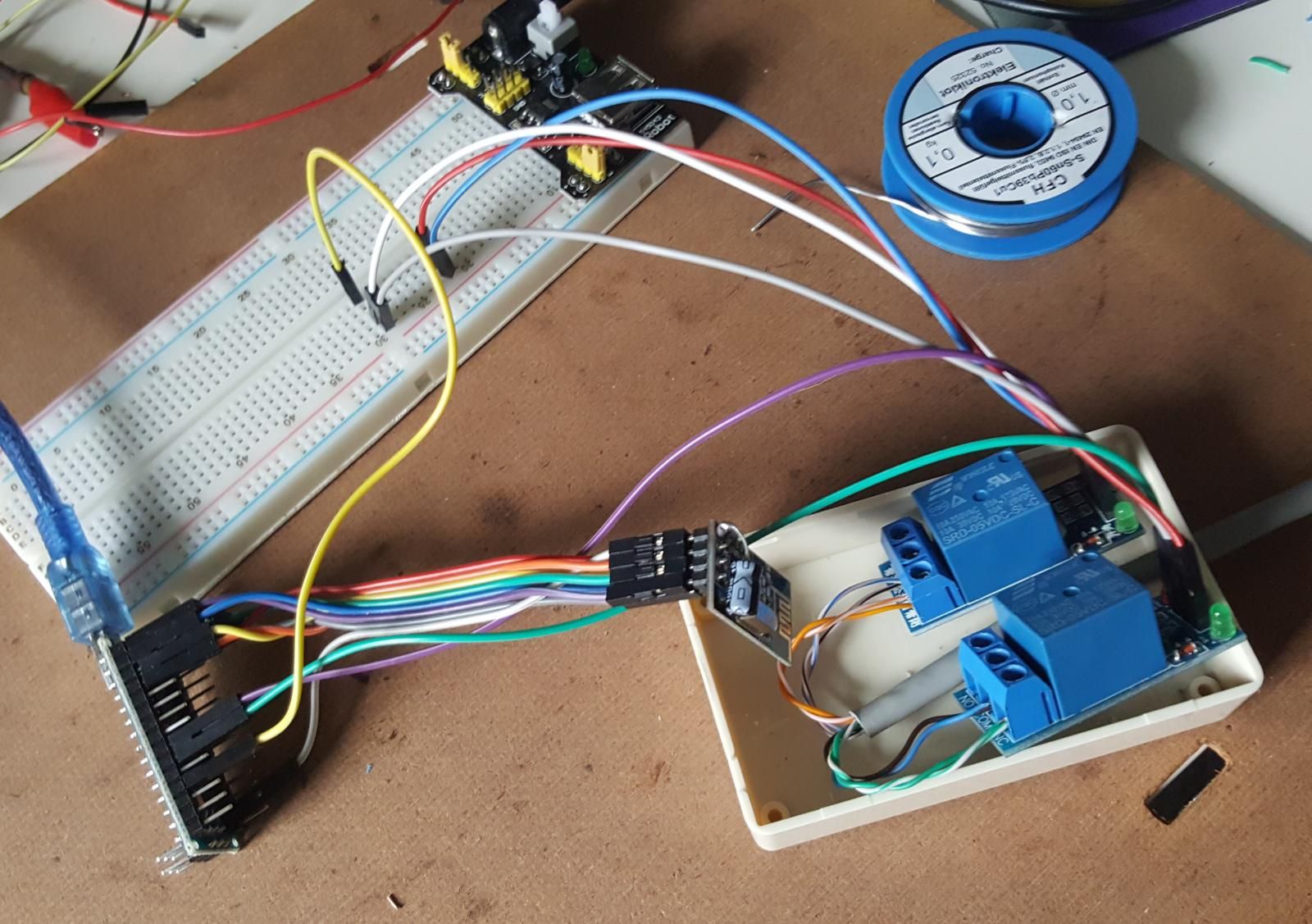
0_1500406156812_sketch_jul16a_-_Brinks_WTW.inoYou will need 2 Relais if you want to switch Switch_2 and Switch_3.
Please see attached the prototype... available for around €10 .

And then within Domoticz I can control it.
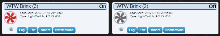
If the humidity in the bathroom is over 58% kick on the fan ;-)Oh btw. don't forget to connect the ground of the Relais to the Ground of the Arduino, otherwise it will not work.
Happy Mysensors day.
sincze.
-
I wanted to have my Renovent HR Large from Brink Climate Systems automated.
Unfortunately Brink offered a € 300 solution to do this wireless within the houseI thought.. Well it must be possible to use one of the Mysensors sketches to do so.
By default this system comes with a 3 way switch that is connected to an rj11 plug on the Renovent.
The RJ11 has 3 cables- Yellow
- Red
- Black
After figuring out how the 3 way switched worked it was an easy task with one of the example sketches.
- Yellow + Black = Switch_2
- Red + Black = Switch_3
- By default nothing is connected = Switch_1.
If you would like to measure voltage you will measure aroun 13,88v on
- yellow-black
- red-black.
The sketch can be found here:
0_1500406156812_sketch_jul16a_-_Brinks_WTW.inoYou will need 2 Relais if you want to switch Switch_2 and Switch_3.
Please see attached the prototype... available for around €10 .
And then within Domoticz I can control it.
If the humidity in the bathroom is over 58% kick on the fan ;-)Oh btw. don't forget to connect the ground of the Relais to the Ground of the Arduino, otherwise it will not work.
Happy Mysensors day.
sincze.
@sincze https://github.com/sincze/mysensors_brinks_renovent (seems the link in the post did not work)
-
Just an update regarding the Renovent Climate system:
I created the following cheat sheet: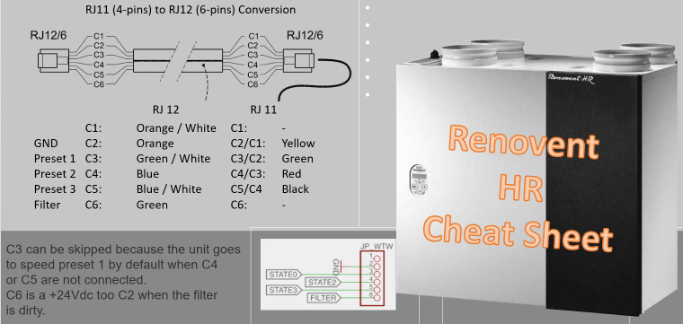
To be able to read the 'filter' value I converted the default RJ11 to RJ12.
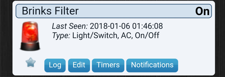
Now it should be able to warn me that I need to change the filter.
As I use the EasyPCB and already used all available pins on the prototype board, I had to solder an extra wire to pin 8.
Q: How do I access A2, A3 and D8? A: They are not accesses through the PCB, so you need to directly solder to the pro mini.As this Pin 8 is not used with pull up resistor (I thought it was dangerous to do that because adding 3v of the Renovent would kill the input.) I needed to build some sort of pull-down resistor from keeping the input pin from floating. And hell yes it was floating like hell (resulting in a lot of messages, that even the debouncer was unable to deal with).
Normally when the filter is 'clean' there is a 0v on P8. If the filter needs to be cleaned there is a +/- 3v on P8
This how it was solved:
-
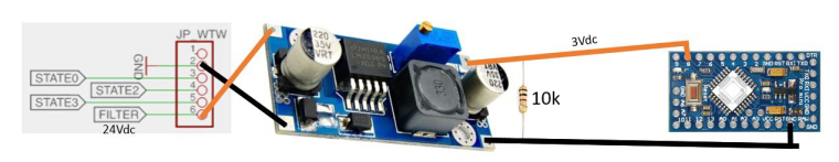
Thank you for the inspiration sincze! I have made my own iteration based on yours for a Brink renovent 300/400 excellent, ESP8266 and home assistant integration. I will post some snippets, mainly because the color coding was somewhat confusing as many wires have different colors than yours.
I used an RJ12 cable and splitter so that my Brink RF transmitter can stay in place and also copied your idea for the filter indicator.

The RJ12 pinout is as follows (see p. 28 in the installation guide)
Pin 1: 24V (not connected but could theoretically be used as a power supply)
Pin 2: GND
Pin 3: Position 0/sleep mode (not connected in my case
Pin 4: position 2, to enable connect to ground with relay (~13 V to ground)
Pin 5: position 3, to enable connect to ground with relay (~13V to ground)
Pin 6: Filter indicator (gives off 24V to GND when filter needs cleaning/replacement).Note that:
- the Brink defaults to position 1 and that it is capable of handling two inputs simultaneously as it is made to handle multiple switches (e.g. 2 RF modules). Nevertheless I 'interlocked' both relays in ESPhome.
- I'm not yet sure what's current is drawn if the filter indicator is on. Might need a heat sink for the voltage regulator.
- I connected a 5V microUSB power supply to my ESP8266 in order to supply the necessary 5V to the relays.
My wiring:
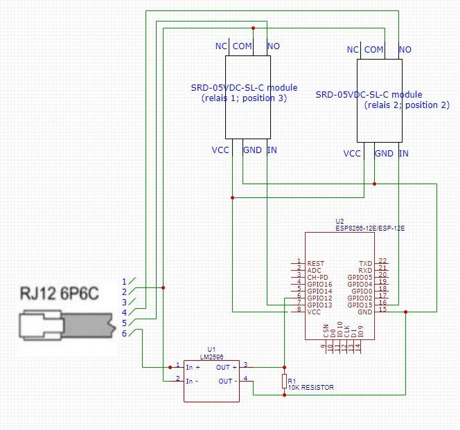
In ESPhome I configured it as follows:
switch:
  - platform: gpio
    name: "position 3"
    id: relay1
    pin: D7
    interlock: [relay2]
  - platform: gpio
    name: "position 2"
    id: relay2
    pin: D8
    interlock: [relay1]
  - platform: template
    name: "position1"
    id: "position1"
    turn_on_action:
     - switch.turn_off: relay1
     - switch.turn_off: relay2
     - switch.turn_off: position1

binary_sensor:
  - platform: gpio
    device_class: problem
    pin: D6
    name: "Brink renovent filter indicator"
In home assistant I used this this blueprint to automatically switch the fan to position3 based on the bathroom humidity.
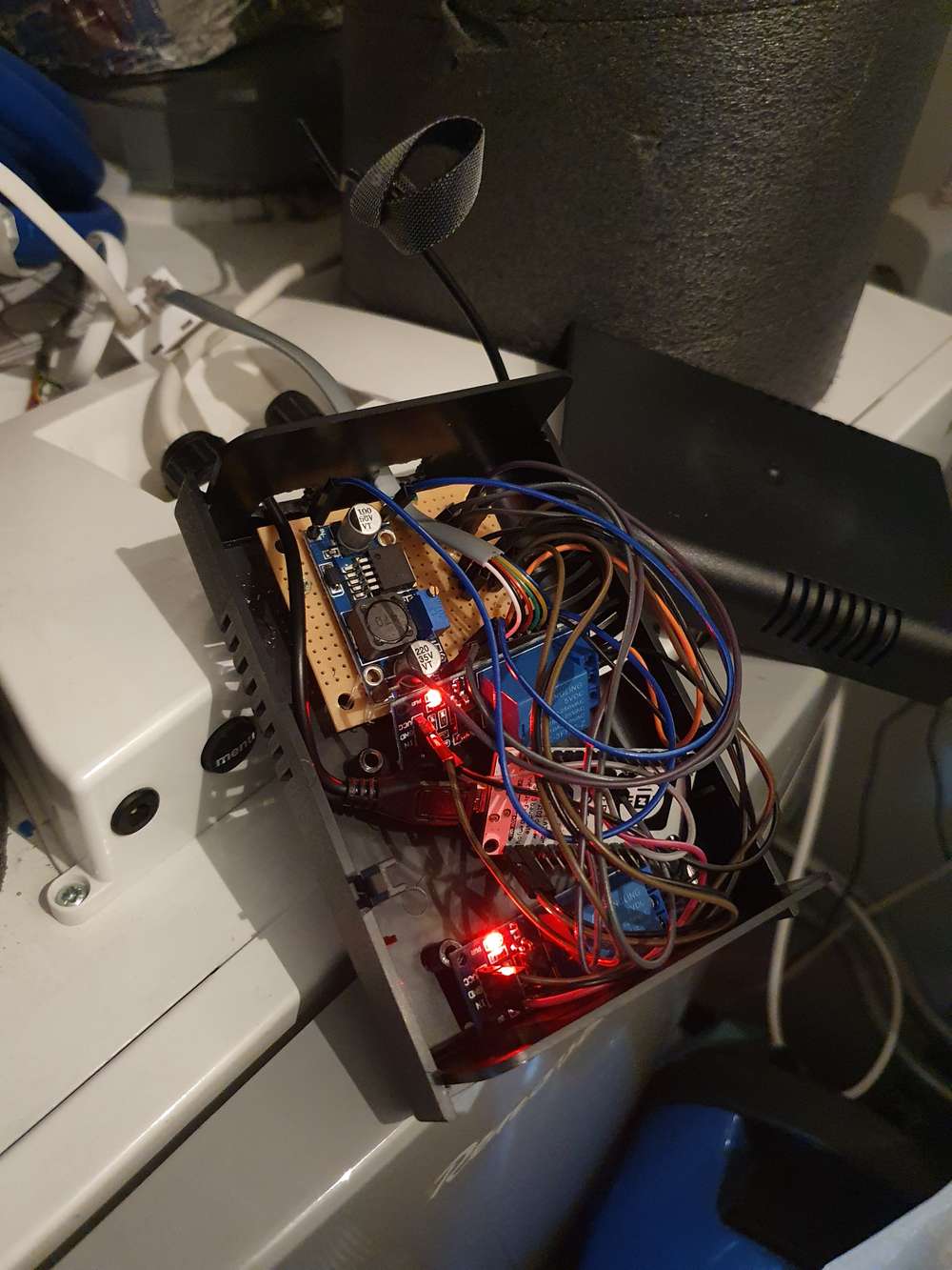
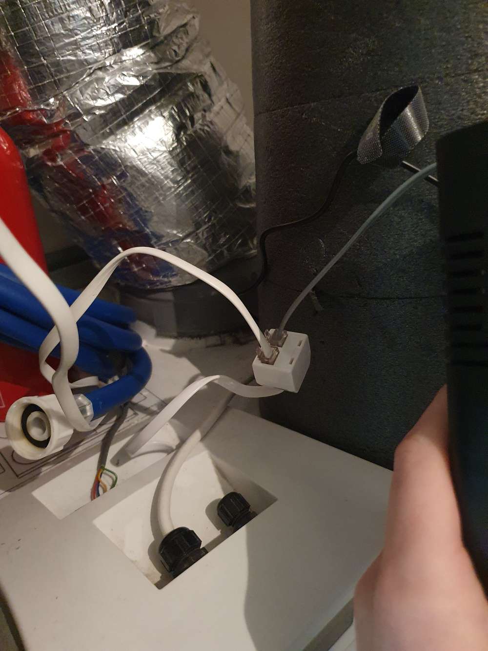
Some (messy) pictures are included of the device and HA lovelace view.
-
Hello,
I you are interested in the full integration with Brink Renovent HR, please have a look here:https://github.com/raf1000/brink_openhab/blob/main/README.md
The integration is with openhab but similar one can be done with home assistant I suppose (mqtt)
It is tested with Brink Renovent HR, but Brink Renovent Excellent has the opentherm protocol available as well...
Hello! It looks like you're interested in this conversation, but you don't have an account yet.
Getting fed up of having to scroll through the same posts each visit? When you register for an account, you'll always come back to exactly where you were before, and choose to be notified of new replies (either via email, or push notification). You'll also be able to save bookmarks and upvote posts to show your appreciation to other community members.
With your input, this post could be even better 💗
Register Login