Back to Basics - Arduino MEGA + NRF24+LNA + W5100 Shield
-
Hi Folks,
After my last little brain implosion, I've decided to go back to basics.
I've completely rebuilt my gatewayNode from the ground up, and included the current sketch below.
When I run the serial monitor on the bench, i get a slow "eth failed" message, which I expect (sadly I don't have Ethernet connection at my outdoor workspace) and when I plug it into the router (both USB to power the unit and eth) I get an "eth failed" message approx 4 times a second, but I can PING the address.
I can't add the gateway to MyController, it just times out.
I am powering the radio directly from the 3v pin on the mega, (no cap as I don't have any here) and there is nothing other than the LED indicators plugged into it.
I'm just trying to work out where I should START looking, before i go back to pulling my hair out!
Any advice greatly appreciated!
/**
 * NRF24/Ethernet Gateway Node - v0.1
 */

// Enable debug prints to serial monitor
#define MY_DEBUG

// Pin Confuguration for Arduino Mega
#define MY_RF24_CE_PIN 49
#define MY_RF24_CS_PIN 53

// Radio type
#define MY_RADIO_NRF24

// Ethernet module type
#define MY_GATEWAY_W5100

// MAC Address
#define MY_MAC_ADDRESS 0xDE, 0xAD, 0xBE, 0xEF, 0xFE, 0xED

// Enable MY_IP_ADDRESS here if you want a static ip address (no DHCP)
#define MY_IP_ADDRESS 10,0,0,201
#define MY_IP_GATEWAY_ADDRESS 10,0,0,1
#define MY_IP_SUBNET_ADDRESS 255,255,255,0

// Listening Port
#define MY_PORT 5003

// MyController IP Address
#define MY_CONTROLLER_IP_ADDRESS 10,0,0,200

// Enable inclusion mode
#define MY_INCLUSION_MODE_FEATURE
// Enable Inclusion mode button on gateway
//#define MY_INCLUSION_BUTTON_FEATURE
// Set inclusion mode duration (in seconds)
#define MY_INCLUSION_MODE_DURATION 60
// Digital pin used for inclusion mode button
//#define MY_INCLUSION_MODE_BUTTON_PIN  3

// Set blinking period
#define MY_DEFAULT_LED_BLINK_PERIOD 300

// Flash leds on rx/tx/err
#define MY_DEFAULT_ERR_LED_PIN 22  // Error led pin
#define MY_DEFAULT_RX_LED_PIN  26  // Receive led pin
#define MY_DEFAULT_TX_LED_PIN  24  // Transmit led pin

#include <Ethernet.h>
#include <MySensors.h>

void setup()
{
	// Setup locally attached sensors
}

void presentation()
{
	// Present locally attached sensors here
}

void loop()
{
	// Send locally attached sensors data here
}
-
@zachflem do you have more than one W5100 running at home? All W5100 need to have a unique mac address.
Could ypu post the full debug log?
-
Evening @mfalkvidd
do you have more than one W5100 running at home? All W5100 need to have a unique mac address.
This is the only one currently. I'm aware of the need for unique MAC addresses and have a schema in place to cover this.
Could ypu post the full debug log?
Sure! This is the first 3 bursts that appear, anything after this just increases the TSM:FAIL:CNT=X count
I'm not even getting the ETH:FAIL errors now =(
0 MCO:BGN:INIT GW,CP=RNNGA---,VER=2.2.0
3 TSM:INIT
4 TSF:WUR:MS=0
11 !TSM:INIT:TSP FAIL
13 TSM:FAIL:CNT=1
14 TSM:FAIL:DIS
16 TSF:TDI:TSL
10018 TSM:FAIL:RE-INIT
10020 TSM:INIT
10028 !TSM:INIT:TSP FAIL
10030 TSM:FAIL:CNT=2
10032 TSM:FAIL:DIS
10034 TSF:TDI:TSL
20036 TSM:FAIL:RE-INIT
20038 TSM:INIT
20045 !TSM:INIT:TSP FAIL
20047 TSM:FAIL:CNT=3
20049 TSM:FAIL:DIS
20051 TSF:TDI:TSL
-
TSM:INIT:TSP FAILmeans the nrf24 could not be initialized. The most common cause is miswiring or "wrong" pins defined.
The defines in your sketch look good to me.
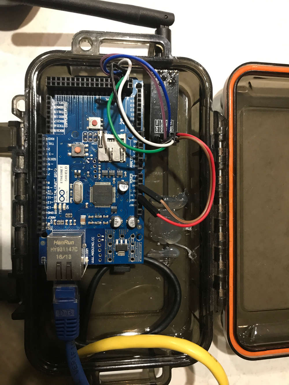
Could you post a photo of your wiring? Sometimes it helps to get a new pair of eyes on it. Try to take a photo (or multiple) so each wire can be traced from start to finish.
-
I've got the following:
3v-----------RED------------V+
GND-------BROWN------GND
49----------WHITE--------CE
50----------PURPLE------MISO
51----------BLUE-----------MOSI
52----------GREEN--------SCK
53----------BLACK--------CSN
-
@zachflem I can't tell from the picture where the blue, white and purple wires are connected to the mega, but except that it looks good. Nice case.
-
@mfalkvidd the blue, white and purple are 100% as per my wiring description. Might it have something to do with not having the cap on the power?
I'm at a loss as to what is going wrong here...
The case is a AUD$10 waterproof unit (before i drilled holes in the side of it) from Bunnings: https://goo.gl/kzDaZi
I've also got a bigger (AUD$16) version housing a bigger project: https://goo.gl/zgvd7h
-
@zachflem using the nrf without cap often (almost always) leads to failed transmission, but it should not affect initialization of the radio.