How To: Make a Simple/Cheap Scene Controller (with video)
-
Hi Everyone,
I recently decided to make a very simple/cheap scene controller with a 1x4 membrane keypad. I normally try to automate as many things as I can but sometimes it's just nice to have some physical buttons. I have this in my bedroom so I can turn on/off lights, fans etc without having to open my eyes. Hopefully this will be of use to someone...
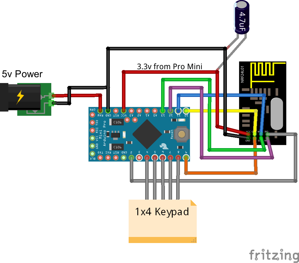
/**
 * The MySensors Arduino library handles the wireless radio link and protocol
 * between your home built sensors/actuators and HA controller of choice.
 * The sensors forms a self healing radio network with optional repeaters. Each
 * repeater and gateway builds a routing tables in EEPROM which keeps track of the
 * network topology allowing messages to be routed to nodes.
 *
 * Created by Henrik Ekblad <henrik.ekblad@mysensors.org>
 * Copyright (C) 2013-2015 Sensnology AB
 * Full contributor list: https://github.com/mysensors/Arduino/graphs/contributors
 *
 * Documentation: http://www.mysensors.org
 * Support Forum: http://forum.mysensors.org
 *
 * This program is free software; you can redistribute it and/or
 * modify it under the terms of the GNU General Public License
 * version 2 as published by the Free Software Foundation.
 *
 *******************************
 *
 * REVISION HISTORY
 * Version 1.0 - PeteWill
 *
 * DESCRIPTION
 * A simple scene controller for use with MySensors.  8 scenes can be executed.
 * 4 with short button presses and 4 with long button presses (held .5 seconds or more).
 * Watch a how to video here: https://youtu.be/KMGj5Bi7vL0
 */

#include <Keypad.h>
#include <SPI.h>
#include <MySensor.h>

#define NODE_ID 14 // or set to AUTO if you want gw to assign a NODE_ID for you.
#define SN "Scene Controller"
#define SV "1.0"


#define KEYPAD_CHILD_ID 0

MySensor gw;
MyMessage scene(KEYPAD_CHILD_ID, V_SCENE_ON);

const byte ROWS = 4; //four rows
const byte COLS = 1; //three columns
char keys[ROWS][COLS] = {
  {'1'},
  {'2'},
  {'3'},
  {'4'}
};

byte rowPins[ROWS] = {6, 7, 4, 5}; //connect to the row pinouts of the keypad
byte colPins[COLS] = {8}; //connect to the column pinouts of the keypad

Keypad keypad = Keypad( makeKeymap(keys), rowPins, colPins, ROWS, COLS );
byte lastState;


void setup() {
  gw.begin(NULL, NODE_ID);
  gw.sendSketchInfo(SN, SV);
  gw.present(KEYPAD_CHILD_ID, S_SCENE_CONTROLLER);
  keypad.addEventListener(keypadEvent); // Add an event listener for this keypad
}

void loop() {
  char key = keypad.getKey();
}

void keypadEvent(KeypadEvent key) {
  switch (keypad.getState()) {

    case PRESSED:
      lastState = 1;
      break;

    case HOLD:
      lastState = 2;
      break;

    case RELEASED:
      int keyInt = key - '0'; //Quick way to convert Char to Int so it can be sent to controller
      if (lastState == 2) {
        keyInt = keyInt + 4; //If button is held, add 4.  If using more than 4 buttons this number will need to be changed
      }
      gw.send(scene.set(keyInt));
      break;
  }
}
Here is a link for a keypad: http://www.ebay.com/itm/171505110526?_trksid=p2057872.m2749.l2649&ssPageName=STRK%3AMEBIDX%3AIT
Here is another option for a scene controller keypad contributed by @AWI. It has capacitive touch buttons and an interrupt to battery power can be used. Thanks @AWI!
http://forum.mysensors.org/topic/2001/how-to-make-a-simple-cheap-scene-controller-with-video/14 -
Great & simple.. for a "touch" version (similar code/connection, price is for 10 pcs. ;-) )
-
-
-
@petewill To get you started with capacitive: the ones with the TTPxxx chip in 4/8/16 button versions like have pins with leds for every button. Can also generate an interrupt at keypress (so no need to poll the keyboard in low-power applications). And can can also be used with a simple serial protocol (only 2/3 pins needed). I would be happy to supply the code (but don't want to mess-up your great topic any further ;-) )
-
@DrJeff Yes, that would be great! Someday...
@msebbe Yes, this version would have short battery life because it's not sleeping. But, if @AWI posts his code a battery version sounds possible.
@Hoffan you can get them here: http://www.ebay.com/itm/171505110526?_trksid=p2057872.m2749.l2649&ssPageName=STRK%3AMEBIDX%3AIT
@AWI That would be great if you could supply the code for a capacitive sleeping node! If you could supply the wiring diagram and parts list also I will add it to the first post as another option (giving credit to you of course). Thanks!
-
-
@Tomasz-Pazio The keyboard you mention is a standard 4 x 4 matrix keyboard. You can wire it with 8 pins for which you can also use the analog pins. These can be addressed by A0, A1, etc. The library @petewill used in the sketch can handle this keyboard.
-
-
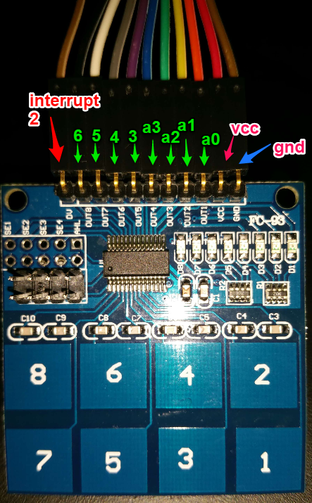
Not even close to @petewill 's great build descriptions but here my version the "touch" version which can be battery operated. The used keyboard uses around 150uA. The touch panel generates an interrupt which wakes the arduino, reads the key and swiches a scene.
The code below toggles between 'Scene ON' and 'Scene OFF' and stores the last state in EEPROM.
All credits to @petewill
/** * The MySensors Arduino library handles the wireless radio link and protocol * between your home built sensors/actuators and HA controller of choice. * The sensors forms a self healing radio network with optional repeaters. Each * repeater and gateway builds a routing tables in EEPROM which keeps track of the * network topology allowing messages to be routed to nodes. * * Created by Henrik Ekblad <henrik.ekblad@mysensors.org> * Copyright (C) 2013-2015 Sensnology AB * Full contributor list: https://github.com/mysensors/Arduino/graphs/contributors * * Documentation: http://www.mysensors.org * Support Forum: http://forum.mysensors.org * * This program is free software; you can redistribute it and/or * modify it under the terms of the GNU General Public License * version 2 as published by the Free Software Foundation. * ******************************* * * REVISION HISTORY * Version 1.0 - PeteWill * 1.1 - AWI * * DESCRIPTION * A simple scene controller for use with MySensors. 8 scenes can be executed * with an 8 key keypad, make sure to attach the pins and fill keyPins[] resp. * Watch a how to video here: https://youtu.be/KMGj5Bi7vL0 */ #include <SPI.h> #include <MySensor.h> #define SN "Scene Controller" #define SV "1.0" #define NODE_ID 14 // or set to AUTO if you want gw to assign a NODE_ID for you. const byte KEYPAD_CHILD_ID = 0 ; MySensor gw; MyMessage scene_on(KEYPAD_CHILD_ID, V_SCENE_ON); MyMessage scene_off(KEYPAD_CHILD_ID, V_SCENE_OFF); const int DV = 2; //DataValid (=key pressed) pin goes there const int DV_int = DV-2; //DataValid interrupt on pin 3 => 1 const unsigned long SLEEP_TIME = 3600000 ; // sleep for an hour (or more if you want to) volatile boolean DVint = false ; // interrupt flag, set by interrupt const byte keyPins[] = {A0, A1, A2, A3, 3, 4, 5, 6};// keypad pins, (8 pin keyboard) byte keyState[8] ; // hold current keystate (copy of EEPROM) void setup(){ gw.begin(NULL, NODE_ID); gw.sendSketchInfo(SN, SV); gw.present(KEYPAD_CHILD_ID, S_SCENE_CONTROLLER); pinMode(DV,INPUT); // Data Valid (interrupt) for (int i=0 ; i < sizeof(keyPins); i++){ keyState[i] = gw.loadState(i) ; // load last Scenestates from EEPROM } } // loop only if interrupt, else sleep void loop(){ // if so get a key value and send to MySensosrs network byte key = fetchData(); // if so fetch key Serial.println(key); // serial print as binary if (key > 0){ // (key-1) is used as index boolean keyVal = !gw.loadState(key-1); // use lastState from EEPROM and toggle gw.saveState(key-1, keyVal); // save new state to EEPROM if (keyVal) gw.send(scene_on.set(key-1)); // set the Scene On or Off else gw.send(scene_off.set(key-1)); } DVint=false; // reset interrupt flag gw.sleep(DV_int, RISING, SLEEP_TIME); // node wakes up on key interrupt or time Serial.println(" key pressed or time trigger "); } // interrupt routine, only sets flag void intrp(){DVint = true;}; // fetch serial data, only highest number key is returned byte fetchData(){ int Key=0; // default key = 0 (nothing pressed) for (byte i = 0 ; i < sizeof(keyPins) ; i++){ // check each key, if(digitalRead(keyPins[i]) == HIGH) Key=i+1;// set key if pressed (now only highest key) } return Key; // return Key (0 if no key pressed) } -
ok easy.... two changes and 32 scenes can be managed :)
const byte ROWS = 4; const byte COLS = 4; byte rowPins[ROWS] = {3, 4, 5, 6}; byte colPins[COLS] = {A0, A1, A2, A3}; char keys[ROWS][COLS] = {{'1','2','3','A'}, {'4','5','6','B'}, {'7','8','9','C'}, {'*','0','#','D'}}; ----------------------------------------- keyInt = keyInt + 100; -
Not even close to @petewill 's great build descriptions but here my version the "touch" version which can be battery operated. The used keyboard uses around 150uA. The touch panel generates an interrupt which wakes the arduino, reads the key and swiches a scene.
The code below toggles between 'Scene ON' and 'Scene OFF' and stores the last state in EEPROM.
All credits to @petewill
/** * The MySensors Arduino library handles the wireless radio link and protocol * between your home built sensors/actuators and HA controller of choice. * The sensors forms a self healing radio network with optional repeaters. Each * repeater and gateway builds a routing tables in EEPROM which keeps track of the * network topology allowing messages to be routed to nodes. * * Created by Henrik Ekblad <henrik.ekblad@mysensors.org> * Copyright (C) 2013-2015 Sensnology AB * Full contributor list: https://github.com/mysensors/Arduino/graphs/contributors * * Documentation: http://www.mysensors.org * Support Forum: http://forum.mysensors.org * * This program is free software; you can redistribute it and/or * modify it under the terms of the GNU General Public License * version 2 as published by the Free Software Foundation. * ******************************* * * REVISION HISTORY * Version 1.0 - PeteWill * 1.1 - AWI * * DESCRIPTION * A simple scene controller for use with MySensors. 8 scenes can be executed * with an 8 key keypad, make sure to attach the pins and fill keyPins[] resp. * Watch a how to video here: https://youtu.be/KMGj5Bi7vL0 */ #include <SPI.h> #include <MySensor.h> #define SN "Scene Controller" #define SV "1.0" #define NODE_ID 14 // or set to AUTO if you want gw to assign a NODE_ID for you. const byte KEYPAD_CHILD_ID = 0 ; MySensor gw; MyMessage scene_on(KEYPAD_CHILD_ID, V_SCENE_ON); MyMessage scene_off(KEYPAD_CHILD_ID, V_SCENE_OFF); const int DV = 2; //DataValid (=key pressed) pin goes there const int DV_int = DV-2; //DataValid interrupt on pin 3 => 1 const unsigned long SLEEP_TIME = 3600000 ; // sleep for an hour (or more if you want to) volatile boolean DVint = false ; // interrupt flag, set by interrupt const byte keyPins[] = {A0, A1, A2, A3, 3, 4, 5, 6};// keypad pins, (8 pin keyboard) byte keyState[8] ; // hold current keystate (copy of EEPROM) void setup(){ gw.begin(NULL, NODE_ID); gw.sendSketchInfo(SN, SV); gw.present(KEYPAD_CHILD_ID, S_SCENE_CONTROLLER); pinMode(DV,INPUT); // Data Valid (interrupt) for (int i=0 ; i < sizeof(keyPins); i++){ keyState[i] = gw.loadState(i) ; // load last Scenestates from EEPROM } } // loop only if interrupt, else sleep void loop(){ // if so get a key value and send to MySensosrs network byte key = fetchData(); // if so fetch key Serial.println(key); // serial print as binary if (key > 0){ // (key-1) is used as index boolean keyVal = !gw.loadState(key-1); // use lastState from EEPROM and toggle gw.saveState(key-1, keyVal); // save new state to EEPROM if (keyVal) gw.send(scene_on.set(key-1)); // set the Scene On or Off else gw.send(scene_off.set(key-1)); } DVint=false; // reset interrupt flag gw.sleep(DV_int, RISING, SLEEP_TIME); // node wakes up on key interrupt or time Serial.println(" key pressed or time trigger "); } // interrupt routine, only sets flag void intrp(){DVint = true;}; // fetch serial data, only highest number key is returned byte fetchData(){ int Key=0; // default key = 0 (nothing pressed) for (byte i = 0 ; i < sizeof(keyPins) ; i++){ // check each key, if(digitalRead(keyPins[i]) == HIGH) Key=i+1;// set key if pressed (now only highest key) } return Key; // return Key (0 if no key pressed) } -
Hi Petewill
I 'd like to build your Scene Controller but I am missing the keypad.h library. Where can I get it?greetings
Brom_Snor@brom_snor
Sorry about that. I thought it was part of the default libraries. I must have downloaded it a while ago. This one should work: http://playground.arduino.cc/Code/Keypad -
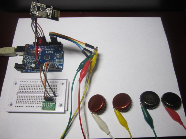
Hi all - Another capacitive version with an "out of the bottle" keypad - 4 buttons. Like AWI's version, also toggles between 'Scene ON' and 'Scene OFF', but states are kept in a variable (keyState) - LEDs added for better toogle visibility. Capacitive routine found at http://www.arduino.cc/playground/Code/CapacitiveSensor
Great post from @petewill and nice version from AWI. Thanks!
#include <SPI.h>
#include <MySensor.h>
#define SN "Scene Controller"
#define SV "1.2"
#define NODE_ID 20 // or set to AUTO if you want gw to assign a NODE_ID for you.
const byte KEYPAD_CHILD_ID = 1 ;
MySensor gw;
MyMessage scene_on(KEYPAD_CHILD_ID, V_SCENE_ON);
MyMessage scene_off(KEYPAD_CHILD_ID, V_SCENE_OFF);long time = 0;
long debounce = 800;
const byte keyLeds[] = {14, 15, 16, 17}; //LEDs to turn on/off
const byte keyPins[] = {2, 3, 4, 5}; //capacitive keys
byte keyState = B1111; //save LEDs statesvoid setup() {
Serial.begin(9600);
for (byte i = 0 ; i < sizeof(keyLeds) ; i++)
{ pinMode(keyLeds[i], OUTPUT);
}
gw.begin(NULL, NODE_ID);
gw.sendSketchInfo(SN, SV);
gw.present(KEYPAD_CHILD_ID, S_SCENE_CONTROLLER);
}void loop() {
uint8_t pinRead;
for (byte i = 0 ; i < sizeof(keyPins) ; i++){
pinRead = readCapacitivePin(keyPins[i]);
if (pinRead > 2 && millis() - time > debounce) {
digitalWrite(keyLeds[i], bitRead(keyState,i));
if (bitRead(keyState,i) == 1){
gw.send(scene_on.set(keyPins[i]));
bitWrite(keyState, i, 0);} else
{gw.send(scene_off.set(keyPins[i]));
bitWrite(keyState, i, 1);}
time = millis();
}
}
}// — readCapPin found at http://www.arduino.cc/playground/Code/CapacitiveSensor
uint8_t readCapacitivePin(int pinToMeasure) {// Variables used to translate from Arduino to AVR pin naming
volatile uint8_t* port;
volatile uint8_t* ddr;
volatile uint8_t* pin;
// Here we translate the input pin number from
// Arduino pin number to the AVR PORT, PIN, DDR,
// and which bit of those registers we care about.
byte bitmask;
port = portOutputRegister(digitalPinToPort(pinToMeasure));
ddr = portModeRegister(digitalPinToPort(pinToMeasure));
bitmask = digitalPinToBitMask(pinToMeasure);
pin = portInputRegister(digitalPinToPort(pinToMeasure));
// Discharge the pin first by setting it low and output
*port &= ~(bitmask);
*ddr |= bitmask;
delay(1);
// Make the pin an input with the internal pull-up on
*ddr &= ~(bitmask);
*port |= bitmask;// Now see how long the pin to get pulled up. This manual unrolling of the loop
// decreases the number of hardware cycles between each read of the pin,
// thus increasing sensitivity.
uint8_t cycles = 17;
if (*pin & bitmask) { cycles = 0;}
else if (*pin & bitmask) { cycles = 1;}
else if (*pin & bitmask) { cycles = 2;}
else if (*pin & bitmask) { cycles = 3;}
else if (*pin & bitmask) { cycles = 4;}
else if (*pin & bitmask) { cycles = 5;}
else if (*pin & bitmask) { cycles = 6;}
else if (*pin & bitmask) { cycles = 7;}
else if (*pin & bitmask) { cycles = 8;}
else if (*pin & bitmask) { cycles = 9;}
else if (*pin & bitmask) { cycles = 10;}
else if (*pin & bitmask) { cycles = 11;}
else if (*pin & bitmask) { cycles = 12;}
else if (*pin & bitmask) { cycles = 13;}
else if (*pin & bitmask) { cycles = 14;}
else if (*pin & bitmask) { cycles = 15;}
else if (*pin & bitmask) { cycles = 16;}// Discharge the pin again by setting it low and output
// It’s important to leave the pins low if you want to
// be able to touch more than 1 sensor at a time – if
// the sensor is left pulled high, when you touch
// two sensors, your body will transfer the charge between
// sensors.
*port &= ~(bitmask);
*ddr |= bitmask;return cycles;
} -
Hi all - Another capacitive version with an "out of the bottle" keypad - 4 buttons. Like AWI's version, also toggles between 'Scene ON' and 'Scene OFF', but states are kept in a variable (keyState) - LEDs added for better toogle visibility. Capacitive routine found at http://www.arduino.cc/playground/Code/CapacitiveSensor
Great post from @petewill and nice version from AWI. Thanks!
#include <SPI.h>
#include <MySensor.h>
#define SN "Scene Controller"
#define SV "1.2"
#define NODE_ID 20 // or set to AUTO if you want gw to assign a NODE_ID for you.
const byte KEYPAD_CHILD_ID = 1 ;
MySensor gw;
MyMessage scene_on(KEYPAD_CHILD_ID, V_SCENE_ON);
MyMessage scene_off(KEYPAD_CHILD_ID, V_SCENE_OFF);long time = 0;
long debounce = 800;
const byte keyLeds[] = {14, 15, 16, 17}; //LEDs to turn on/off
const byte keyPins[] = {2, 3, 4, 5}; //capacitive keys
byte keyState = B1111; //save LEDs statesvoid setup() {
Serial.begin(9600);
for (byte i = 0 ; i < sizeof(keyLeds) ; i++)
{ pinMode(keyLeds[i], OUTPUT);
}
gw.begin(NULL, NODE_ID);
gw.sendSketchInfo(SN, SV);
gw.present(KEYPAD_CHILD_ID, S_SCENE_CONTROLLER);
}void loop() {
uint8_t pinRead;
for (byte i = 0 ; i < sizeof(keyPins) ; i++){
pinRead = readCapacitivePin(keyPins[i]);
if (pinRead > 2 && millis() - time > debounce) {
digitalWrite(keyLeds[i], bitRead(keyState,i));
if (bitRead(keyState,i) == 1){
gw.send(scene_on.set(keyPins[i]));
bitWrite(keyState, i, 0);} else
{gw.send(scene_off.set(keyPins[i]));
bitWrite(keyState, i, 1);}
time = millis();
}
}
}// — readCapPin found at http://www.arduino.cc/playground/Code/CapacitiveSensor
uint8_t readCapacitivePin(int pinToMeasure) {// Variables used to translate from Arduino to AVR pin naming
volatile uint8_t* port;
volatile uint8_t* ddr;
volatile uint8_t* pin;
// Here we translate the input pin number from
// Arduino pin number to the AVR PORT, PIN, DDR,
// and which bit of those registers we care about.
byte bitmask;
port = portOutputRegister(digitalPinToPort(pinToMeasure));
ddr = portModeRegister(digitalPinToPort(pinToMeasure));
bitmask = digitalPinToBitMask(pinToMeasure);
pin = portInputRegister(digitalPinToPort(pinToMeasure));
// Discharge the pin first by setting it low and output
*port &= ~(bitmask);
*ddr |= bitmask;
delay(1);
// Make the pin an input with the internal pull-up on
*ddr &= ~(bitmask);
*port |= bitmask;// Now see how long the pin to get pulled up. This manual unrolling of the loop
// decreases the number of hardware cycles between each read of the pin,
// thus increasing sensitivity.
uint8_t cycles = 17;
if (*pin & bitmask) { cycles = 0;}
else if (*pin & bitmask) { cycles = 1;}
else if (*pin & bitmask) { cycles = 2;}
else if (*pin & bitmask) { cycles = 3;}
else if (*pin & bitmask) { cycles = 4;}
else if (*pin & bitmask) { cycles = 5;}
else if (*pin & bitmask) { cycles = 6;}
else if (*pin & bitmask) { cycles = 7;}
else if (*pin & bitmask) { cycles = 8;}
else if (*pin & bitmask) { cycles = 9;}
else if (*pin & bitmask) { cycles = 10;}
else if (*pin & bitmask) { cycles = 11;}
else if (*pin & bitmask) { cycles = 12;}
else if (*pin & bitmask) { cycles = 13;}
else if (*pin & bitmask) { cycles = 14;}
else if (*pin & bitmask) { cycles = 15;}
else if (*pin & bitmask) { cycles = 16;}// Discharge the pin again by setting it low and output
// It’s important to leave the pins low if you want to
// be able to touch more than 1 sensor at a time – if
// the sensor is left pulled high, when you touch
// two sensors, your body will transfer the charge between
// sensors.
*port &= ~(bitmask);
*ddr |= bitmask;return cycles;
}
Hello! It looks like you're interested in this conversation, but you don't have an account yet.
Getting fed up of having to scroll through the same posts each visit? When you register for an account, you'll always come back to exactly where you were before, and choose to be notified of new replies (either via email, or push notification). You'll also be able to save bookmarks and upvote posts to show your appreciation to other community members.
With your input, this post could be even better 💗
Register Login