Easy/Newbie PCB for MySensors
-
Dallas temp sensors needs 3.3v VCC if I remember right. Not 5v.
@sundberg84 haha yes i was wondering that myself so tried it connecting it to 3,3v as well. However on the 5v nano working just fine. Technical specs tell me: Power supply range is 3.0V to 5.5V
also mysensors link
Pretty strange huh. -
@sundberg84 haha yes i was wondering that myself so tried it connecting it to 3,3v as well. However on the 5v nano working just fine. Technical specs tell me: Power supply range is 3.0V to 5.5V
also mysensors link
Pretty strange huh.@sincze my mistake. Really strange this... Should work just fine. Can you upload a better resolution picture of your hardware and the sketch you are using?
-
@sundberg84 haha yes i was wondering that myself so tried it connecting it to 3,3v as well. However on the 5v nano working just fine. Technical specs tell me: Power supply range is 3.0V to 5.5V
also mysensors link
Pretty strange huh.@sincze I have 10 of these DS18B20s strung over approximately 12m monitoring all rooms on both floors of my house and two side lofts, all running on 3.22v from a Pro-Mini. Never have skipped a beat, reporting every 5 minutes, well, aside from a telephone socket which pins went walkabout (the chips are crimped to RJ11s).
There is something not right with the physical arrangement if you can get the same circuit to report at 5v... -
@sincze my mistake. Really strange this... Should work just fine. Can you upload a better resolution picture of your hardware and the sketch you are using?
@sundberg84 I just soldered a myself a new out of the box pro mini using the same sketch..
10246 TSF:MSG:SEND,8-8-25-0,s=0,c=1,t=0,pt=7,l=5,sg=0,ft=4,st=OK:21.0
250560 TSF:MSG:SEND,8-8-25-0,s=0,c=1,t=0,pt=7,l=5,sg=0,ft=0,st=OK:21.1
255019 TSF:MSG:SEND,8-8-25-0,s=0,c=1,t=0,pt=7,l=5,sg=0,ft=0,st=OK:22.3
259476 TSF:MSG:SEND,8-8-25-0,s=0,c=1,t=0,pt=7,l=5,sg=0,ft=0,st=OK:23.8
263934 TSF:MSG:SEND,8-8-25-0,s=0,c=1,t=0,pt=7,l=5,sg=0,ft=0,st=OK:25.3
268393 TSF:MSG:SEND,8-8-25-0,s=0,c=1,t=0,pt=7,l=5,sg=0,ft=0,st=OK:26.5
272851 TSF:MSG:SEND,8-8-25-0,s=0,c=1,t=0,pt=7,l=5,sg=0,ft=0,st=OK:27.6
277310 TSF:MSG:SEND,8-8-25-0,s=0,c=1,t=0,pt=7,l=5,sg=0,ft=0,st=OK:28.1
281768 TSF:MSG:SEND,8-8-25-0,s=0,c=1,t=0,pt=7,l=5,sg=0,ft=0,st=OK:28.4
290677 TSF:MSG:SEND,8-8-25-0,s=0,c=1,t=0,pt=7,l=5,sg=0,ft=0,st=OK:28.3
295136 TSF:MSG:SEND,8-8-25-0,s=0,c=1,t=0,pt=7,l=5,sg=0,ft=0,st=OK:28.1
299594 TSF:MSG:SEND,8-8-25-0,s=0,c=1,t=0,pt=7,l=5,sg=0,ft=0,st=OK:27.8
304053 TSF:MSG:SEND,8-8-25-0,s=0,c=1,t=0,pt=7,l=5,sg=0,ft=0,st=OK:27.6
308511 TSF:MSG:SEND,8-8-25-0,s=0,c=1,t=0,pt=7,l=5,sg=0,ft=0,st=OK:27.3
312970 TSF:MSG:SEND,8-8-25-0,s=0,c=1,t=0,pt=7,l=5,sg=0,ft=0,st=OK:27.1
317428 TSF:MSG:SEND,8-8-25-0,s=0,c=1,t=0,pt=7,l=5,sg=0,ft=0,st=OK:26.8
321887 TSF:MSG:SEND,8-8-25-0,s=0,c=1,t=0,pt=7,l=5,sg=0,ft=0,st=OK:26.6
326345 TSF:MSG:SEND,8-8-25-0,s=0,c=1,t=0,pt=7,l=5,sg=0,ft=0,st=OK:26.4Victory... :)
-
@gohan Don't know. Pin3 could be used to drive the led tx without problems. It only did not work with the temp sensors. I moved the temp sensor to d2.... modified the sketch and it did not work as well. and d2 was driveing rx led. So well root cause unknown... solution: solder a new pro mini and keep the other one for different purpose.
@sincze Did you use D2+D3 on all the same devices?
-
@sincze Did you use D2+D3 on all the same devices?
@zboblamont @gohan The Sensor with the replaced Pro Mini is in production now ;-). I'll start soldering a new Easy/Newbie PCB, because once you know how to do it... it is Easy and test the individual pins with a door/window sensor.
-
Hi Sundberg84,
What could you advise for battery powering (remove led and regulator too) if I would like to use Mini 5V and measure the battery level too ?
thxBarna
@Barna the 5v pro mini are running a 16mhz crystal as default and this needs higher voltage to be stable compred to 8mhz (3.3v pro mini).
I have never tried this so can't give much advice but I would probably take the effort of reprogramming the fuses and bootloader to a internal 1mhz and run the hardware as that (the hardware is the same on 5v except the regulator and crystal )
-
Hi Sundberg84,
What could you advise for battery powering (remove led and regulator too) if I would like to use Mini 5V and measure the battery level too ?
thxBarna
-
Hi Sundberg84,
I have used this step up booster
https://www.ebay.com/itm/181612513907?rmvSB=truebut found this (2nd),
https://www.ebay.com/itm/10Pcs-Mini-2-in-1-1-8V-5V-to-3-3V-DC-Step-Down-Step-Up-Converter-Power-For-Ardu/182793323053?hash=item2a8f54c22d:g:PJMAAOSwYL9ZzAXC
It has lower noise, so I could connect the radio to the Mini. What do you think ? -
Hi Sundberg84,
I have used this step up booster
https://www.ebay.com/itm/181612513907?rmvSB=truebut found this (2nd),
https://www.ebay.com/itm/10Pcs-Mini-2-in-1-1-8V-5V-to-3-3V-DC-Step-Down-Step-Up-Converter-Power-For-Ardu/182793323053?hash=item2a8f54c22d:g:PJMAAOSwYL9ZzAXC
It has lower noise, so I could connect the radio to the Mini. What do you think ?@barna lower noice is better but I can not confirm this module is better. You have to try. Yes you can connect this to EasyPCB just like the first one.
-
Hi All!
Could someone suggest me an elegant way to extend the mysx connector? SO i would like to multiple the A4 A5 pins onto another prototype board to use more I2C devices....
@tommas just add a wire on the back side to the prototyping area ? You could design a MysX daughter board as well 😉
-
@tommas just add a wire on the back side to the prototyping area ? You could design a MysX daughter board as well 😉
Unofrtunately i havent got the skills and free time for a daughter board.:(. But doesnt have someone else a daughterboard?:)
-
@tommas just add a wire on the back side to the prototyping area ? You could design a MysX daughter board as well 😉
Or have you got any suggestion expansion board for arduino mini pro ? Something like this: arduino-pro-mini-undershield (but it can not buy on ebay)
-
Or have you got any suggestion expansion board for arduino mini pro ? Something like this: arduino-pro-mini-undershield (but it can not buy on ebay)
@tommas how about a wire to the prototyping area ?
-
Or have you got any suggestion expansion board for arduino mini pro ? Something like this: arduino-pro-mini-undershield (but it can not buy on ebay)
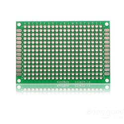
@tommas you could easily take a piece of prototyping PCB like this and create your own daughter/prototyping board if you need more space than the prototyping area has.

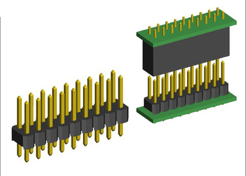
Use a set of connectors like this to connect to the MysX connector on the easy newbie board.

