💬 Easy/Newbie PCB for MySensors
-
@alexsh1 I know its a bit historical but could you post a pic or explain how you connect the lc-filter to the boost converter? Having issues here, 0.1uf cap didnt help...
Thanks....@Matt - It was some time ago now i experienced with this... but something like this:
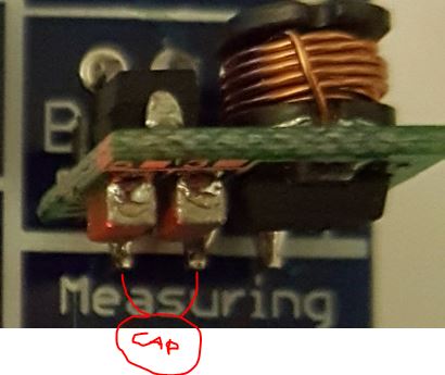 and to be hones maybe it was from ground (middle pin) to vin (left pin)... try both, cant do any harm. As I said - in most cases it works... I buy 10 and 10 batches and around 7-8 works good enough.
 -
@Matt - It was some time ago now i experienced with this... but something like this:
and to be hones maybe it was from ground (middle pin) to vin (left pin)... try both, cant do any harm. As I said - in most cases it works... I buy 10 and 10 batches and around 7-8 works good enough. -
@sundberg84 thanks, that is how I have soldered the 0.1uF cap but it hasnt improved things.
I was hoping @alexsh1 would be happy to chip in here and show me how to solder the 220uf cap and 3.3uH choke? -
@AWI hey thanks! I especially like this
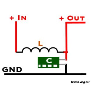
Although.... Something tells me L should be in series on Vout, sureley if it was between BAT and 3.3 voltage weird things would happen....
Might be time to finally try to figure out how to use that cheap old scope in my garage...
Also, as it happens, am just getting in to RC stuff (well for my son, but you know...) -
I have now updated this to Revision 9!
- Bigger mounting holes 2.5mm
- IRQ Jumper from Radio. This makes this trace disabled and D2 can be used for interupts unless jumper is connected.
- BAT and REG jumpers changed positions for better tracing.
- MysX 2,6
- Text on voltage regulater (Vout/Vin/Gnd)
- Bug with G on CAP now on the right side.
- GND and VCC swapped - so you could use a 2 pin block for GND/RAW as well.
- Capacitor to filter the booster output more (optional)
Please wait for PCB house to update to new gerber files before ordering (It should say M.Rev 5 (Manufacturer rev 5) for lastest revision when selecting PCB house)
I have not yet tested this rev... but no major changes so it should be pretty safe.
If you want to be 100% sure, download and order Rev 8.Controller: Proxmox VM - Home Assistant
MySensors GW: Arduino Uno - W5100 Ethernet, Gw Shield Nrf24l01+ 2,4Ghz
MySensors GW: Arduino Uno - Gw Shield RFM69, 433mhz
RFLink GW - Arduino Mega + RFLink Shield, 433mhz -
I have now updated this to Revision 9!
- Bigger mounting holes 2.5mm
- IRQ Jumper from Radio. This makes this trace disabled and D2 can be used for interupts unless jumper is connected.
- BAT and REG jumpers changed positions for better tracing.
- MysX 2,6
- Text on voltage regulater (Vout/Vin/Gnd)
- Bug with G on CAP now on the right side.
- GND and VCC swapped - so you could use a 2 pin block for GND/RAW as well.
- Capacitor to filter the booster output more (optional)
Please wait for PCB house to update to new gerber files before ordering (It should say M.Rev 5 (Manufacturer rev 5) for lastest revision when selecting PCB house)
I have not yet tested this rev... but no major changes so it should be pretty safe.
If you want to be 100% sure, download and order Rev 8.Been a while since I made sensors now - but so what.. ordered 10 pcs in order to try it out :)
-
I have now updated this to Revision 9!
- Bigger mounting holes 2.5mm
- IRQ Jumper from Radio. This makes this trace disabled and D2 can be used for interupts unless jumper is connected.
- BAT and REG jumpers changed positions for better tracing.
- MysX 2,6
- Text on voltage regulater (Vout/Vin/Gnd)
- Bug with G on CAP now on the right side.
- GND and VCC swapped - so you could use a 2 pin block for GND/RAW as well.
- Capacitor to filter the booster output more (optional)
Please wait for PCB house to update to new gerber files before ordering (It should say M.Rev 5 (Manufacturer rev 5) for lastest revision when selecting PCB house)
I have not yet tested this rev... but no major changes so it should be pretty safe.
If you want to be 100% sure, download and order Rev 8.@sundberg84 said:
- Bug with G on CAP now on the right side.
Wait, what?
Missed this. I am using v8 boards. Cant seem to figure out how to search individual threads and 247 posts is a bit much to go through tonight. Will get the DMM out and try to figure it out, but what cap is labelled wrong?
Thanks,
Matt -
@sundberg84 said:
- Bug with G on CAP now on the right side.
Wait, what?
Missed this. I am using v8 boards. Cant seem to figure out how to search individual threads and 247 posts is a bit much to go through tonight. Will get the DMM out and try to figure it out, but what cap is labelled wrong?
Thanks,
Matt@Matt - check the images: https://forum.mysensors.org/topic/2740/easy-newbie-pcb-for-mysensors/197
- Bug with G on CAP now on the right side.
-
@Matt - check the images: https://forum.mysensors.org/topic/2740/easy-newbie-pcb-for-mysensors/197
@sundberg84 cheers, no problem on my boards, multimeter confirms this...
-
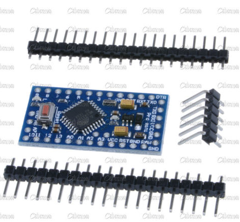
Hey I recently got a batch of ten pro 3.3v pro minis from ebay, I removed vreg + LED on two of them and they no longer work... Well, I cant upload. I have done this low power mod heaps of times, the boards are different from ones Ive seen before, has anyone here had this problem? Or am I just a problem magnet? Have yet to solder programming headers on a non modified board to see if its a bad batch... Maybe main power is routed through the vreg or LED regardless or something? I dont have the eyesight or mag abilities to play around...
-
Hey I recently got a batch of ten pro 3.3v pro minis from ebay, I removed vreg + LED on two of them and they no longer work... Well, I cant upload. I have done this low power mod heaps of times, the boards are different from ones Ive seen before, has anyone here had this problem? Or am I just a problem magnet? Have yet to solder programming headers on a non modified board to see if its a bad batch... Maybe main power is routed through the vreg or LED regardless or something? I dont have the eyesight or mag abilities to play around...
@Matt - I have killed some when i tried to remove them led/reg with a knife (ie cutting). So i began desoldering them which workes nice. I have killed one because of a short circuit and one because i damaged the pad.
Could be as you say another routing if its a new clone. Removing the led/resisotor led to being with should not affect this as it most likely only goes to ground.
-
@Matt - I have killed some when i tried to remove them led/reg with a knife (ie cutting). So i began desoldering them which workes nice. I have killed one because of a short circuit and one because i damaged the pad.
Could be as you say another routing if its a new clone. Removing the led/resisotor led to being with should not affect this as it most likely only goes to ground.
@sundberg84
Thanks for your reply. Given I've done six or seven to date without issue I am somewhat skeptical that I have borked two in a row. I use a fine tip hakko iron, solder sucker, wick + a tiny wee flathead screwdriver for the butchery.
Maybe its time I invested in a magnifying glass heh.
Is it necessary to remove the vreg as I would think its not doing anything anyway as we are powering via VCC rather than raw? -
@sundberg84
Thanks for your reply. Given I've done six or seven to date without issue I am somewhat skeptical that I have borked two in a row. I use a fine tip hakko iron, solder sucker, wick + a tiny wee flathead screwdriver for the butchery.
Maybe its time I invested in a magnifying glass heh.
Is it necessary to remove the vreg as I would think its not doing anything anyway as we are powering via VCC rather than raw?@Matt - Sounds strange. Magnifying glass is cheap and good :+1:
-
@Matt - Sounds strange. Magnifying glass is cheap and good :+1:
@sundberg84
Yeah it is a bit. As I said, may yet be a bad batch, too busy with other things right now to test a third one.
Mind you, just found this and as I suspected, there appears to be no point in removing the regulator if we are powering directly via vcc. -
Hey I recently got a batch of ten pro 3.3v pro minis from ebay, I removed vreg + LED on two of them and they no longer work... Well, I cant upload. I have done this low power mod heaps of times, the boards are different from ones Ive seen before, has anyone here had this problem? Or am I just a problem magnet? Have yet to solder programming headers on a non modified board to see if its a bad batch... Maybe main power is routed through the vreg or LED regardless or something? I dont have the eyesight or mag abilities to play around...
@Matt said:
Hey I recently got a batch of ten pro 3.3v pro minis from ebay, I removed vreg + LED on two of them and they no longer work... Well, I cant upload.
Did you try to use side pins for Vcc/Gnd connections from usb-ttl adapter? It is known for some clones that Vcc/Gnd pins on programming header do not work after regulator and led are removed and side pins must be used for uploading sketch...
-
Had further problems with intermittent sends. Sometimes on initial presentation it only sends the sketch name and not version number. Also sends are infrequent up to six hours apart. When it does send it often only sends one child_id when there are three to send.
Previously I thought this was most likely an issue with a noisy boost converter. However I just tried replacing the 4.7uf cap on the radio with a 47uf one. Problem solved!
Matt -
Had further problems with intermittent sends. Sometimes on initial presentation it only sends the sketch name and not version number. Also sends are infrequent up to six hours apart. When it does send it often only sends one child_id when there are three to send.
Previously I thought this was most likely an issue with a noisy boost converter. However I just tried replacing the 4.7uf cap on the radio with a 47uf one. Problem solved!
Matt@Matt - Nice to hear problem solved! Its again the sensitive radio and the booster might be the cause since changing the cap worked.
One trick is also to add a delay(10) between the presentations if possible. Sometimes the radio cant keep up or something...