💬 Sensebender Gateway
-
No, I haven't heard of any near plans in the core team about doing multi radio/sub-network support in 2.0.
This requires some extra thoughts and would probably only fit on SAMD/ESP nodes.
-
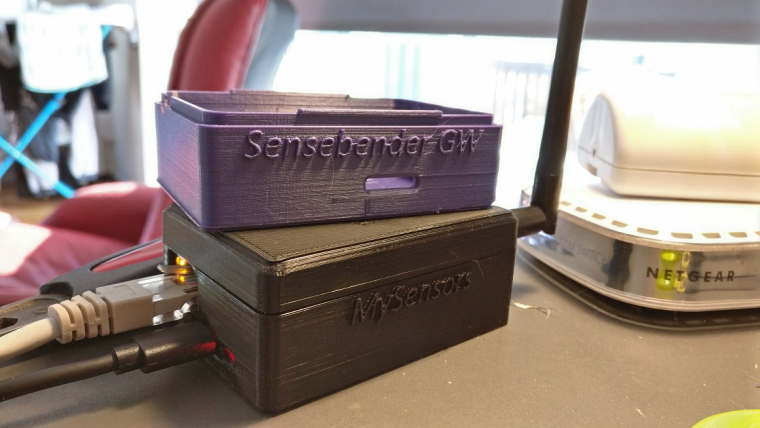
@NiklasO that looks very good!
Are you willing to share your design files with us?
i just ordered my gateway to get rid of cables and lose components :D a case would really make it complete! -
@NiklasO
great :+1:
@nick-van-alst
you can get enclosure design files here https://www.mysensors.org/hardware/sensebender-gateway (on page bottom)
I designed different variants so pick which one you need. -
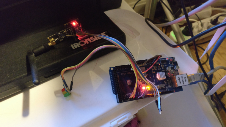
Ok i just connected the W5100 and NRF24 Module and uploaded the GatewayW5100 Sketch and when the upload is done after reset i dont get any output on serial monitor.
The orange, green and red led are lighting.When i upload the SensebenderGatewaySerial then i get output on serial monitor. It think the problem must be the w5100. But what going wrong?
@meddie said in 💬 Sensebender Gateway:
Ok i just connected the W5100 and NRF24 Module and uploaded the GatewayW5100 Sketch and when the upload is done after reset i dont get any output on serial monitor.
The orange, green and red led are lighting.When i upload the SensebenderGatewaySerial then i get output on serial monitor. It think the problem must be the w5100. But what going wrong?
@meddie Did you figure out what the problem is? I have exactly the same issue
-
@meddie said in 💬 Sensebender Gateway:
Ok i just connected the W5100 and NRF24 Module and uploaded the GatewayW5100 Sketch and when the upload is done after reset i dont get any output on serial monitor.
The orange, green and red led are lighting.When i upload the SensebenderGatewaySerial then i get output on serial monitor. It think the problem must be the w5100. But what going wrong?
@meddie Did you figure out what the problem is? I have exactly the same issue
@alexsh1
hi, yes it was very simple :-D the gateway has worked fine in this time, i thought that when nothing shown in serial monitor that the gateway dont work, but it did it, after i connected the gateway to FHEM (my controller) i saw that FHEM connects t mys Gateway.
So it worked all the timeGreets Eddie
-
@meddie said in 💬 Sensebender Gateway:
Ok i just connected the W5100 and NRF24 Module and uploaded the GatewayW5100 Sketch and when the upload is done after reset i dont get any output on serial monitor.
The orange, green and red led are lighting.When i upload the SensebenderGatewaySerial then i get output on serial monitor. It think the problem must be the w5100. But what going wrong?
@meddie Did you figure out what the problem is? I have exactly the same issue
-
Have you tried to enable the debug output in the GatewayW5100 example? I think it is disabled by default, due to the limited memory on the small atmega 328p
-
-
OK, I did manage to get debug working partially.
The gateway reads messages, but does not work as the gateway0;255;3;0;9;MCO:BGN:STP 0;255;3;0;9;MCO:BGN:INIT OK,TSP=1 0;255;3;0;9;TSF:MSG:READ,10-10-0,s=1,c=1,t=17,pt=5,l=4,sg=0:348 0;255;3;0;9;TSF:MSG:READ,26-10-0,s=3,c=1,t=24,pt=5,l=4,sg=0:51219479 0;255;3;0;9;TSF:MSG:READ,10-10-0,s=1,c=1,t=24,pt=5,l=4,sg=0:51219482 0;255;3;0;9;TSF:MSG:READ,11-11-0,s=2,c=1,t=37,pt=7,l=5,sg=0:1717.62 0;255;3;0;9;TSF:MSG:READ,11-11-0,s=0,c=1,t=37,pt=7,l=5,sg=0:5338.44 0;255;3;0;9;TSF:MSG:READ,11-11-0,s=3,c=1,t=37,pt=7,l=5,sg=0:10.75 0;255;3;0;9;TSF:MSG:READ,11-11-0,s=3,c=1,t=37,pt=7,l=5,sg=0:10.76 0;255;3;0;9;TSF:MSG:READ,11-11-0,s=4,c=1,t=37,pt=4,l=4,sg=0:880 0;255;3;0;9;TSF:MSG:READ,6-6-0,s=2,c=1,t=1,pt=7,l=5,sg=0:64.8 0;255;3;0;9;TSF:MSG:READ,6-6-0,s=0,c=1,t=4,pt=7,l=5,sg=0:1015I never had a message:
Gateway startup complete.EDIT: Self-test with SensebenderSerial sketch gives me this:
Sensebender GateWay test routine Mysensors core version : 2.1.1 GateWay sketch version : 0.2 ---------------------------------- - > SHA204 Failed to wakeup SHA204 - > SD CARD SD CARD did not initialize! -> EEPROM PASSED -> analog : 38 Failed -
Could you check the soldering of the samd?
SD card fails, if you haven't inserted a card, when running the self test.
I do not have the SD card so that's fine
The samd looks fine - no bridges etc
I can try to re-solder it with a hot fan
Do you think samd may be at fault even though the serial GW is working?Unfortunately, I do not have another Ethernet w5100 to try it. Probably have to order a new one
-
I know that @Anticimex had problems with one of the pre-production samples that we got from China, with various problems, that was solved with "reflowing" the samd with a hot air gun.. So it was just a thought, that it could be a bad solder joint..
The W5100 is using it's own dedicated SPI port, so even though that the radio works, doesn't mean that there couldn't be any solder problems around the samd pins for W5100.
We have 3 different SPI ports in use on the gateway, one for the MysX connector, one for radio / sdcard, and one for W5100..
@tbowmo I do not have the oven to reflow the whole board, but can mount / unmount or re-work certain components 0805 or 0603. Below this it is a pain in the a***
Another observation - The GW behaves like this with or without W5100 mounted.
Seems like an SPI problem to me. How can I wire W5100 to MYSX please and what shall I can in the sketch please? Thank for your help - very much appreciate it -
@tbowmo OK, I manage to find the answer here -
MYSX
D11 - MOSI
D12 - MISO
D13 - SCK
D14 -CS#define MY_SOFTSPI
#define MY_SOFT_SPI_SCK_PIN 13
#define MY_SOFT_SPI_MISO_PIN 12
#define MY_SOFT_SPI_MOSI_PIN 11
MY_RF24_CS_PIN 14
RF24_CE_PIN ???Am I correct?
-
My current config for nrf24l01+ and w5100 is as follows:
#define MY_GATEWAY_W5100

#if !defined(MY_W5100_SPI_EN) && !defined(ARDUINO_ARCH_SAMD)
#define MY_SOFTSPI
#define MY_SOFT_SPI_SCK_PIN 14
#define MY_SOFT_SPI_MISO_PIN 16
#define MY_SOFT_SPI_MOSI_PIN 15
#endif

#define MY_RF24_CE_PIN 5
#define MY_RF24_CS_PIN 6
Why CE / CS pins are 5 and 6?
Should that be 27 and 3?