💬 Sensebender Gateway
-
@MLs
I'm also still using win7 x64 for my dev and that worked for me.Auto install through the Device Manager does not work, nor right-clicking and installing the .inf through Explorer.
You have to force the install and select the location of the .inf in Device Manager. Then it will ask you if you agree about the driver supplier. Of course you're! And you should be able to see it in Device Manager.
-
@MLs
yep that's what i explained.
you need to force it in Device Manager. How you're doing in Device manager actually is rather auto, imho ;)
You can try in Device manager to right click on the bad detected device, here Sensebender Gw, and in properties, update driver. At a moment, it should prompt an "Open file" Dialog box (you need to choose the right option in the dialog) and then select your .inf file. And it will ask if you're ok to install a driver from a third party. -
There are example program for W5100? The original GatewayW5100 program uses SOFTSPI, different NRF CE/CSN pins? Will work with this hardware properly?
The standard GatewayW5100 example sketch will work on the sensebender gateway. There are conditional compile statements in that sketch, that disables softspi when compiling to the gateway target, and use a hardware SPI instead.
Remember to choose the correct target in your Arduino IDE
-
@MLs
Okay, simpler, forget what i told you, and follow my steps below. I've unstalled mine to show you ;)
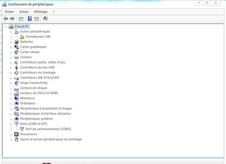
Then if it can be useful for others. Nothing fancy here, it can be used for lot of others drivers.Step 1: plugin the GW, as you can see it's not detected, and no additional com port.
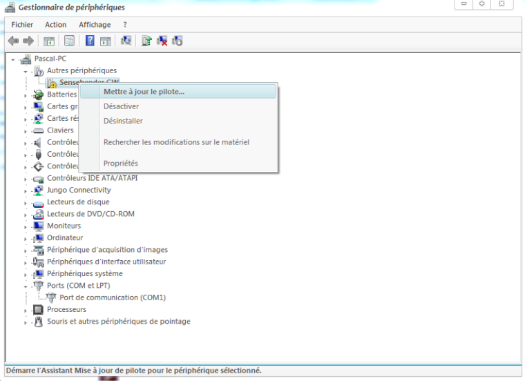
Step 2: right clic, and update driver
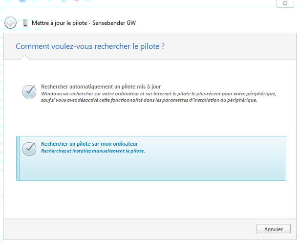
Step 3: click on the 2nd option for searching a driver on your machine
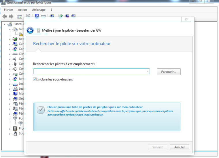
Step 4: Again 2nd option here (you want to search for a driver on your computer)
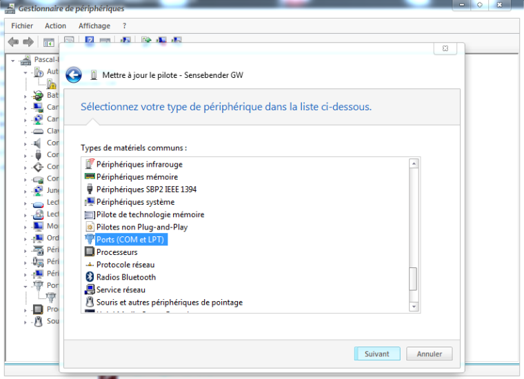
Step 5: This is a Virtual Serial Com port needed for the GW. So choose COM/LPT for the driver type
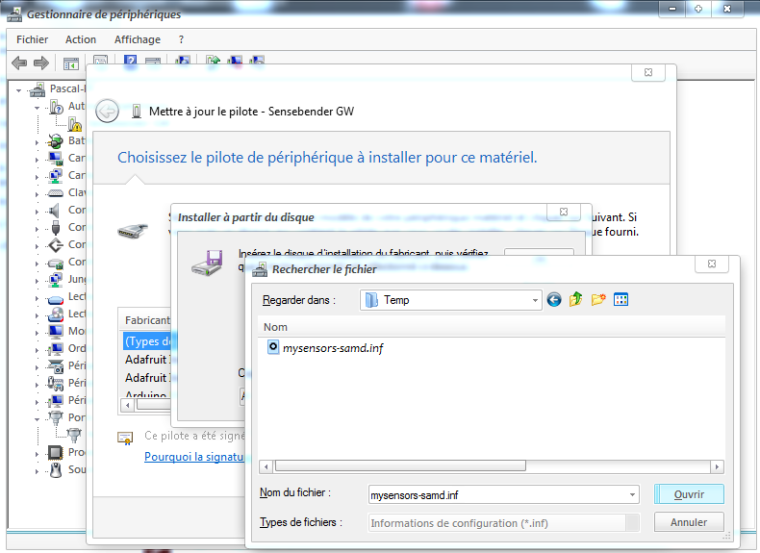
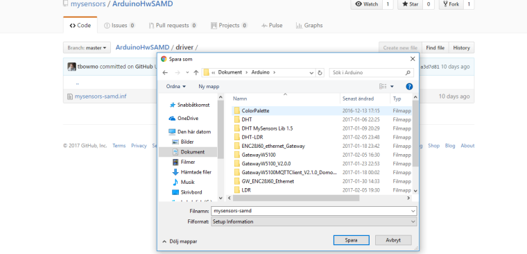
Step 6: Now it is asking where the driver (.inf) is stored
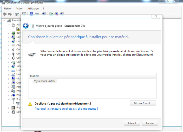
Step 7: You can now see that Windows knows what this is about. And tells you this driver is not "signed". No problem we know @tbowmo has done a great job. So, Next!
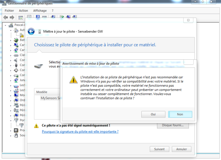
Step 8: Windows here warns again, saying he doesn't know this driver, so it may not work well. No way, it will work well ;) Click "Yes" to install it.
Step 9: Looks good
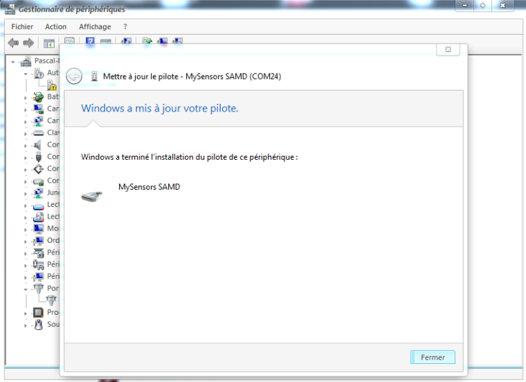
Step 10: Tada! Here you can see now the GW is well detected and setup on COM port 24
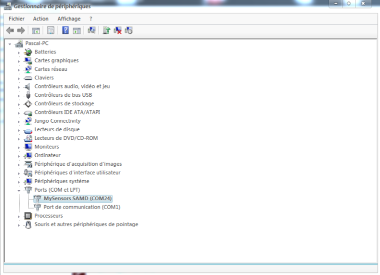
I can't do better!
I think you'll get it :) -
@MLs
Okay, simpler, forget what i told you, and follow my steps below. I've unstalled mine to show you ;)
Then if it can be useful for others. Nothing fancy here, it can be used for lot of others drivers.Step 1: plugin the GW, as you can see it's not detected, and no additional com port.
Step 2: right clic, and update driver
Step 3: click on the 2nd option for searching a driver on your machine
Step 4: Again 2nd option here (you want to search for a driver on your computer)
Step 5: This is a Virtual Serial Com port needed for the GW. So choose COM/LPT for the driver type
Step 6: Now it is asking where the driver (.inf) is stored
Step 7: You can now see that Windows knows what this is about. And tells you this driver is not "signed". No problem we know @tbowmo has done a great job. So, Next!
Step 8: Windows here warns again, saying he doesn't know this driver, so it may not work well. No way, it will work well ;) Click "Yes" to install it.
Step 9: Looks good
Step 10: Tada! Here you can see now the GW is well detected and setup on COM port 24
I can't do better!
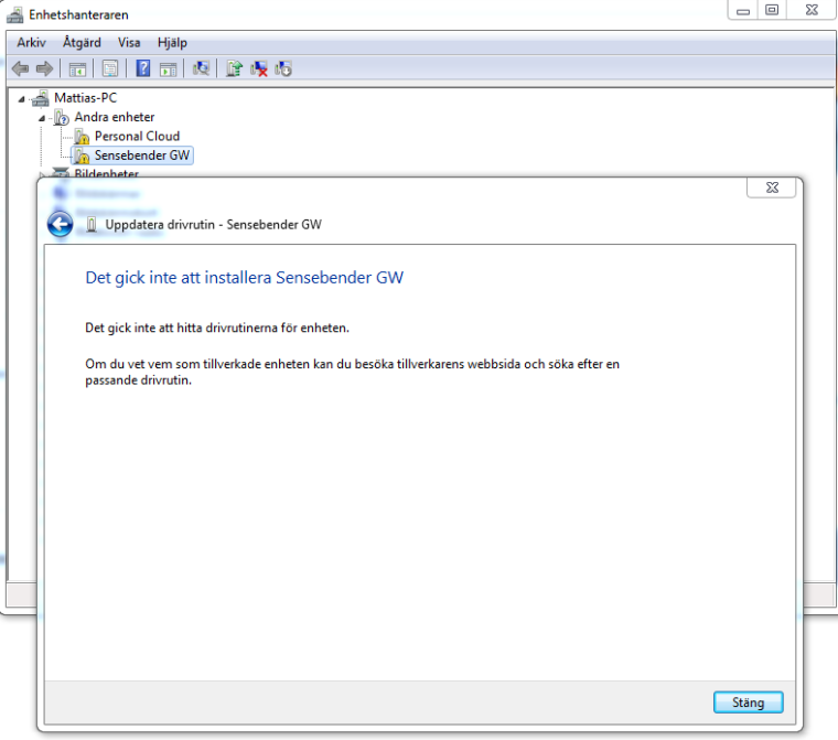
I think you'll get it :)Thanks for a super instruction but it is the file itself that the computer says from. It says that the folder contains the no driver
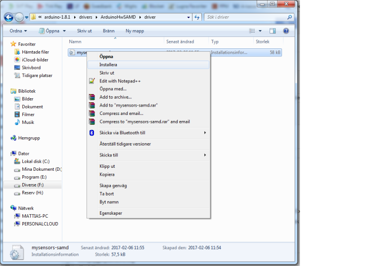
And the driver in the folder I chose I downloaded here
https://github.com/mysensors/ArduinoHwSAMD/blob/master/driver/mysensors-samd.inf
// Mattias
-
Thanks for a super instruction but it is the file itself that the computer says from. It says that the folder contains the no driver
And the driver in the folder I chose I downloaded here
https://github.com/mysensors/ArduinoHwSAMD/blob/master/driver/mysensors-samd.inf
// Mattias
-
-
No, that will download a github html page.
Use the link I posted (and save as). It will be the raw content.
-
No, that will download a github html page.
Use the link I posted (and save as). It will be the raw content.
Now, I also got the computer to recognize the card. Thanks for all help.
The problem was that even when I used save as, the computer renaming the file as a .txt file "mysensors-samd.inf.txt" and not a "mysensors-samd.inf"
Again, thanks for all the help.
//Mattias
-
Hi together,
i have some questions to you! I bought a sensebender gateway and a w5100 Ethernet Modul, but i cant get it to work. When i upload the Gateway5100 Sketch and put my yip address in it, then the GW is booting up i get some Data on the serial port but i cant ping the configured ip address. Then i tried to config via DHCP and see that the GW dont get an IP Address.
And when i connect the NRF24 Modul then it seems that the GW is not bootin up anymore because i dont get any data on serial port.
i need your help. Thanks a lot in advance -
Hi tbowmo,
with the gatewayw5100 Sketch i get every 10 seconds 5 lines output on serial monitor:
The sketch is default i changed only the ip adress0;255;3;0;9;TSM:FAIL:RE-INIT 0;255;3;0;9;TSM:INIT 0;255;3;0;9;!TSM:INIT:TSP FAIL 0;255;3;0;9;TSM:FAIL:CNT=3 0;255;3;0;9;TSM:FAIL:PDT 0;255;3;0;9;TSM:FAIL:RE-INIT 0;255;3;0;9;TSM:INIT 0;255;3;0;9;!TSM:INIT:TSP FAIL 0;255;3;0;9;TSM:FAIL:CNT=4 0;255;3;0;9;TSM:FAIL:PDT 0;255;3;0;9;TSM:FAIL:RE-INIT 0;255;3;0;9;TSM:INIT 0;255;3;0;9;!TSM:INIT:TSP FAIL 0;255;3;0;9;TSM:FAIL:CNT=5 0;255;3;0;9;i dont know why, but i just uploaded the sensebenderserialgateway sketch and now i get this output:
0;255;3;0;9;MCO:BGN:INIT GW,CP=RNNGS--,VER=2.1.1
0;255;3;0;9;TSF:LRT:OK
0;255;3;0;9;TSM:INIT
0;255;3;0;9;TSF:WUR:MS=0
0;255;3;0;9;TSM:INIT:TSP OK
0;255;3;0;9;TSM:INIT:GW MODE
0;255;3;0;9;TSM:READY:ID=0,PAR=0,DIS=0
0;255;3;0;9;MCO:REG:NOT NEEDED
0;255;3;0;14;Gateway startup complete.
0;255;0;0;18;2.1.1
0;255;3;0;9;MCO:BGN:STP
0;255;3;0;9;
the NRF Module is connected! Now i need to get the w5100 module to work.
-
Ok i just connected the W5100 and NRF24 Module and uploaded the GatewayW5100 Sketch and when the upload is done after reset i dont get any output on serial monitor.
The orange, green and red led are lighting.When i upload the SensebenderGatewaySerial then i get output on serial monitor. It think the problem must be the w5100. But what going wrong?
-
i have only changed the ip adress
here is the sketch:/** * The MySensors Arduino library handles the wireless radio link and protocol * between your home built sensors/actuators and HA controller of choice. * The sensors forms a self healing radio network with optional repeaters. Each * repeater and gateway builds a routing tables in EEPROM which keeps track of the * network topology allowing messages to be routed to nodes. * * Created by Henrik Ekblad <henrik.ekblad@mysensors.org> * Copyright (C) 2013-2015 Sensnology AB * Full contributor list: https://github.com/mysensors/Arduino/graphs/contributors * * Documentation: http://www.mysensors.org * Support Forum: http://forum.mysensors.org * * This program is free software; you can redistribute it and/or * modify it under the terms of the GNU General Public License * version 2 as published by the Free Software Foundation. * ******************************* * * REVISION HISTORY * Version 1.0 - Henrik EKblad * Contribution by a-lurker and Anticimex, * Contribution by Norbert Truchsess <norbert.truchsess@t-online.de> * Contribution by Tomas Hozza <thozza@gmail.com> * * * DESCRIPTION * The EthernetGateway sends data received from sensors to the ethernet link. * The gateway also accepts input on ethernet interface, which is then sent out to the radio network. * * The GW code is designed for Arduino 328p / 16MHz. ATmega168 does not have enough memory to run this program. * * LED purposes: * - To use the feature, uncomment MY_DEFAULT_xxx_LED_PIN in the sketch below * - RX (green) - blink fast on radio message recieved. In inclusion mode will blink fast only on presentation recieved * - TX (yellow) - blink fast on radio message transmitted. In inclusion mode will blink slowly * - ERR (red) - fast blink on error during transmission error or recieve crc error * * See http://www.mysensors.org/build/ethernet_gateway for wiring instructions. * */ // Enable debug prints to serial monitor #define MY_DEBUG // Enable and select radio type attached #define MY_RADIO_NRF24 //#define MY_RADIO_RFM69 // Enable gateway ethernet module type #define MY_GATEWAY_W5100 // W5100 Ethernet module SPI enable (optional if using a shield/module that manages SPI_EN signal) //#define MY_W5100_SPI_EN 4 // Enable Soft SPI for NRF radio (note different radio wiring is required) // The W5100 ethernet module seems to have a hard time co-operate with // radio on the same spi bus. #if !defined(MY_W5100_SPI_EN) && !defined(ARDUINO_ARCH_SAMD) #define MY_SOFTSPI #define MY_SOFT_SPI_SCK_PIN 14 #define MY_SOFT_SPI_MISO_PIN 16 #define MY_SOFT_SPI_MOSI_PIN 15 #endif // When W5100 is connected we have to move CE/CSN pins for NRF radio #ifndef MY_RF24_CE_PIN #define MY_RF24_CE_PIN 5 #endif #ifndef MY_RF24_CS_PIN #define MY_RF24_CS_PIN 6 #endif // Enable to UDP //#define MY_USE_UDP #define MY_IP_ADDRESS 10,0,0,253 // If this is disabled, DHCP is used to retrieve address // Renewal period if using DHCP //#define MY_IP_RENEWAL_INTERVAL 60000 // The port to keep open on node server mode / or port to contact in client mode #define MY_PORT 5003 // Controller ip address. Enables client mode (default is "server" mode). // Also enable this if MY_USE_UDP is used and you want sensor data sent somewhere. //#define MY_CONTROLLER_IP_ADDRESS 192, 168, 178, 254 // The MAC address can be anything you want but should be unique on your network. // Newer boards have a MAC address printed on the underside of the PCB, which you can (optionally) use. // Note that most of the Ardunio examples use "DEAD BEEF FEED" for the MAC address. #define MY_MAC_ADDRESS 0xDE, 0xAD, 0xBE, 0xEF, 0xFE, 0xED // Enable inclusion mode #define MY_INCLUSION_MODE_FEATURE // Enable Inclusion mode button on gateway //#define MY_INCLUSION_BUTTON_FEATURE // Set inclusion mode duration (in seconds) #define MY_INCLUSION_MODE_DURATION 60 // Digital pin used for inclusion mode button //#define MY_INCLUSION_MODE_BUTTON_PIN 3 // Set blinking period #define MY_DEFAULT_LED_BLINK_PERIOD 300 // Flash leds on rx/tx/err // Uncomment to override default HW configurations //#define MY_DEFAULT_ERR_LED_PIN 7 // Error led pin //#define MY_DEFAULT_RX_LED_PIN 8 // Receive led pin //#define MY_DEFAULT_TX_LED_PIN 9 // Transmit led pin #if defined(MY_USE_UDP) #include <EthernetUdp.h> #endif #include <Ethernet.h> #include <MySensors.h> void setup() { } void loop() { }``` -
i have only changed the ip adress
here is the sketch:/** * The MySensors Arduino library handles the wireless radio link and protocol * between your home built sensors/actuators and HA controller of choice. * The sensors forms a self healing radio network with optional repeaters. Each * repeater and gateway builds a routing tables in EEPROM which keeps track of the * network topology allowing messages to be routed to nodes. * * Created by Henrik Ekblad <henrik.ekblad@mysensors.org> * Copyright (C) 2013-2015 Sensnology AB * Full contributor list: https://github.com/mysensors/Arduino/graphs/contributors * * Documentation: http://www.mysensors.org * Support Forum: http://forum.mysensors.org * * This program is free software; you can redistribute it and/or * modify it under the terms of the GNU General Public License * version 2 as published by the Free Software Foundation. * ******************************* * * REVISION HISTORY * Version 1.0 - Henrik EKblad * Contribution by a-lurker and Anticimex, * Contribution by Norbert Truchsess <norbert.truchsess@t-online.de> * Contribution by Tomas Hozza <thozza@gmail.com> * * * DESCRIPTION * The EthernetGateway sends data received from sensors to the ethernet link. * The gateway also accepts input on ethernet interface, which is then sent out to the radio network. * * The GW code is designed for Arduino 328p / 16MHz. ATmega168 does not have enough memory to run this program. * * LED purposes: * - To use the feature, uncomment MY_DEFAULT_xxx_LED_PIN in the sketch below * - RX (green) - blink fast on radio message recieved. In inclusion mode will blink fast only on presentation recieved * - TX (yellow) - blink fast on radio message transmitted. In inclusion mode will blink slowly * - ERR (red) - fast blink on error during transmission error or recieve crc error * * See http://www.mysensors.org/build/ethernet_gateway for wiring instructions. * */ // Enable debug prints to serial monitor #define MY_DEBUG // Enable and select radio type attached #define MY_RADIO_NRF24 //#define MY_RADIO_RFM69 // Enable gateway ethernet module type #define MY_GATEWAY_W5100 // W5100 Ethernet module SPI enable (optional if using a shield/module that manages SPI_EN signal) //#define MY_W5100_SPI_EN 4 // Enable Soft SPI for NRF radio (note different radio wiring is required) // The W5100 ethernet module seems to have a hard time co-operate with // radio on the same spi bus. #if !defined(MY_W5100_SPI_EN) && !defined(ARDUINO_ARCH_SAMD) #define MY_SOFTSPI #define MY_SOFT_SPI_SCK_PIN 14 #define MY_SOFT_SPI_MISO_PIN 16 #define MY_SOFT_SPI_MOSI_PIN 15 #endif // When W5100 is connected we have to move CE/CSN pins for NRF radio #ifndef MY_RF24_CE_PIN #define MY_RF24_CE_PIN 5 #endif #ifndef MY_RF24_CS_PIN #define MY_RF24_CS_PIN 6 #endif // Enable to UDP //#define MY_USE_UDP #define MY_IP_ADDRESS 10,0,0,253 // If this is disabled, DHCP is used to retrieve address // Renewal period if using DHCP //#define MY_IP_RENEWAL_INTERVAL 60000 // The port to keep open on node server mode / or port to contact in client mode #define MY_PORT 5003 // Controller ip address. Enables client mode (default is "server" mode). // Also enable this if MY_USE_UDP is used and you want sensor data sent somewhere. //#define MY_CONTROLLER_IP_ADDRESS 192, 168, 178, 254 // The MAC address can be anything you want but should be unique on your network. // Newer boards have a MAC address printed on the underside of the PCB, which you can (optionally) use. // Note that most of the Ardunio examples use "DEAD BEEF FEED" for the MAC address. #define MY_MAC_ADDRESS 0xDE, 0xAD, 0xBE, 0xEF, 0xFE, 0xED // Enable inclusion mode #define MY_INCLUSION_MODE_FEATURE // Enable Inclusion mode button on gateway //#define MY_INCLUSION_BUTTON_FEATURE // Set inclusion mode duration (in seconds) #define MY_INCLUSION_MODE_DURATION 60 // Digital pin used for inclusion mode button //#define MY_INCLUSION_MODE_BUTTON_PIN 3 // Set blinking period #define MY_DEFAULT_LED_BLINK_PERIOD 300 // Flash leds on rx/tx/err // Uncomment to override default HW configurations //#define MY_DEFAULT_ERR_LED_PIN 7 // Error led pin //#define MY_DEFAULT_RX_LED_PIN 8 // Receive led pin //#define MY_DEFAULT_TX_LED_PIN 9 // Transmit led pin #if defined(MY_USE_UDP) #include <EthernetUdp.h> #endif #include <Ethernet.h> #include <MySensors.h> void setup() { } void loop() { }```So I think i have a maybe already solved issue, but I can not get int working...
In Arduino IDE 1.8.1 this is the error during compiling:"Local\Arduino15\packages\arduino\hardware\samd\1.6.12\cores\arduino/Arduino.h:48:17: fatal error: sam.h: No such file or directory"
-
I have the MySensors SAMD boards installed, so Sensbender Gateway is availabe
-
Arduino SAMD boards are also installed
-
I have installed the "M0" boards
-
Running windows 10 so no need for the inf file, is this correct?
what am I missing?
thanks in advance!
-
Hello! It looks like you're interested in this conversation, but you don't have an account yet.
Getting fed up of having to scroll through the same posts each visit? When you register for an account, you'll always come back to exactly where you were before, and choose to be notified of new replies (either via email, or push notification). You'll also be able to save bookmarks and upvote posts to show your appreciation to other community members.
With your input, this post could be even better 💗
Register Login