[SOLVED] Very Bad Receiving Performance of Node when Powered by Buck Converter
-
Hello all,
I have a strange problem with my blinds controller node.
When I power my electronics through my computer with a FTDI programmer plugged into the 3.3V Arduino Pro Mini, everything works flawlessly. Receiving and sending messages both almost never fails, even through 2 walls.
But as soon as I power the device with a mains power supply (230V to 12V power supply --> 12V to 3.3V buck converter) without even changing the position of the module, the communication from gateway to the node is so bad that I sometimes need up to 5 tries till a message eventually is received by the node. Sending is still flawless, every message from blinds controller to gateway comes through first try.
I actually tried switching the 230V to 12V power supply against another model and still the same problem. I also measured the output of my FTDI programmer and it actually provides 3,48V and not 3,3V, so I tuned the buck converter to the same exact value. Still no better receiving results. I also switched my transceiver to make sure that this is not the problem.
I have a 47µF condenser soldered directly next to the NRF24L01+.
Could it be that my buck converter is faulty or that it is not the best type for this job? It says in the description that it has a switching frequency of 150kHz which seems pretty low compared to the 8 MHz of the Arduino. Strangely enough I built a LED dimming node with the same hardware and it works flawlessly.
Has anybody else seen some similar behaviour on one of their nodes? I am baffled because sending works perfectly but receiving quality is completely dependent on power source.
Thanks in advance for every bit of help!
-
The nrf24 module is very sensitive to power issues.
Sometimes it can make a different to try different caps on the radio between VCC and GND.
For example my GW i use a 4,7uf and a 47uF paralel. -
As I understand it the cap only keeps the power supply of the transceiver up when it is consuming power by sending messages. So because I have receiving problems I checked it off as not the source of my problems.
But I will give it a try also soldering a smaller cap onto the board. -
Good point... and a strange problem but since you have located the problem to your power source I would give it a try as well.
Maybe someone with greater knowledge in the nrf module can give you some better answers. -
I use the same converter with no issues at all. Make sure that your grounding is well connected and maybe try a smaller cap or/and a small ceramic cap.
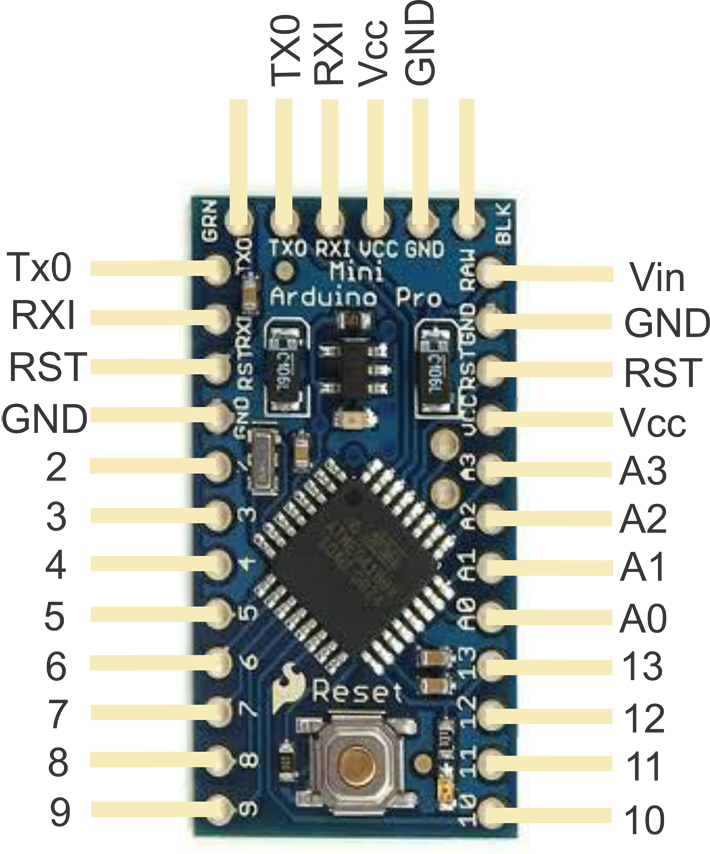
@Oitzu Hm now I'm actually not sure how I grounded everything. It could very well be that I have soldered the power supply to the GND pin next to the RAW input and the transceiver to the GND pin next to digital pin 2 without connecting the two together. So while connected to an FTDI programmer the GND pin of the transceiver is grounded properly whereas powering it through the step down converter gives me grounding problems. Could this be an issue or are all the GND pins of the arduino properly interconnected internally?

And another question: Currently my buck converter is connected to the Vcc pin of the arduino and also the Vcc pin of the transceiver. What if I would supply the RAW pin of my arduino with, let's say 5V from my buck converter and I would then draw the 3.3 V for my transceiver from the Vcc pin of the Arduino through its internal step down converter? This would probably resemble the FTDI programmer power supply a little bit more even though it would be more inefficient.
-
@Oitzu Hm now I'm actually not sure how I grounded everything. It could very well be that I have soldered the power supply to the GND pin next to the RAW input and the transceiver to the GND pin next to digital pin 2 without connecting the two together. So while connected to an FTDI programmer the GND pin of the transceiver is grounded properly whereas powering it through the step down converter gives me grounding problems. Could this be an issue or are all the GND pins of the arduino properly interconnected internally?

And another question: Currently my buck converter is connected to the Vcc pin of the arduino and also the Vcc pin of the transceiver. What if I would supply the RAW pin of my arduino with, let's say 5V from my buck converter and I would then draw the 3.3 V for my transceiver from the Vcc pin of the Arduino through its internal step down converter? This would probably resemble the FTDI programmer power supply a little bit more even though it would be more inefficient.
@Mathea90 I directly connected "output -" to Arduino GND and nrf24l01+ GND, and "output +" directly to Arduino VCC and nrf24l01+ VCC.
Could this be an issue or are all the GND pins of the arduino properly interconnected internally?
The grounds of the arduino should normally properly interconnected. But i would give it a try.
draw the 3.3 V for my transceiver from the Vcc pin of the Arduino through its internal step down converter?
Could be done with the small nrf24l01+ modules. But i wouldn't do it. It's, as said, inefficient.
-
First, I'm not expert, but I always want the best for my toys..so I have read lot of things to improve my routing, performance of my boards... even if my proto works rather well.
There are lot of things which can affect radio performance and rssi, especially when using switching regulators, I won't enumerate everything, but it is the very first and important point :
- A bad ground of course, even with ldo. Without good gnd, no good antenna.
- a bad switching reg design
- bad pcb design when homemade
- Another one, but not the least, the arduino/breadboarding wiring style. Having wire between boards increase negative effects of switching and ripples, and acts like an antenna too. And with EMI you get a great destructive combo for antenna. So sometimes it works, sometimes not at its best, and sometimes where is the bug???
So, now for these reasons, on my latest dev, I add ferrite beads, capa filtering, on my circuit.When I will receive my new rev, I will look what difference it makes, but I think it should make one (I hope). Ah, and I don't put the switching reg near my radio circuit of course ;)
Maybe, it has nothing to do with your problem, but I hope it can help a little.
-
Thanks for all the input from you guys. Immediately when I'm home I will check some of those ideas.
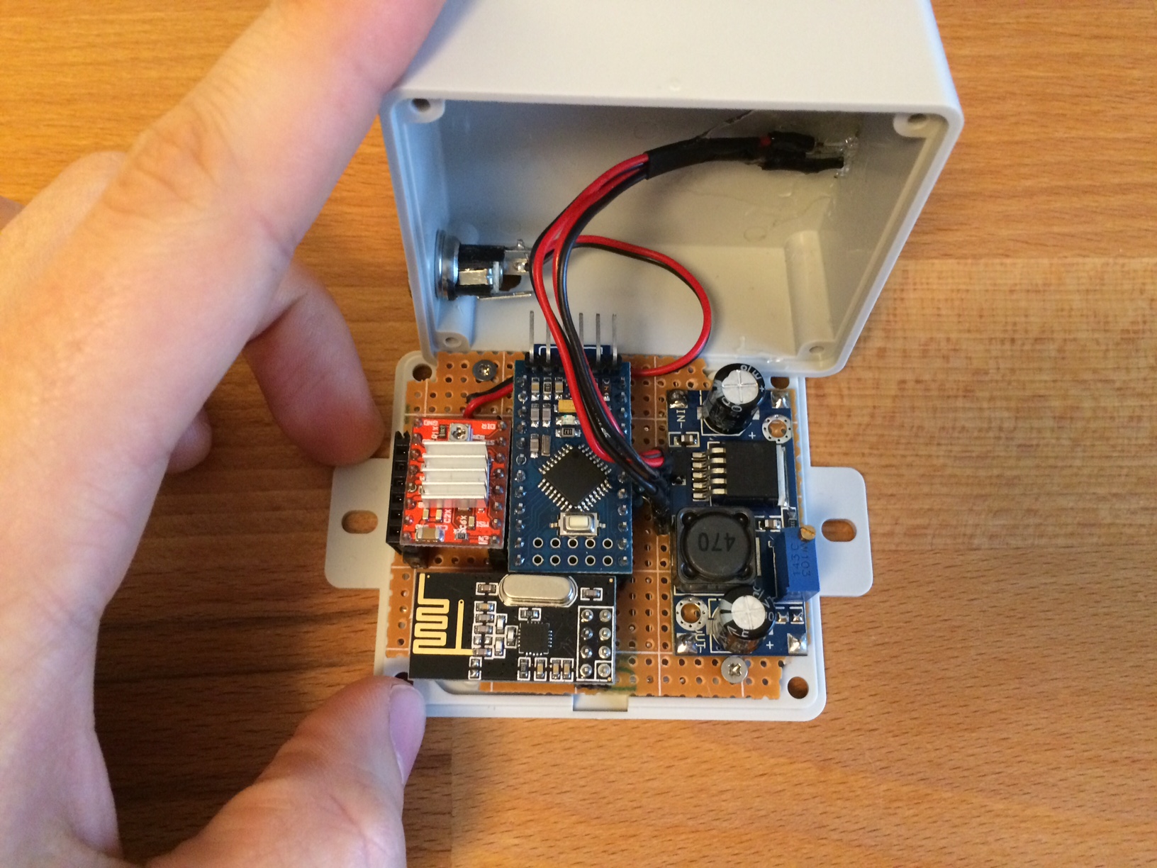
Just so you can make yourselves a picture of how my electronics looks like:

The red thingy is my stepper motor driver. Unfortunately I have no picture of the backside with the soldering work at hand but I don't know if this would be helpful.
I tried building the system as compact as possible while still keeping some possibility to swap components easily. So the spacing of the modules is a little bit cramped together.
As soon as I have a look on my wiring I will update how I actually did the grounding.
Edit: the 47µF capacitor is sitting directly under the transceiver in a lying position.
-
Guys, I found a solution for my problem! I tried everything from soldering the two GND pins of the Arduino together to an additional small condenser but nothing worked.
So just for the heck of it I connected my buck converter to the RAW pin of the Arduino and adjusted it to something between 3,5 and 4V. Now my stepper driver and the transceiver both are supplied with power from the Arduino VCC pin and it works 100% reliable. So my conclusion is that the Step down converter of the Arduino conditions the 3.3V better than the buck Converter and this solved all my receiving problems.
I don't like that I now have an additional conversion step in my power supply but honestly at this moment I don't bother anymore because I'm just happy to have it finally working.
I thank you all very much for your Input!
