💬 AC-DC double solid state relay module


  • Hardware Contributor

    @tonnerre33
    I have made a board for tshutters 😉
    on my side, it's completed. I'm actually checking files, writing docs for my git (bom etc..) I have so much projects almost completed to show so I have to clean my projects one by one 😣 and I don't talk about software stuff too..arghh!
    Here it is https://forum.mysensors.org/topic/2944/roller-shutter-node


  • Hardware Contributor

    Yes, i know this good project but he don't use an arduino pro mini like Aproxx 😉
    Your project need welding cms and i never do it ^^
    The Aproxx's board has Thermal Cutoffs, and i didn't see that in your project


  • Hardware Contributor

    @tonnerre33 yep. you're right, it's cms I'm sorry 😞 I think.. good luck to fit everything with arduino mini in wall.
    About the cutoff, I replaced this by a simple temperature sensor for monitoring. imho, i have two fuses onboards + varistor, enough for me comparing to some commercial products. If it burns you have a big problem somewhere!! But sure it's better to know what you do, thermal fuses is good 😉


  • Hardware Contributor

    @scalz don't be sorry, i just need to learn to weld cms xd But for not disturb this project, i'll continue ta ask my questions in your topic project 😉


  • Hardware Contributor

    @tonnerre33 said:

    But for command up/down, and in order to do an hardware protection, we can use an inversor relay.
    I don't know if we need an inversor relay. For sure it will be hard to find another relay as small as these SSRs
    Maybe I'm wrong but I from what I know roller shutter motors have a common ground and then you connect the phase for the direction you want to use. I think it can be done in software, with hardware it cannot be done on this PCB because of the way the SSRs are connected.

    @scalz on your board you use relays that are much bigger than those tiny SSRs, in the end it probably gives the same result for the space used on the board, and as you have the radio on the other side the depth difference is not very big, just 2mm from the plastic at the base of the connectors.


  • Hi I did everything according to the project and I have problem "error sending the switch command check device / hardware"
    One change for me is 10nF capacitor instead of 100nF (I dont have now
    )
    Could this be the reasons this error?!
    0_1470516115940_ERROR.JPG


  • Hardware Contributor

    @okos if you have the device in Domoticz it means it could run, and send data to the gateway controller.
    Did you change anything in hardware of software between the moment you added the node/sensor to Domoticz and the moment you tried to activate it ?
    Are you sure your settings for the ACK are ok ? Maybe you are not sending one in the node but waiting from one in Domoticz ? Check the "Ack" column in Domoticz and if it's true try to change it to false.


  • Aproxx you roxx. It works! Not sure what to do with it yet, but likely it will end up in a wall sometime soon on light duties. Thanks for sharing such a great design 🙂
    0_1470565848624_IMG_20160807_222603-800x735.jpg
    Hmm just pulled some switches, they are mostly SPDT jobbies on multiple switches, no idea how to hood this bad-boy up =(


  • Hi everyone,

    First I would like to thank the OP for sharing this great project 🙂

    Then I would like to ask what would happen if the node cannot connect to the gateway on startup? It would still be possible to use the switch?

    Thank you,


  • Hardware Contributor

    @Daniel-Oliveira said:

    Then I would like to ask what would happen if the node cannot connect to the gateway on startup? It would still be possible to use the switch?

    Hello, on startup if it cannot connect to gateway MySensors library will loop until it connects, so no. But once started as you have direct connection to the switch it will work even if the gateway fails.


  • @Nca78 Thank you for the reply,

    There is a way to overcame that? Like add a max retry of sorts? My concern is that if by some reason the gateway fails and the node reboots I will not be able use the switch.

    Or does MySensors have another fail safe mechanism that I'm not aware?


  • Hardware Contributor

    No that I know.
    But this situation is really unlikely, nodes are very stable usually (else you'll quickly see a problem). Basically you would need the gateway to fail, then a power outage to reboot your node.


  • @Nca78 said:

    @okos if you have the device in Domoticz it means it could run, and send data to the gateway controller.
    Did you change anything in hardware of software between the moment you added the node/sensor to Domoticz and the moment you tried to activate it ?
    Are you sure your settings for the ACK are ok ? Maybe you are not sending one in the node but waiting from one in Domoticz ? Check the "Ack" column in Domoticz and if it's true try to change it to false.

    Thanks for the answer 😃 Nca78, but I do not know where to look for settings Ack.
    Please help


  • Hardware Contributor

    @okos go to Setup menu / Hardware, then click on the "Setup" button for your MySensors gateway.
    In the top list select the node, and in the bottom you will see the sensors attached to this node, and a Ack column for each sensor. To edit the ack column just select item and you have the checkbox below the grid with update button.


  • This post is deleted!

  • Hardware Contributor

    First board soldered and tested, it runs very well, thank you for the great work @aproxx !
    Thank you @Konstantin-Kolesnichenko also for adapting the script to version 2.0.

    I just didn't dare to install the ds18b20, the tiny distance to the temp fuse pad gives me some nightmares 😰 so I prefer having no temperature sensor and put a piece of insulating tape on both sides.
    This one will go in the ceiling, but for next board I will keep the vcc pin of the NRF24 and change a bit the code to use touch sensors behind a livolo glass plate. I need some top level WAF before I can go on with the MySensorization of all the appartment 😄

    0_1471537898596_SSR_Relay_Board.jpg (like the others I will not show the back side and it's ugly pieces of insulating tape :D)

    @okos did you fix your problem ? I see your deleted message.


  • @okos did you fix your problem ? I see your deleted message.

    Now everything is ok.
    Nrf changed, and changed the position of the gate (it is now above - on the fridge :))

    But I have another problem
    I used the code from Konstantin Kolesnichenko (thanks), and even after the power is changing relay.

    Example:

    on relay 1
    off Relay 2

    turn off the power, and after power returning I

    on relay 2
    off Relay 1

    Why exchange ?


  • Hardware Contributor

    @okos I will try to do more tests tomorrow to see if I have the same problem. I see no obvious mistake in the script that would generate this though. The only thing I see would be if you have linked your module with physical switches and they are in different position. As the script assumes that at startup the buttons are in "off" position (circuit opened).

    I think we should have this code at the end of the setup() method to initialize the oldValue and oldValue2 variables.

      // Set the initial values of oldValue/oldValue2 variables from status of physical switches
      debouncer.update();
      debouncer2.update();
      oldValue = debouncer.read();
      oldValue2 = debouncer2.read();
    

  • Hardware Contributor

    @okos I confirm to you that without the change in my previous message, I had a similar problem (relay 1 always on and relay 2 always off at startup). After applying the change I don't have any problem on restart, it was just an initialization problem.
    I'm making some small improvements to the sketch, I will test tomorrow and post it.


  • Thanks Nca78, I'm waiting for a revised code


  • Hardware Contributor

    Hello,
    this is the updated code, the list of changes at the top of the script.
    In short :

    • fixed initialization of hardware buttons
    • improved debug information
    • made temperature sensor optional (via a #define) as I think it's location on the board is not safe

    I think the behavior of the node is fine now, it has debug for physical buttons and the script uses less program space (<12k, <8k if temp sensor is disabled: you can enable debug even with an old atmega168 pro mini :)) and less ram (514 bytes for global variables).

    I added the temp sensor on my first board to make some tests, it's in the ceiling now in a big (10x10cm) but air-tight electric box. Both relays are switched off at the moment and I'm waiting for the temperature to stabilize, then I will try to switch the loads on and off, leave on for a long time etc etc. 28W light tube on first relay, 2x28W on the other, it should not create problem.

    /**
     * The MySensors Arduino library handles the wireless radio link and protocol
     * between your home built sensors/actuators and HA controller of choice.
     * The sensors forms a self healing radio network with optional repeaters. Each
     * repeater and gateway builds a routing tables in EEPROM which keeps track of the
     * network topology allowing messages to be routed to nodes.
     *
     * Created by Henrik Ekblad <henrik.ekblad@mysensors.org>
     * Copyright (C) 2013-2015 Sensnology AB
     * Full contributor list: https://github.com/mysensors/Arduino/graphs/contributors
     *
     * Documentation: http://www.mysensors.org
     * Support Forum: http://forum.mysensors.org
     *
     * This program is free software; you can redistribute it and/or
     * modify it under the terms of the GNU General Public License
     * version 2 as published by the Free Software Foundation.
     *
     *******************************
     *
     * DESCRIPTION
     *
     * Script for double SSR relay board by Aproxx
     * https://www.openhardware.io/view/77/AC-DC-double-solid-state-relay-module
     * https://forum.mysensors.org/topic/3671/ac-dc-double-solid-state-relay-module
     * Control 2 circuits either from controller or from physical buttons connected on pins 4 & 7
     * Optional DS18b20 is connected on pin 8
     * 
     *  HISTORY :
     * xx/xx/2016 original version by Aproxx
     * 08/02/2016 upgraded to MySensors 2.0 by mr_const
     * 08/30/2016 changes by Nca78 :
     *        - fixed initialization of physical buttons/debouncer status
     *        - centralized pin status change for relays in setRelayState method
     *        - centralized debug information for state changes in one method + added debug info when changed by physical switches
     *        - added #ifdef MY_DEBUG before each Serial.print (saves prog memory when not in debug mode) and F() macros for debug strings (saves RAM when in debug mode)
     *        - added #define USE_TEMP_SENSOR to make temperature sensor optional (not used if line is commented)
     *        - put back #define for repeater feature
     *        - add #define TEMPERATURE_ROUNDING for custom temperature rounding
    **/
    
    // MySensor Debug
    //#define MY_DEBUG
    
    // Enables repeater functionality (relays messages from other nodes)
    //#define MY_REPEATER_FEATURE
    
    // Comment line below if you don't want to use the temperature sensor
    #define USE_TEMP_SENSOR
    
    #define MY_RADIO_NRF24
    #include <MySensors.h>
    #include <SPI.h>
    #include <Bounce2.h>
    
    #define RELAY_PIN    3  // Arduino Digital I/O pin number for relay 
    #define RELAY_PIN_2  5
    #define BUTTON_PIN   4  // Arduino Digital I/O pin number for button 
    #define BUTTON_PIN_2 7
    
    #define CHILD_ID 11 // Id of the sensor child for 1st relay
    #define CHILD_ID_2 12 // Id of the sensor child for 2nd relay
    
    // Relay status
    #define RELAY_ON 1
    #define RELAY_OFF 0
    
    // Source of state change (used when printing debug information)
    #define CHANGE_STATE_SOURCE_RADIO 0
    #define CHANGE_STATE_SOURCE_SWITCH 1
    
    
    // Temperature sensor definitions
    #ifdef USE_TEMP_SENSOR
    #include <OneWire.h>
    #include <DallasTemperature.h>
    #define ONE_WIRE_BUS 8
    #define CHILD_DSB_ID 13 // Id of the sensor child for temperature sensor
    #define TEMPERATURE_ROUNDING 10.f   // Change value to change rounding of temperature value: 10.f for 0.1°C change, 5.f for 0.2°C change, 2.f for 0.5°C change
    #endif


    Bounce debouncer = Bounce();
    int oldValue;
    bool state;
    Bounce debouncer2 = Bounce();
    int oldValue2;
    bool state2;
    
    MyMessage msg(CHILD_ID, V_LIGHT);
    MyMessage msg2(CHILD_ID_2, V_LIGHT);
    
    #ifdef USE_TEMP_SENSOR
    MyMessage msgTemp(CHILD_DSB_ID, V_TEMP);
    OneWire oneWire(ONE_WIRE_BUS);
    DallasTemperature sensors(&oneWire); // Pass the oneWire reference to Dallas Temperature.
    #endif
    
    void presentation() {
      // Send the sketch version information to the gateway and Controller
      sendSketchInfo("Double Relay & Button", "0.2");
      // Register all sensors to gw (they will be created as child devices)
      present(CHILD_ID, S_LIGHT);
      present(CHILD_ID_2, S_LIGHT);
    #ifdef USE_TEMP_SENSOR
      present(CHILD_DSB_ID, S_TEMP);
    #endif
    }
    
    void setup()
    {
    #ifdef USE_TEMP_SENSOR
      sensors.begin();
      sensors.setWaitForConversion(false);
    #endif
    
      // Setup the button
      pinMode(BUTTON_PIN, INPUT);
      // Activate internal pull-up
      digitalWrite(BUTTON_PIN, HIGH);
    
      // Setup the button
      pinMode(BUTTON_PIN_2, INPUT);
      // Activate internal pull-up
      digitalWrite(BUTTON_PIN_2, HIGH);
    
      // After setting up the button, setup debouncer
      debouncer.attach(BUTTON_PIN);
      debouncer.interval(5);
    
      debouncer2.attach(BUTTON_PIN_2);
      debouncer2.interval(5);
    
      // Set the initial values of oldValue/oldValue2 variables from status of physical switches
      //  if this is not done the loop() will detect status change and switch the relays on or off
      debouncer.update();
      debouncer2.update();
      oldValue = debouncer.read();
      oldValue2 = debouncer2.read();
    
    
      // Make sure relays are off when starting up
      setRelayState(RELAY_PIN, RELAY_OFF);
      // Then set relay pins in output mode
      pinMode(RELAY_PIN, OUTPUT);
    
      digitalWrite(RELAY_PIN_2, RELAY_OFF);
      // Then set relay pins in output mode
      pinMode(RELAY_PIN_2, OUTPUT);
    
      // Set relay to last known state (using eeprom storage)
      state = loadState(CHILD_ID);
      setRelayState(RELAY_PIN, state);
    
      state2 = loadState(CHILD_ID_2);
      setRelayState(RELAY_PIN_2, state2);
    }
    
    
    /*
       Example on how to asynchronously check for new messages from gw
    */
    void loop()
    {
    #ifdef USE_TEMP_SENSOR
      static float prevTemp = 0;
    #endif
    
      debouncer.update();
      debouncer2.update();
      // Get the update value
      int value = debouncer.read();
      int value2 = debouncer2.read();
    
      if (value != oldValue) {
        send(msg.set(state ? false : true), true); // Send new state and request ack back
        // Write some debug info
        printStateChangedDebug(CHANGE_STATE_SOURCE_SWITCH, CHILD_ID, value);
      }
      oldValue = value;
    
      if (value2 != oldValue2) {
        send(msg2.set(state2 ? false : true), true); // Send new state and request ack back
        // Write some debug info
        printStateChangedDebug(CHANGE_STATE_SOURCE_SWITCH, CHILD_ID_2, value2);
      }
      oldValue2 = value2;
    
      // Fetch temperatures from Dallas sensors
    #ifdef USE_TEMP_SENSOR
      sensors.requestTemperatures();
      // Fetch and round temperature to one decimal
      float temperature = static_cast<float>(static_cast<int>(sensors.getTempCByIndex(0) * TEMPERATURE_ROUNDING)) / TEMPERATURE_ROUNDING;
    
      if (temperature != -127.00f && temperature != 85.00f && prevTemp != temperature) {
        // Send in the new temperature
        send(msgTemp.set(temperature, 1));
    #ifdef MY_DEBUG
        Serial.print("Sent temperature: ");
        Serial.println(temperature);
    #endif
        prevTemp = temperature;
      }
    #endif
    }
    
    void receive(const MyMessage &message) {
      // We only expect one type of message from controller. But we better check anyway.
      if (message.isAck()) {
    #ifdef MY_DEBUG
        Serial.println(F("This is an ack from gateway"));
    #endif
      }
      else if (message.type == V_LIGHT && message.sensor == CHILD_ID) {
        // Change relay state
        state = message.getBool();
        setRelayState(RELAY_PIN, state);
        // Store state in eeprom
        saveState(CHILD_ID, state);
        // Write some debug info
        printStateChangedDebug(CHANGE_STATE_SOURCE_RADIO, CHILD_ID, state);
      }
      else if (message.type == V_LIGHT && message.sensor == CHILD_ID_2) {
        state2 = message.getBool();
        setRelayState(RELAY_PIN_2, state2);
        // Store state in eeprom
        saveState(CHILD_ID_2, state2);
        // Write some debug info
        printStateChangedDebug(CHANGE_STATE_SOURCE_RADIO, CHILD_ID_2, state2);
      }
    }
    
    // Set status of a relay pin
    void setRelayState(byte relayPin, bool value) {
      digitalWrite(relayPin, value ? RELAY_ON : RELAY_OFF);
    }
    
    // Print debug info, centralized in one place to minimize memory usage and have only one #ifdef MY_DEBUG for all state change messages
    void printStateChangedDebug(int source, int sensorID, bool value) {
    #ifdef MY_DEBUG
      Serial.print(F("Sensor value changed, source="));
      Serial.print(source == CHANGE_STATE_SOURCE_RADIO ? F("Radio") : F("Physical switch"));
      Serial.print(F(", Sensor="));
      Serial.print(sensorID);
      Serial.print(F(", New status: "));
      Serial.println(value);
    #endif
    }
    

  • Hardware Contributor

    Temperature stabilized, but module became irresponsive. Switched on then off, it lit up but didn't appear in Domoticz log. Then after some time the power light of the arduino went off. Slow blow fuse is dead 😞

    When I power the arduino through the programmer everything is fine, so I suppose the HLK died


  • @Nca78
    You check out what's happened? My plate at the moment is working without a problem and the temperature in the box 35°C (bulb 40W)

    But on the new board my domoticz does detect ds18b20 and I think the problem may be inaccurate soldering DS18B20 because it is a very small gap between the legs.
    What do you think?


  • Hardware Contributor

    @okos I think position of the ds18b20 is a real safety problem on this board. It's no use to put a relatively "safe" module like the HLK if we put secondary trace so close from the mains trace. Even without the ds18b20 soldered the traces are too close. I might drill the ds18b20 hole that is the closest from the main trace bigger to create some clearance.

    But I think my problem was from faulty HLK. I put a new slow blow fuse and a new HLK, it was a pain to change it 🙂 It's been running over 24h without problem now, didn't put a load yet.


  • I would like to suggest to move the termal fuse and the varistor.

    I would move the temp fuse to where the SB fuse is, the latter to where the varistor is. And finally the varistor to where the "My Sensors Board" inscription is.

    This would remove the mains trace from the middle of the PCB away from the ds18b20 and the connector for the switches.

    It would also allow to move the NRF24 and the switched connector closer to the HLK and thus further from the mains connector.

    Best regards


  • Can someone please point me out the software used to design the PCB?
    If I got some time I would like to try out the improvements that I've mentioned before.
    It makes more or less 10 years the last time that I've did some PCB design with Eagle, nostalgia.... 🙂


  • Hardware Contributor

    This post is deleted!

  • Hardware Contributor

    @Daniel-Oliveira

    I think it's DipTrace 😉


  • Hardware Contributor

    Running fine now, nearly one week with a load connected (2*28W tubes) and switching on/off without a problem.


  • @Nca78 said:

    Running fine now, nearly one week with a load connected (2*28W tubes) and switching on/off without a problem.

    Super 😄
    I solder already the third board, and I hope that the thermometer will be visible in domoticz.


  • Dear All,

    I'm interested in build some exemplar of this beautiful project, so for that reason I ordered all the items present in Bill Of Material.

    I ordererd most of the item without problem, but I get in trouble in finding the "Slow Blow Fuse (250v 0.2A)", as in the link given, the 0.2A fuse is not available and in plus the seller doesn't send to Italy.

    For that reason I started a search in a lot of different shop, from the most knowed to the less knowed, but I'm not able to find it for a reasonable price.
    As example I found a Company that sell 10 of it for a total of 3.40$ but they ship it for 35$, so I think is a nonsense.
    Other Company only sell minimum quantity of 1000 item, but I don't need that amount and in plus the price will become very high.

    So for that reason I ask you if someone can suggest me an internet shop where I can find it for a reasonable price (item+shipping), or eventually if it's possible to substitute that "Slow Blow Fuse (250v 0.2A)" with different kind of fuse maybe more easy to find.

    Or as a last chance, if someone eventually have 10 of it and is available to send me (off course I will pay for the item and for the shipping) in Italy.

    Thank you in advance for your attention.


  • @Mercury69
    See: Aliexpress Sorry these required a fuse holder 😞

    maybe this one ? Mouser.it


  • Hardware Contributor

    Sorry the shop I bought mine from doesn't sell a single fuse anymore ...
    I don't know if these fuses will fit on the board but they are the closest specced having some leads :
    https://www.aliexpress.com/item/10-pcs-lot-T250mA-250V-TE5-Slow-Blow-Subminiature-Fuse-UL-VDE-RoHS-Approved-250mA/32712347448.html

    I think it would be better for next revision of this board or future boards powered from main to use a fuse holder...


  • Thank you to all for your rapid answer.

    @Amster
    I saw the fuse in Mouser website, I think the same one is the following:

    http://www.mouser.it/ProductDetail/Littelfuse/0875200MXEP/?qs=%2Fha2pyFadugxaz6Ka1QIzhvtD8HnMnU0Sbd%2Fe9cxA257in2%2FbECi0w==

    I also called they and they told me that only after I will put the order they check the real availability in the various site they have and if present they send me, but if not present I have to wait 10 Week as this is the Factory Lead Time.
    And more of this the shipping will cost 20€, so a total of 39,80€ for 10 little fuse I think is too much.

    @Nca78

    I think I will go for the one you suggest. It's cheap, with free shipping and it seems not to big to don't fit in the board.

    Now I will have to wait about 1 month before all parts arrive, then I will let you know if fuse will fit or not.

    Thank you again for your attention and a big hello from Italy.


  • I bought here in Ukraine circular-shaped slow-blow fuses and soldered them almost normally (here is their datasheet http://www.rcscomponents.kiev.ua/datasheets/5rt.JPG), so far everything is ok.
    And here is my board instance:
    mysensors board


  • Very nice project. I would like to have access to few more pins to add some functionality like motion sensor, and light sensor. Of course those would be outside of the wall 🙂


  • Hardware Contributor

    @jendrush said:

    Very nice project. I would like to have access to few more pins to add some functionality like motion sensor, and light sensor. Of course those would be outside of the wall 🙂

    Hello, I would not advise to use this board with sensors accessible to fingers. The spacing between main voltage and low voltage traces is too narrow at some points on the board and a short circuit is possible. It is fine/safe to use only in a closed box or connected to wall switches as they are designed to be safe with main voltage.


  • @Nca78 said:

    Hello, I would not advise to use this board with sensors accessible to fingers. The spacing between main voltage and low voltage traces is too narrow at some points on the board and a short circuit is possible. It is fine/safe to use only in a closed box or connected to wall switches as they are designed to be safe with main voltage.

    I think that woundn't be so risky becouse o think about mounting it not behind light buttons, but in this box just below ceiling(where wires crossing their paths), this box is placed more than 2 meters above floor level.


  • Hardware Contributor

    @jendrush said:

    I think that woundn't be so risky becouse o think about mounting it not behind light buttons, but in this box just below ceiling(where wires crossing their paths), this box is placed more than 2 meters above floor level.

    Still a bit, no ?
    Anyway if you have requirement for a board that would be both easy to solder and safe even outside of electrical box, can you send them to me by private message ? I'm working on such a board and I'm opened to any improvement ideas of use cases that would not be filled by currently available boards.


  • @Nca78 said:

    Anyway if you have requirement for a board that would be both easy to solder and safe even outside of electrical box, can you send them to me by private message ? I'm working on such a board and I'm opened to any improvement ideas of use cases that would not be filled by currently available boards.

    I've just thought about little node that could be mounted in almost every room, and be barely visible. This box below ceiling is quite good place for this. I have plan to do something like dome(3d printed) instead of flat box cover to fit electronics there. As i told in previous messages i would like to have node that could turn on/off light, read temperature, movement, and light level by LDR.


  • Hello.
    I would like to ask whether it is normal that the switch does not work if the server domoticz off? I want to use the switch only crash server 😳 now i cant


  • Hardware Contributor

    @okos said:

    Hello.
    I would like to ask whether it is normal that the switch does not work if the server domoticz off? I want to use the switch only when I have a server crash and now does not work.😳

    That's a problem of MySensors, if you don't have physical switches connected directly on your node you are depending on a functionnal gateway/controller to run... That's why I'm going more toward the "upgraded" livolo-style wall switch now, even if the radio is down you can still maintain basic functionality of the switch. This board can do it but you need to have neutral wire in the switch box which I don't have 😞


  • @okos Unfortunately current mysensors version won't allow to 'boot' your code before their module connects to a controller. This is a main reason I moved to ESP8266 hardware.


  • Hardware Contributor

    @mr_const said:

    @okos Unfortunately current mysensors version won't allow to 'boot' your code before their module connects to a controller. This is a main reason I moved to ESP8266 hardware.

    It does, you can put a before() method in your sketch.


  • Admin

    You can disable this behaviour by defining:

    #define MY_TRANSPORT_DONT_CARE_MODE
    #define MY_PARENT_NODE_ID 0


  • Thanx for the answers
    This is not good news from the switch does not work without a server. Mr.const, Do you use esp8266 in domoticz to control the light?

    edit: hek, I not noticed your post.
    What changes adding this?

    #define MY_TRANSPORT_DONT_CARE_MODE
    #define MY_PARENT_NODE_ID 0```

  • Admin

    @okos said:

    What changes adding this?

    It disables the transport sanity check at startup.


  • @hek

    @hek said:

    You can disable this behaviour by defining:

    #define MY_TRANSPORT_DONT_CARE_MODE
    #define MY_PARENT_NODE_ID 0
    

    This is a really good news, I'll give it a try to check if it works correctly with controller and when controller is lost.


  • @hek said:

    You can disable this behaviour by defining:

    #define MY_TRANSPORT_DONT_CARE_MODE
    #define MY_PARENT_NODE_ID 0
    

    sorry for the ridiculous question but I have to enter into a sketch? or MyConfig.h?


  • Admin

    In the sketch before including MySensors.h


  • @hek

    @hek said:

    You can disable this behaviour by defining:

    #define MY_TRANSPORT_DONT_CARE_MODE
    #define MY_PARENT_NODE_ID 0
    

    Tried it. Doesn't work. Btw, I searched all mysensors sources (2.0) and didn't find any use of a MY_TRANSPORT_DONT_CARE_MODE definition.


  • Admin

    @mr_const said:

    MY_TRANSPORT_DONT_CARE_MODE

    Sorry, yes, It's all in the development branch:

    https://github.com/mysensors/MySensors/search?utf8=✓&q=MY_TRANSPORT_DONT_CARE_MODE


  • It possible implement this option in mysensors 2.0 ?


  • Mod

    @okos it will be included in the next release yes.


  • Hello.
    I tried to upload my two boards ( arduino pro mini 8Mhz , 3,3 V ) modified sketches but returned to sketch Nca78 (with DS18B20), unfortunately, does not operate a physical switch. Sometimes phisical switch changes state in domoticz ( not every time ) but relays do not change state.
    Switching on and switching off the lights of domoticz changes state relay without a problem.
    What could be wrong ?


  • Hi

    Does somebody can post a picture of the back side please.

    Thinks


  • @ludoarchi ![alt text]0_1478249022728_20161104_093851.jpg


  • @okos thinks !


  • Hardware Contributor

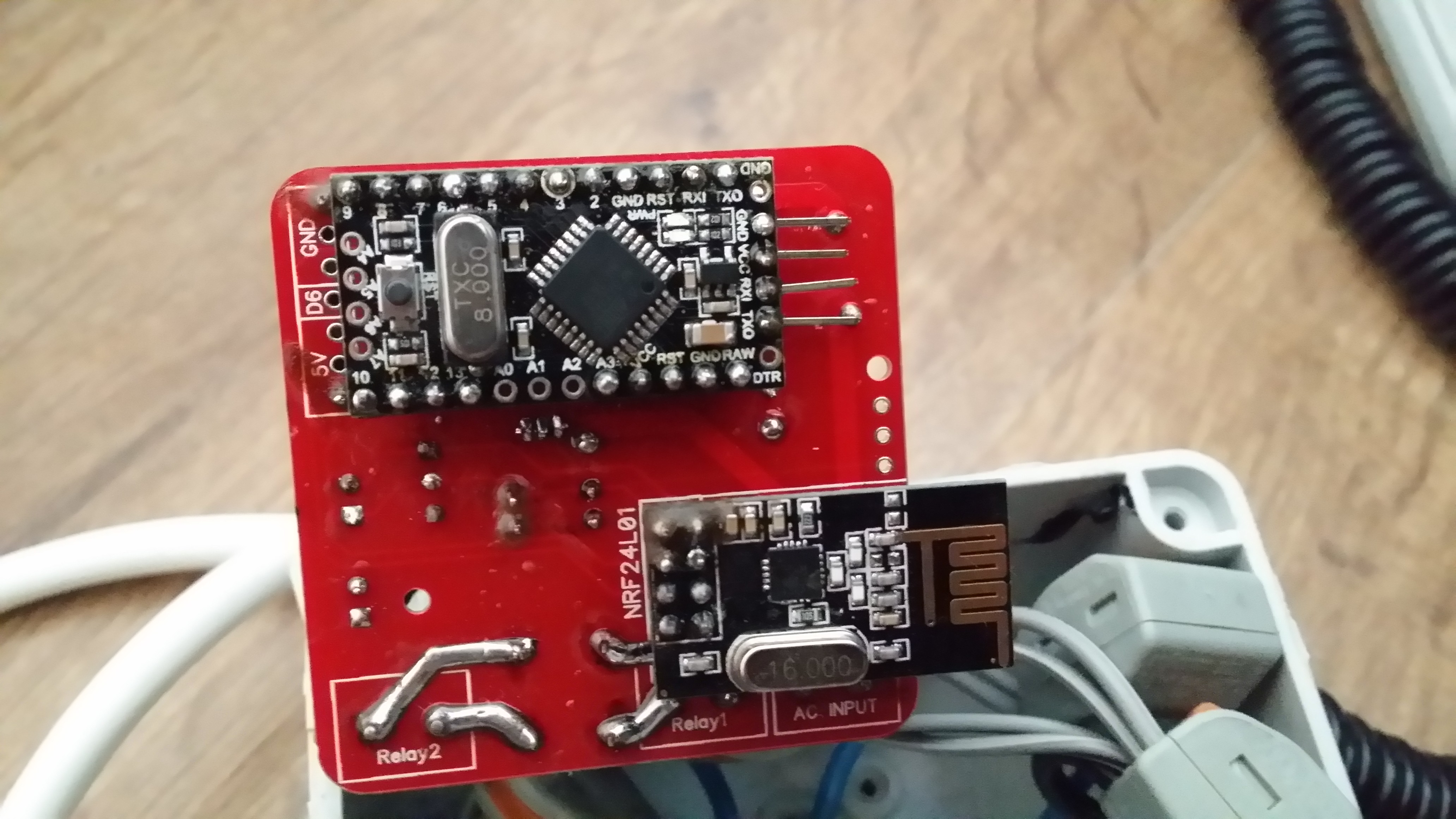
    That's where the biggest problem is on this board. I think the previous revision without the DS18 is safer, here there is less than 2mm creepage/clearance between main and low voltage traces and solder points, not enough 😞

    0_1478261384159_1478249033709-20161104_093851.jpg

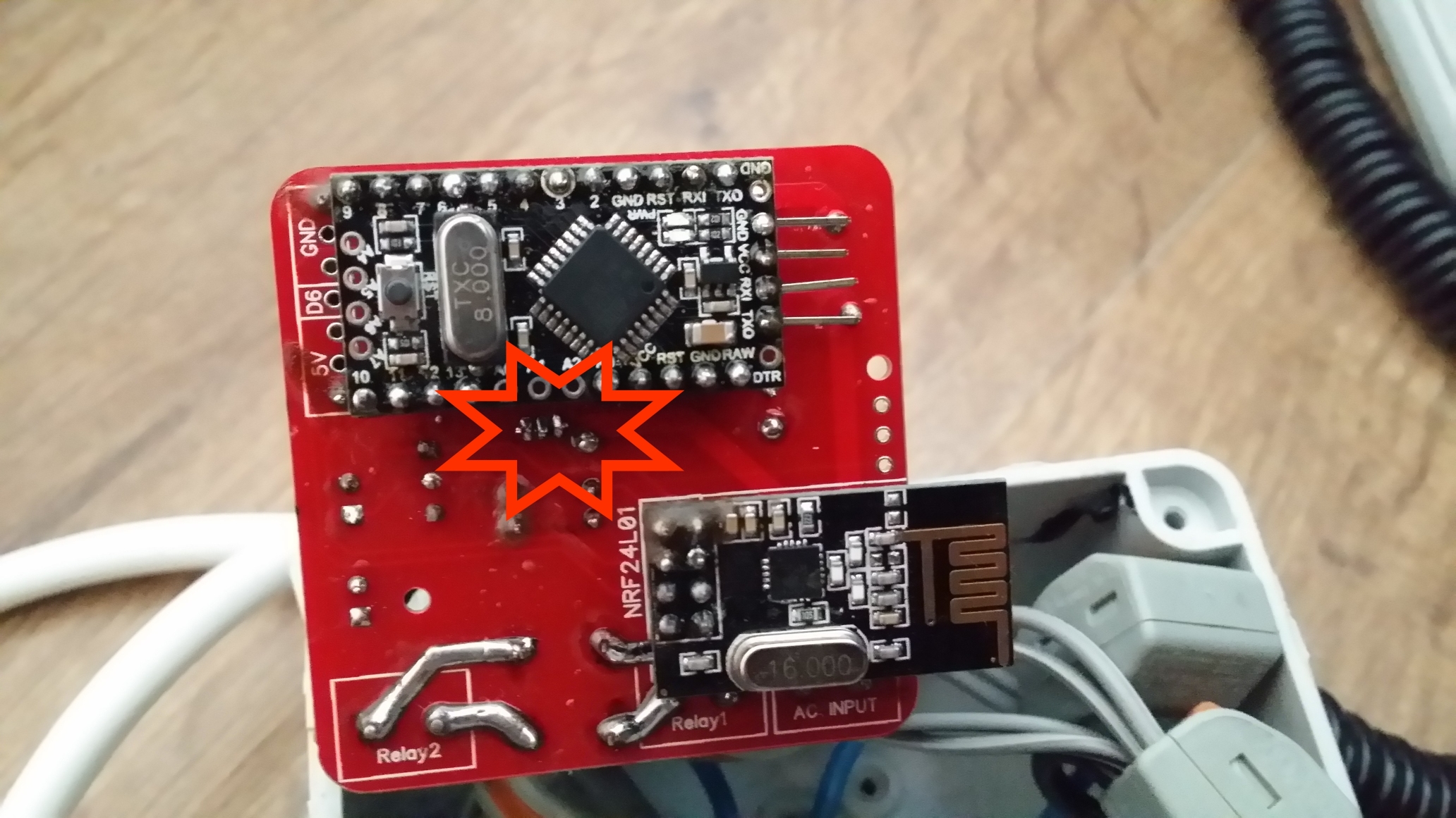
    There's also problem of mixing both main/low voltage everywhere in the board like near the NRF24.


  • Hi
    Noob questions sorry !
    1/ Can i used it with 3way switches ?
    2/ what are the pins 7 GND and 4 for ?
    Thinks


  • @ludoarchi

    @ludoarchi said:

    2/ what are the pins 7 GND and 4 for ?

    7 and 4 pins are mapped to 7 and 4 in/out of an arduino module. GND is for ground. These pins could be used to manually control relay state.


  • @mr_const ok i understand ! Thinks


  • hi, great project. I have one idea, is it possible to add current and voltage measurement ?


  • Ordered all the components for this project but now i see there are 12 v solid state relays on the list?? mine is not working, does it not need to have 5V version??


  • Hello,
    one question to the SSR Relay. The Arduino works with 5V, the SSR in the BOM is a 12V type. Is this a mistake? According to the Datasheet of the relay, the 12V type has an operating range from 9,6v to 14,4V


  • @Achim looks like a mistake in BOM (maybe that aliexpress listing has changed). Project uses same relay, but 5V version is needed.


  • Hardware Contributor

    Hello all,

    I have finished to assemble one of this board today.

    You can see some pictures of my board here :
    http://www.photorapide.com/albums/jordan/khreln/ac-dc-double-solid-state-relay-module.html

    If you want more pictures, ask me 😉

    The skecth works fine.

    Thx for this project.


  • @tonnerre33
    Avesome photogallery 😄
    whose sketch you used? because I have a problem with phisycal switches if I use sketch of Nca78 (I wrote about this earlier)


  • Hardware Contributor

    I used the sketch of Nca78 (2 months ago) but i only command relays from jeedom.
    I didn't test physical switch change because i don't have neutral wire in my switch box 😞


  • Hardware Contributor

    @okos said:

    @tonnerre33
    Avesome photogallery 😄
    whose sketch you used? because I have a problem with phisycal switches if I use sketch of Nca78 (I wrote about this earlier)

    Sorry Okos I didn't notice the problem came from my sketch. I'm not using the physical switches at the moment (same reason than tonnerre33, no neutral wire where I have put it at the moment), but I will try to find some time next week to fix the sketch. I'll fix the temperature sending too as sometimes I have some tiny variations of temperature that generate a lot of message sending in a burst and it perturbates other sensors.


  • @tonnerre33
    Just a quick question before i order the PCB, is it realy 4.6x5 cm? (thats what it says on the dirtypcb website, but when i mesure the PCB in the diptrace file, it shows a perfect 5x5 cm.
    can you please explain?


  • Hardware Contributor

    PCB is 5*5cm.
    You will also have to include the antenna of the NRF24 that is outside the PCB area.


  • Hardware Contributor

    Yes, it's 5x5cm.
    For information, i can't place this pcb in my wall box.
    I'll search other wall box this week in order to find a greater box..

    If someone want just to test the PCB i can sell one PCB if you are in france 😉
    I have ordered 10 boards but i don't think use everything.


  • Hardware Contributor

    @tonnerre33 said:

    If someone want just to test the PCB i can sell one PCB if you are in france 😉
    I have ordered 10 boards but i don't think use everything.

    Same here if you are in Vietnam or asia, just pay postage and I can send you 😛
    I have 20 as first order from Seeed took too long to arrive I thought it was lost, so I ordered again from PCBWay. Then received both orders.

    @tonnerre33 what is the space available in your wall box ? Would a 43*45mm pcb fit ? Only one relay/switch on my future board but phase + neutral in and phase + neutral out so no need to have additionnal connectors. No SMD, safe distance between tracks + milling. And 0.1'' tracks for load so it should be ok without reinforcing the tracks with solder.


  • @tonnerre33 Thanks buddy,
    do you know if dirtypcb are still operational? because i've seen in their website that they want to migrate to another website "dangerousprototype"
    did anyone order from them lately?


  • Hardware Contributor

    @br0wn dev.dangerousprototypes.com is supposed to be a test site only, dirtypcb is still functional.


  • @Nca78

    Merci ^^


  • Hardware Contributor

    @Nca78
    I have searched others wall box today but nothing fit (box from france).
    A 43x45mm pcb will fit well.
    I tried the pcb of the roller-shutter-node (45x46mm) and the wall box fits well.
    What do you mean by "no additionnal connectors" ? Will can use physical switches ?


  • @mr_const said:

    ybe that aliexpress listing has changed). Project uses same relay, but 5V version

    Uggh, I just received 20 of the 12v ones yesterday that I purchased from the BOM link. Is it safe to say that these will absolutely not work, or is there some way to adapt them with a step-up converter or something?


  • Hardware Contributor

    @tonnerre33 said:

    @Nca78
    I have searched others wall box today but nothing fit (box from france).
    A 43x45mm pcb will fit well.
    I tried the pcb of the roller-shutter-node (45x46mm) and the wall box fits well.
    What do you mean by "no additionnal connectors" ? Will can use physical switches ?

    I mean that with my future PCB you have neutral and phase in, and neutral and phase out. No need to have an extra wire from "phase in" to go to the input of the relay + a connector to connect "neutral" in to "neutral out" (that is not available on the board). At the moment with the board I installed, I have to use a wago connector for neutral which takes some extra space.


  • @Nca78 , would this module work as a roller shutter if the motor is not drawing more than 2A (the maximum current that this SSR relay can withstand is 2A) ?


  • Hardware Contributor

    Hello,

    Nca78 has already answered :

    @Nca78 said:

    @tonnerre33 said:

    Hi,

    can we install this module in a wall ?
    Can we command shutters ?

    For the wall, that's the idea of keeping the 50*50mm size 🙂
    For the shutters technically yes, but there are (at least) 2 problems :

    • if you have the 2 relays on at the same time = 2 directions you will probably kill the motor, there is no hardware protection on this board to avoid that (one of the relays must have power only when the other one is in off state). This can be done in software so it's not blocking.
    • if you want to be able to control the level/percentage of closing, you need to measure time from min to max position, to do that you need to measure current (when motor stop consuming current it means shutter has reached it's 0% or 100% position). But there is no current sensor on this board, so you either need to implement a manual calibration process (that will lose precision over time) or use only manual control.

    I am planning to test it when I have some time, and when I receive the PCB.


  • Looking to do something similar, Thanks for the contribution.
    However, I'd be very concerned about using an SSR (solid state relay) vs a mechanical relay. Even in the "OFF" position there is typically a small potential/current leakage through an SSR. When using SSR nearly all applications use a secondary mechanical disconnect to truely isolate the load, for service etc. Thoughts?


  • Hardware Contributor

    @Y_sam said:
    ... to truely isolate the load, for service etc. Thoughts?

    For that, disconnect the fuse in your fuse box, it's the only safe way.


  • @Y_sam,
    Nca78 highlighetd two problems:

    • The absence of mecanical interlock between the "up" and "down" relays, (you can use a soft interlock to prevent them from beign activated at the same time)
    • The absence of a current sensor to know whether or not the shutter is fully open or fully closed : I am trying to add an ACS712, but in my case, i will know if its fully open/close if the current becomes relatively high, because the my roller shutter doesnt have limit switches and keeps running ...

  • Hardware Contributor

    @JonnyDev13 said:

    @mr_const said:

    ybe that aliexpress listing has changed). Project uses same relay, but 5V version

    Uggh, I just received 20 of the 12v ones yesterday that I purchased from the BOM link. Is it safe to say that these will absolutely not work, or is there some way to adapt them with a step-up converter or something?

    You cannot adapt them with a step-up converter, there's no space on the PCB for that. But you should test them with 5V, if you are lucky they might work. I'm using 5V relays with 3.3V without any problem. The "must switch off" value in datasheet (for the original, remember what you bought is a clone...) is 0.9V which should be ok (real switch off value will probably be closer to this than to 5V) but the "must switch on" value is 8.4V which is quite far away from the 5V. The only way you will know if it will reliably switch one with 5V is to give it a try.

    @okos said:

    Hello.
    I tried to upload my two boards ( arduino pro mini 8Mhz , 3,3 V ) modified sketches but returned to sketch Nca78 (with DS18B20), unfortunately, does not operate a physical switch. Sometimes phisical switch changes state in domoticz ( not every time ) but relays do not change state.
    Switching on and switching off the lights of domoticz changes state relay without a problem.
    What could be wrong ?

    Sorry I'm a bit short on free time at the moment, didn't have time to take a look at the sketch yet.
    What you are saying is sometimes you change the physical switch position, it changes the status in domoticz, but the light status is not matching the status of the physical switch and the value of the switch in Domoticz ?

    For example: light is off and domoticz says off. Then you push the switch and domoticz says the light is on. But in fact the light is still off ?


  • @tonnerre33, je suis également en France et je n'ai pas de neutre dans mes interrupteurs. Peux tu me dire comment tu as pu tester le pcb stp. Mon anglais est loin d être top desolé !!


  • @Nca78 Thanks for your thoughts. I will try testing it with 5v and see what happens.


  • Hardware Contributor

    @laster13 hi, i have tried this pcb with my bedroom lamp. Indeed, these lamps are powered by electrical socket which include neutral wire.
    For the others lamps, i need to find how to command them without neutral wire 😉
    I am looking at this project but this is an smd project :

    https://www.openhardware.io/view/249/MDMSNode-Lighting

    @laster13 salut, en fait mes lampes de chambres sont sur prises commandées (donc accès au neutre), du coup j'utilise ce module pour ces lampes mais pour les autres bin il va falloir que je trouve autre chose 😉
    Je regarde un peu du coté de ce projet mais c'est du cms : voir le lien au dessus


  • Admin

    @laster13

    English please...


  • I Will tried to speak english 😗.
    Thanks tonnerre33 for your help. Could you give me à shema of your installation in the bedroom ?


  • Hardware Contributor


  • thanks, I'll try. You say that your lamps are powered by electrical socket .
    Is mounting possible on simple sockets with neutral wire? (non commandées)?


  • Hardware Contributor

    Sure you can use an electrical socket without switch control.
    But caution, max current is 2A ! It is ok for lamps but you can't supply a receiver which consumes more than 460VA per relay ( = 460W for resistive receiver).
    I didn't see protection for relays, be careful 😉


  • I am trying to test a montage which I am not sure about and besides when I plug the pcb on the socket the lamp remains on. I invite you to read my post on the Domoticz forum.
    http://easydomoticz.com/forum/viewtopic.php?f=20&t=2680&p=25219#p25219

    I am sorry for my english, I use the traducer of google


  • Hi All,

    This is my first post on this site!!

    Yes this is a really good project but for the UK controlling a light inside of a wall switch you would need to do the following.

    Re-wire the ceiling rose as in the UK there is a live feed from the rose that is switched by the switch and then returns to the rose to the "switched live" See http://www.diydoctor.org.uk/project_images/lights_and_switches/ceilingroseb2.jpg

    Put an extra cable up to the ceiling rose with the return cable from the board that goes to the switched live and add an extra terminal in the ceiling rose to link the neutral to the other side of the lamp fitting.

    If the back box is metal, it would need to be changed to a plastic box , I wouldn't myself want to mount the board in an earthed metal box!!

    As other contributors have noted there isn't any fusing on the live and neutral feeds if the SSR were to fail short because of a short circuit in the lamp or ceiling rose then there could be a large current going through board that could potentially cause a fire, safety is always the first thought with any mains electrical circuit.

    I could see this board being used in a plastic box inline to a table lamp etc. but it would need a lot of work to re-wire your house if you intended to use it behind a wall switch.


  • Hardware Contributor

    @laster13 Yes your schema is correct.
    The sketch has been modified by Nca78, you can try it first.
    The problem does not come from the unused switch, because i use this node without switch.


  • I'm going to do these for my light switches but what should I use for in wall on off switch without relay?


  • The link to to DirtyPCBs is broken, got a new one?


  • Hardware Contributor

    @Hilltan Hello, i think this link will be ok : http://dirtypcbs.com/store/details/885/mysensors-v3-3-2-light-switch

    For information, a few members have too many PCB of this node that's why if you are living in Vietnam or asia, Nca78 can send you PCB and if you are in france, i can send too (contact by pm for terms).

    I use this node since 20 days ago, and it's working well 😉


Suggested Topics

  • 23
  • 17
  • 17
  • 1
  • 10
  • 14
  • 14

0
Online

11.2k
Users

11.1k
Topics

112.5k
Posts