💬 Battery Powered Sensors
-
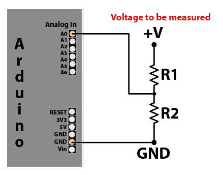
@bjacobt https://www.mysensors.org/build/battery#measuring-and-reporting-battery-level describes how the battery voltage is calculated and the example sketch has code for doing the calculation. Looks like you've missed reading this part:
// 1M, 470K divider across battery and using internal ADC ref of 1.1V // Sense point is bypassed with 0.1 uF cap to reduce noise at that point // ((1e6+470e3)/470e3)*1.1 = Vmax = 3.44 Volts // 3.44/1023 = Volts per bit = 0.003363075 ... float batteryV = sensorValue * 0.003363075; -
hi @mfalkvidd,
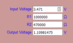
Do you mind clarifying a bit, I've done sensorValue * 0.003363075
analogRead(BATTERY_SENSE_PIN);Gives me 330, so
330 * 0.003363075 = 1.10981475 voltsThank You!
Jacob -
analogRead(BATTERY_SENSE_PIN);must give you 1023 and not 330.
For me it's a problem of value resistance or analogReference.Try to add this
analogReference(INTERNAL);
sensorValue = analogRead(BATTERY_SENSE_PIN);
  #ifdef MY_DEBUG
 Serial.print("Value A0 before force reference: ");
 Serial.print(sensorValue);
#endif
delay(10000);
sensorValue = analogRead(BATTERY_SENSE_PIN);
  #ifdef MY_DEBUG
 Serial.print("Value A0 after force reference: ");
 Serial.print(sensorValue);
#endif
Just after this existing code :
   #ifdef MY_DEBUG
   Serial.println(sensorValue);
   #endif
And plz send me the logs of the node ;)
-
analogRead(BATTERY_SENSE_PIN);must give you 1023 and not 330.
For me it's a problem of value resistance or analogReference.Try to add this
analogReference(INTERNAL);
sensorValue = analogRead(BATTERY_SENSE_PIN);
  #ifdef MY_DEBUG
 Serial.print("Value A0 before force reference: ");
 Serial.print(sensorValue);
#endif
delay(10000);
sensorValue = analogRead(BATTERY_SENSE_PIN);
  #ifdef MY_DEBUG
 Serial.print("Value A0 after force reference: ");
 Serial.print(sensorValue);
#endif
Just after this existing code :
   #ifdef MY_DEBUG
   Serial.println(sensorValue);
   #endif
And plz send me the logs of the node ;)
@tonnerre33 Its still the same
Starting sensor (RNNNA-, 2.0.0)
TSM:INIT
TSM:RADIO:OK
TSP:ASSIGNID:OK (ID=101)
TSM:FPAR
TSP:MSG:SEND 101-101-255-255 s=255,c=3,t=7,pt=0,l=0,sg=0,ft=0,st=bc:
TSP:MSG:READ 0-0-101 s=255,c=3,t=8,pt=1,l=1,sg=0:0
TSP:MSG:FPAR RES (ID=0, dist=0)
TSP:MSG:PAR OK (ID=0, dist=1)
TSM:FPAR:OK
TSM:ID
TSM:CHKID:OK (ID=101)
TSM:UPL
TSP:PING:SEND (dest=0)
TSP:MSG:SEND 101-101-0-0 s=255,c=3,t=24,pt=1,l=1,sg=0,ft=0,st=ok:1
TSP:MSG:READ 0-0-101 s=255,c=3,t=25,pt=1,l=1,sg=0:1
TSP:MSG:PONG RECV (hops=1)
TSP:CHKUPL:OK
TSM:UPL:OK
TSM:READY
TSP:MSG:SEND 101-101-0-0 s=255,c=3,t=15,pt=6,l=2,sg=0,ft=0,st=ok:0100
TSP:MSG:SEND 101-101-0-0 s=255,c=0,t=17,pt=0,l=5,sg=0,ft=0,st=ok:2.0.0
TSP:MSG:SEND 101-101-0-0 s=255,c=3,t=6,pt=1,l=1,sg=0,ft=0,st=ok:0
TSP:MSG:READ 0-0-101 s=255,c=3,t=15,pt=6,l=2,sg=0:0100
TSP:MSG:SEND 101-101-0-0 s=255,c=3,t=11,pt=0,l=13,sg=0,ft=0,st=ok:Battery Meter
TSP:MSG:SEND 101-101-0-0 s=255,c=3,t=12,pt=0,l=3,sg=0,ft=0,st=ok:1.0
Request registration...
TSP:MSG:SEND 101-101-0-0 s=255,c=3,t=26,pt=1,l=1,sg=0,ft=0,st=ok:2
TSP:MSG:READ 0-0-101 s=255,c=3,t=27,pt=1,l=1,sg=0:1
Node registration=1
Init complete, id=101, parent=0, distance=1, registration=1
330
Value A0 before force reference: 327
Value A0 after force reference: 329
Battery Voltage: 1.11 V
Battery percent: 32 %
TSP:MSG:SEND 101-101-0-0 s=255,c=3,t=0,pt=1,l=1,sg=0,ft=0,st=ok:32/** * The MySensors Arduino library handles the wireless radio link and protocol * between your home built sensors/actuators and HA controller of choice. * The sensors forms a self healing radio network with optional repeaters. Each * repeater and gateway builds a routing tables in EEPROM which keeps track of the * network topology allowing messages to be routed to nodes. * * Created by Henrik Ekblad <henrik.ekblad@mysensors.org> * Copyright (C) 2013-2015 Sensnology AB * Full contributor list: https://github.com/mysensors/Arduino/graphs/contributors * * Documentation: http://www.mysensors.org * Support Forum: http://forum.mysensors.org * * This program is free software; you can redistribute it and/or * modify it under the terms of the GNU General Public License * version 2 as published by the Free Software Foundation. * ******************************* * * DESCRIPTION * * This is an example that demonstrates how to report the battery level for a sensor * Instructions for measuring battery capacity on A0 are available here: * http://www.mysensors.org/build/battery * */ #define MY_NODE_ID 101 // Enable debug prints to serial monitor #define MY_DEBUG // Enable and select radio type attached #define MY_RADIO_NRF24 //#define MY_RADIO_RFM69 #include <MySensors.h> int BATTERY_SENSE_PIN = A0; // select the input pin for the battery sense point unsigned long SLEEP_TIME = 100000; // sleep time between reads (seconds * 1000 milliseconds) int oldBatteryPcnt = 0; void setup() { // use the 1.1 V internal reference #if defined(__AVR_ATmega2560__) analogReference(INTERNAL1V1); #else analogReference(INTERNAL); #endif } void presentation() { // Send the sketch version information to the gateway and Controller sendSketchInfo("Battery Meter", "1.0"); } void loop() { // get the battery Voltage int sensorValue = analogRead(BATTERY_SENSE_PIN); #ifdef MY_DEBUG Serial.println(sensorValue); #endif analogReference(INTERNAL); sensorValue = analogRead(BATTERY_SENSE_PIN); #ifdef MY_DEBUG Serial.print("Value A0 before force reference: "); Serial.println(sensorValue); #endif delay(10000); sensorValue = analogRead(BATTERY_SENSE_PIN); #ifdef MY_DEBUG Serial.print("Value A0 after force reference: "); Serial.println(sensorValue); #endif // 1M, 470K divider across battery and using internal ADC ref of 1.1V // Sense point is bypassed with 0.1 uF cap to reduce noise at that point // ((1e6+470e3)/470e3)*1.1 = Vmax = 3.44 Volts // 3.44/1023 = Volts per bit = 0.003363075 int batteryPcnt = sensorValue / 10; #ifdef MY_DEBUG float batteryV = sensorValue * 0.003363075; Serial.print("Battery Voltage: "); Serial.print(batteryV); Serial.println(" V"); Serial.print("Battery percent: "); Serial.print(batteryPcnt); Serial.println(" %"); #endif if (oldBatteryPcnt != batteryPcnt) { // Power up radio after sleep sendBatteryLevel(batteryPcnt); oldBatteryPcnt = batteryPcnt; } sleep(SLEEP_TIME); }``` -
Ok it's not a problem with the analogReference, you can delete this part of code.
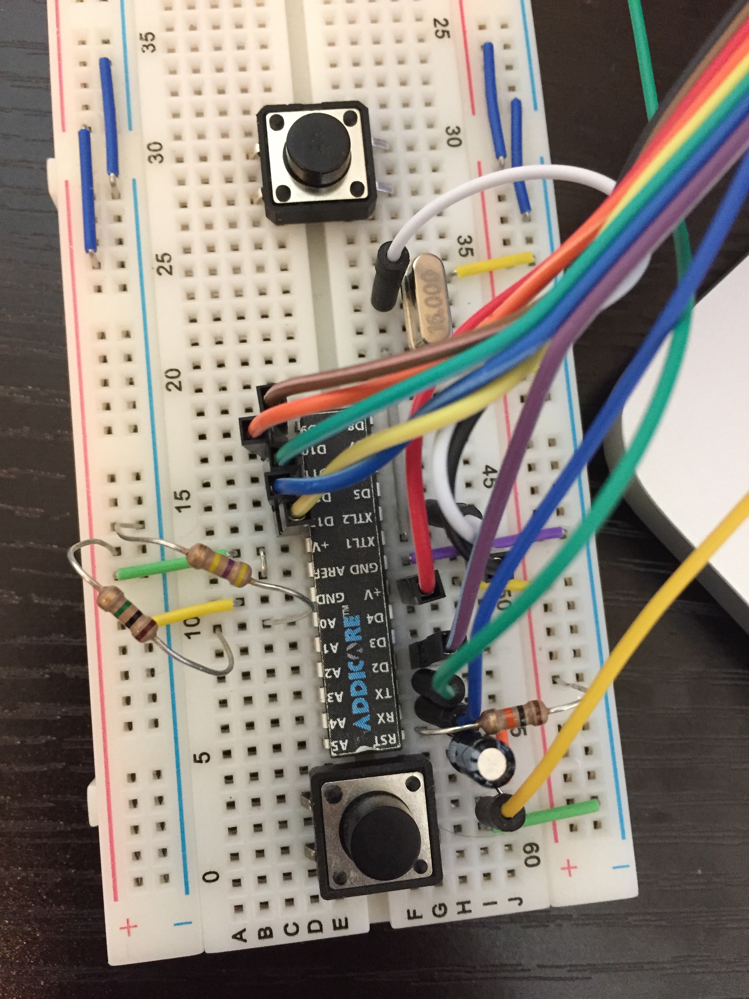
Did you control your resistance value and did you do this schema ?
-
Ok try to remove the jumper between V+ and AREF
-
Ok try to remove the jumper between V+ and AREF
@tonnerre33 That was it!
I'm getting Battery Voltage: 3.10 V
Battery percent: 92 %Thank you so much :)
Starting sensor (RNNNA-, 2.0.0)
TSM:INIT
TSM:RADIO:OK
TSP:ASSIGNID:OK (ID=101)
TSM:FPAR
TSP:MSG:SEND 101-101-255-255 s=255,c=3,t=7,pt=0,l=0,sg=0,ft=0,st=bc:
TSP:MSG:READ 0-0-101 s=255,c=3,t=8,pt=1,l=1,sg=0:0
TSP:MSG:FPAR RES (ID=0, dist=0)
TSP:MSG:PAR OK (ID=0, dist=1)
TSM:FPAR:OK
TSM:ID
TSM:CHKID:OK (ID=101)
TSM:UPL
TSP:PING:SEND (dest=0)
TSP:MSG:SEND 101-101-0-0 s=255,c=3,t=24,pt=1,l=1,sg=0,ft=0,st=ok:1
TSP:MSG:READ 0-0-101 s=255,c=3,t=25,pt=1,l=1,sg=0:1
TSP:MSG:PONG RECV (hops=1)
TSP:CHKUPL:OK
TSM:UPL:OK
TSM:READY
TSP:MSG:SEND 101-101-0-0 s=255,c=3,t=15,pt=6,l=2,sg=0,ft=0,st=ok:0100
!TSP:MSG:SEND 101-101-0-0 s=255,c=0,t=17,pt=0,l=5,sg=0,ft=0,st=fail:2.0.0
TSP:MSG:SEND 101-101-0-0 s=255,c=3,t=6,pt=1,l=1,sg=0,ft=1,st=ok:0
TSP:MSG:SEND 101-101-0-0 s=255,c=3,t=11,pt=0,l=13,sg=0,ft=0,st=ok:Battery Meter
TSP:MSG:SEND 101-101-0-0 s=255,c=3,t=12,pt=0,l=3,sg=0,ft=0,st=ok:1.0
Request registration...
TSP:MSG:SEND 101-101-0-0 s=255,c=3,t=26,pt=1,l=1,sg=0,ft=0,st=ok:2
TSP:MSG:READ 0-0-101 s=255,c=3,t=27,pt=1,l=1,sg=0:1
Node registration=1
Init complete, id=101, parent=0, distance=1, registration=1
922
Value A0 before force reference: 924
Value A0 after force reference: 923
Battery Voltage: 3.10 V
Battery percent: 92 %
TSP:MSG:SEND 101-101-0-0 s=255,c=3,t=0,pt=1,l=1,sg=0,ft=0,st=ok:92 -
can Li 18650 3.7 batteries be used as they are rechargeable ? knowing the max voltage at full might reach 4.1-4.2v ? maybe keeping the voltage regulator ?
@Meshx86 yes they can be used but as you've already identified the nrf (and maybe other components) will need to be protected from the high voltage when the battery is full.
The self-discharge rate of li-ion is higher than alkaline batteries which might affect how long the node can run before it needs charging.
-
Hi,
I just built the circuit which is explained in the thread with a Pro Mini 3.3 8 mHz
So far so good, I can read the voltage of the battery etc but my problem is, it consumes about 1.2 mA while in sleep, this is about factor 10 of the findings from the thread.
I just copied the code 1:1
Any glue what could be wrong or what get others with that setup? The Arduino is not modified at all.Thanks
SJ -
Hi,
I just built the circuit which is explained in the thread with a Pro Mini 3.3 8 mHz
So far so good, I can read the voltage of the battery etc but my problem is, it consumes about 1.2 mA while in sleep, this is about factor 10 of the findings from the thread.
I just copied the code 1:1
Any glue what could be wrong or what get others with that setup? The Arduino is not modified at all.Thanks
SJ@parachutesj you have to modify the pro mini. Remove the power led according to instructions!
-
@parachutesj you have to modify the pro mini. Remove the power led according to instructions!
@Nicklas-Starkel thank you. If one could read...
I read the description again and thought that it should be 120uA stock and when removing LED and regulator it will even go down further but thinking about it, how should at base 120 uA and removing LED save additional 1.5mA???? LOL, sorry was a long day.My Fluke reads 0.044 mA in sleep now (without LED). Sweet!
-
Another battery related question that I really do not understand.
Are there different versions on how to read battery consumption?I see some sketches uses:
long readVcc() {
  long result;
  // Read 1.1V reference against AVcc
  ADMUX = _BV(REFS0) | _BV(MUX3) | _BV(MUX2) | _BV(MUX1);
  delay(2); // Wait for Vref to settle
  noInterrupts ();
  // start the conversion
  ADCSRA |= _BV (ADSC) | _BV (ADIE);
  set_sleep_mode (SLEEP_MODE_ADC);    // sleep during sample
  interrupts ();
  sleep_mode ();
  // reading should be done, but better make sure
  // maybe the timer interrupt fired
  while (bit_is_set(ADCSRA,ADSC));
  result = ADCL;
  result |= ADCH<<8;
  result = 1126400L / result; // Back-calculate AVcc in mV```
However some (like the original one in this thread) uses:
int sensorValue = analogRead(BATTERY_SENSE_PIN);Is it due to different libraries or maybe it is the same but just programming wise different?
-
If you are using the first sketch you dont have to use a seperate pin to measure the input voltage. There are also no resistors.
You can run this on a bare ATmega with minimal hardware.
@gloob thanks!
One would think running with no resistors and not using a separate PIN would be better.@hek or @mfalkvidd , any comments as to why the original sketch is preferred over the other 'way' in this article?
-
@gloob thanks!
One would think running with no resistors and not using a separate PIN would be better.@hek or @mfalkvidd , any comments as to why the original sketch is preferred over the other 'way' in this article?
-
@hek , I've read that post several times :)
Since it was so outdated (2 years) I naturally assumed the 'battery powering article' was a newer way to do it (especially since mys2.0).
Also, the post you linked to is attributed if you use no voltage regulator.
And in the article this is also one of the things you are recommended to remove, hence making it even more confusing as to why the article describes another way than the post. -
i just want to get this once and for all, so others coming by gets it directly instead of going through all the 2 threads posts, please correct me if i am wrong:
1- using the voltage divider is needed if there is a voltage regulator / booster where where VBatt != Vcc.
2- using the voltage regulator is not needed if the voltage regulator is removed / no booster is used (powering directly from 2 x AA batteries) where VBatt == Vcc.*I've noticed the 2nd method requires inputting battrie's DMM measured values vs arduino ones for correction, is this a down side if you need to change the battery later on ? or is it just programmed once ? and does the 1st method rquirs these corrections too ?
Cheers
-
i just want to get this once and for all, so others coming by gets it directly instead of going through all the 2 threads posts, please correct me if i am wrong:
1- using the voltage divider is needed if there is a voltage regulator / booster where where VBatt != Vcc.
2- using the voltage regulator is not needed if the voltage regulator is removed / no booster is used (powering directly from 2 x AA batteries) where VBatt == Vcc.*I've noticed the 2nd method requires inputting battrie's DMM measured values vs arduino ones for correction, is this a down side if you need to change the battery later on ? or is it just programmed once ? and does the 1st method rquirs these corrections too ?
Cheers
@Meshx86
actually, you need a voltage divider if the voltage to be measured is above the maximum allowed by the processor at the speed you are running it.If Vcc is 5V, then any voltage above 5V should be measured via a voltage divider.
If Vcc is 3.3V same principle, but you could get away with measuring 5V directly (would not kill the processor), but your values may be off.
 ,
,