Skip to content
  • MySensors
  • OpenHardware.io
  • Categories
  • Recent
  • Tags
  • Popular
Skins
  • Light
  • Brite
  • Cerulean
  • Cosmo
  • Flatly
  • Journal
  • Litera
  • Lumen
  • Lux
  • Materia
  • Minty
  • Morph
  • Pulse
  • Sandstone
  • Simplex
  • Sketchy
  • Spacelab
  • United
  • Yeti
  • Zephyr
  • Dark
  • Cyborg
  • Darkly
  • Quartz
  • Slate
  • Solar
  • Superhero
  • Vapor

  • Default (No Skin)
  • No Skin
Collapse
Brand Logo
  1. Home
  2. Troubleshooting
  3. Arduino UNO ethernet gateway problem

Arduino UNO ethernet gateway problem

Scheduled Pinned Locked Moved Troubleshooting
20 Posts 4 Posters 7.8k Views 4 Watching
  • Oldest to Newest
  • Newest to Oldest
  • Most Votes
Reply
  • Reply as topic
Log in to reply
This topic has been deleted. Only users with topic management privileges can see it.
  • M Offline
    M Offline
    Misna
    wrote on last edited by
    #1

    Hi!

    I'm just starting my Mysensors journey with building an ethernet gateway based on Arduino UNO.

    Parts I'm using:

    • Arduino UNO from somewhere on Aliexpress (link does not work anymore)
    • UNO ethernet shield from here: https://www.aliexpress.com/item/UNO-Shield-Ethernet-Shield-W5100-R3-Development-board-FOR-arduino/32341820750.html?spm=2114.13010608.0.0.lpQQAC
    • NRF24L-module from here: https://www.aliexpress.com/item/1sets-Special-promotions-1100-meter-long-distance-NRF24L01-PA-LNA-wireless-modules-with-antenna/32341792715.html?spm=2114.13010608.0.0.lpQQAC

    I connected the RF-module how described here: https://www.mysensors.org/build/ethernet_gateway
    A2 - MISO
    A1 - MOSI
    A0 - SCK
    6 - SCN
    5 - CE

    0_1490345800093_IMG_7921.JPG

    I uploaded the W5100 Gateway scetch and the device seems to be in a endless boot loop.

    Here's what I see in the serial monitor of Arduino IDE:

    0;255;3;0;9;MCO:BGN:INIT GW,CP=RNNGA--,VER=2.1.1
    0;255;3;0;9;TSM:INIT
    0;255;3;0;9;TSF:WUR:MS=0
    0;255;3;0;9;!TSM:INIT:TSP FAIL
    0;255;3;0;9;TSM:FAIL:CNT=1
    0;255;3;0;9;TSM:FAIL:PDT
    0;255;3;0;9;TSM:FAIL:RE-INIT
    0;255;3;0;9;TSM:INIT
    0;255;3;0;9;!TSM:INIT:TSP FAIL
    0;255;3;0;9;TSM:FAIL:CNT=2
    0;255;3;0;9;TSM:FAIL:PDT
    0;255;3;0;9;TSM:FAIL:RE-INIT
    0;255;3;0;9;TSM:INIT
    0;255;3;0;9;!TSM:INIT:TSP FAIL
    0;255;3;0;9;TSM:FAIL:CNT=3
    0;255;3;0;9;TSM:FAIL:PDT
    

    And here is the scetch:

    // Enable debug prints to serial monitor
    #define MY_DEBUG
    
    // Enable and select radio type attached
    #define MY_RADIO_NRF24
    //#define MY_RADIO_RFM69
    
    // Enable gateway ethernet module type
    #define MY_GATEWAY_W5100
    
    // W5100 Ethernet module SPI enable (optional if using a shield/module that manages SPI_EN signal)
    #define MY_W5100_SPI_EN 4
    
    // Enable Soft SPI for NRF radio (note different radio wiring is required)
    // The W5100 ethernet module seems to have a hard time co-operate with
    // radio on the same spi bus.
    #if !defined(MY_W5100_SPI_EN) && !defined(ARDUINO_ARCH_SAMD)
    #define MY_SOFTSPI
    #define MY_SOFT_SPI_SCK_PIN 14
    #define MY_SOFT_SPI_MISO_PIN 16
    #define MY_SOFT_SPI_MOSI_PIN 15
    #endif
    
    // When W5100 is connected we have to move CE/CSN pins for NRF radio
    #ifndef MY_RF24_CE_PIN
    #define MY_RF24_CE_PIN 5
    #endif
    #ifndef MY_RF24_CS_PIN
    #define MY_RF24_CS_PIN 6
    #endif
    
    // Enable to UDP
    //#define MY_USE_UDP
    
    //#define MY_IP_ADDRESS 192,168,178,66   // If this is disabled, DHCP is used to retrieve address
    // Renewal period if using DHCP
    #define MY_IP_RENEWAL_INTERVAL 60000
    // The port to keep open on node server mode / or port to contact in client mode
    #define MY_PORT 5003
    
    // Controller ip address. Enables client mode (default is "server" mode).
    // Also enable this if MY_USE_UDP is used and you want sensor data sent somewhere.
    //#define MY_CONTROLLER_IP_ADDRESS 192, 168, 178, 254
    
    // The MAC address can be anything you want but should be unique on your network.
    // Newer boards have a MAC address printed on the underside of the PCB, which you can (optionally) use.
    // Note that most of the Ardunio examples use  "DEAD BEEF FEED" for the MAC address.
    #define MY_MAC_ADDRESS 0xDE, 0xAD, 0xBE, 0xEF, 0xFE, 0xED
    
    // Enable inclusion mode
    #define MY_INCLUSION_MODE_FEATURE
    // Enable Inclusion mode button on gateway
    //#define MY_INCLUSION_BUTTON_FEATURE
    // Set inclusion mode duration (in seconds)
    #define MY_INCLUSION_MODE_DURATION 60
    // Digital pin used for inclusion mode button
    //#define MY_INCLUSION_MODE_BUTTON_PIN  3
    
    // Set blinking period
    #define MY_DEFAULT_LED_BLINK_PERIOD 300
    
    // Flash leds on rx/tx/err
    // Uncomment to override default HW configurations
    //#define MY_DEFAULT_ERR_LED_PIN 7  // Error led pin
    //#define MY_DEFAULT_RX_LED_PIN  8  // Receive led pin
    //#define MY_DEFAULT_TX_LED_PIN  9  // Transmit led pin
    
    
    #if defined(MY_USE_UDP)
    #include <EthernetUdp.h>
    #endif
    #include <Ethernet.h>
    #include <MySensors.h>
    
    
    void setup()
    {
    }
    
    void loop()
    {
    }
    
    Boots33B 1 Reply Last reply
    0
    • gohanG Offline
      gohanG Offline
      gohan
      Mod
      wrote on last edited by
      #2

      I don't see any capacitor on vcc of radio module.

      1 Reply Last reply
      0
      • M Offline
        M Offline
        Misna
        wrote on last edited by
        #3

        Hi!

        That is true. I thought that it was optional as described here. If you experience bad reception or if transmitted data never reaches destination, try adding a decoupling capacitor

        I can try adding a capasitor when I get home.

        1 Reply Last reply
        0
        • gohanG Offline
          gohanG Offline
          gohan
          Mod
          wrote on last edited by
          #4

          Well... it depends on the source of the 3.3v, but looking at your picture you are taking power directly from arduino and that is for sure not able to supply enough power for a PA radio. Try also to set nrf24 power to MIN and start from there. If I were you I would use an adapter with voltage regulator from 5v to 3.3v that would make like easier. If you are going to add capacitor, put it as close as possible to radio module (you could solder on the other side of the pins.

          1 Reply Last reply
          0
          • M Misna

            Hi!

            I'm just starting my Mysensors journey with building an ethernet gateway based on Arduino UNO.

            Parts I'm using:

            • Arduino UNO from somewhere on Aliexpress (link does not work anymore)
            • UNO ethernet shield from here: https://www.aliexpress.com/item/UNO-Shield-Ethernet-Shield-W5100-R3-Development-board-FOR-arduino/32341820750.html?spm=2114.13010608.0.0.lpQQAC
            • NRF24L-module from here: https://www.aliexpress.com/item/1sets-Special-promotions-1100-meter-long-distance-NRF24L01-PA-LNA-wireless-modules-with-antenna/32341792715.html?spm=2114.13010608.0.0.lpQQAC

            I connected the RF-module how described here: https://www.mysensors.org/build/ethernet_gateway
            A2 - MISO
            A1 - MOSI
            A0 - SCK
            6 - SCN
            5 - CE

            0_1490345800093_IMG_7921.JPG

            I uploaded the W5100 Gateway scetch and the device seems to be in a endless boot loop.

            Here's what I see in the serial monitor of Arduino IDE:

            0;255;3;0;9;MCO:BGN:INIT GW,CP=RNNGA--,VER=2.1.1
            0;255;3;0;9;TSM:INIT
            0;255;3;0;9;TSF:WUR:MS=0
            0;255;3;0;9;!TSM:INIT:TSP FAIL
            0;255;3;0;9;TSM:FAIL:CNT=1
            0;255;3;0;9;TSM:FAIL:PDT
            0;255;3;0;9;TSM:FAIL:RE-INIT
            0;255;3;0;9;TSM:INIT
            0;255;3;0;9;!TSM:INIT:TSP FAIL
            0;255;3;0;9;TSM:FAIL:CNT=2
            0;255;3;0;9;TSM:FAIL:PDT
            0;255;3;0;9;TSM:FAIL:RE-INIT
            0;255;3;0;9;TSM:INIT
            0;255;3;0;9;!TSM:INIT:TSP FAIL
            0;255;3;0;9;TSM:FAIL:CNT=3
            0;255;3;0;9;TSM:FAIL:PDT
            

            And here is the scetch:

            // Enable debug prints to serial monitor
            #define MY_DEBUG
            
            // Enable and select radio type attached
            #define MY_RADIO_NRF24
            //#define MY_RADIO_RFM69
            
            // Enable gateway ethernet module type
            #define MY_GATEWAY_W5100
            
            // W5100 Ethernet module SPI enable (optional if using a shield/module that manages SPI_EN signal)
            #define MY_W5100_SPI_EN 4
            
            // Enable Soft SPI for NRF radio (note different radio wiring is required)
            // The W5100 ethernet module seems to have a hard time co-operate with
            // radio on the same spi bus.
            #if !defined(MY_W5100_SPI_EN) && !defined(ARDUINO_ARCH_SAMD)
            #define MY_SOFTSPI
            #define MY_SOFT_SPI_SCK_PIN 14
            #define MY_SOFT_SPI_MISO_PIN 16
            #define MY_SOFT_SPI_MOSI_PIN 15
            #endif
            
            // When W5100 is connected we have to move CE/CSN pins for NRF radio
            #ifndef MY_RF24_CE_PIN
            #define MY_RF24_CE_PIN 5
            #endif
            #ifndef MY_RF24_CS_PIN
            #define MY_RF24_CS_PIN 6
            #endif
            
            // Enable to UDP
            //#define MY_USE_UDP
            
            //#define MY_IP_ADDRESS 192,168,178,66   // If this is disabled, DHCP is used to retrieve address
            // Renewal period if using DHCP
            #define MY_IP_RENEWAL_INTERVAL 60000
            // The port to keep open on node server mode / or port to contact in client mode
            #define MY_PORT 5003
            
            // Controller ip address. Enables client mode (default is "server" mode).
            // Also enable this if MY_USE_UDP is used and you want sensor data sent somewhere.
            //#define MY_CONTROLLER_IP_ADDRESS 192, 168, 178, 254
            
            // The MAC address can be anything you want but should be unique on your network.
            // Newer boards have a MAC address printed on the underside of the PCB, which you can (optionally) use.
            // Note that most of the Ardunio examples use  "DEAD BEEF FEED" for the MAC address.
            #define MY_MAC_ADDRESS 0xDE, 0xAD, 0xBE, 0xEF, 0xFE, 0xED
            
            // Enable inclusion mode
            #define MY_INCLUSION_MODE_FEATURE
            // Enable Inclusion mode button on gateway
            //#define MY_INCLUSION_BUTTON_FEATURE
            // Set inclusion mode duration (in seconds)
            #define MY_INCLUSION_MODE_DURATION 60
            // Digital pin used for inclusion mode button
            //#define MY_INCLUSION_MODE_BUTTON_PIN  3
            
            // Set blinking period
            #define MY_DEFAULT_LED_BLINK_PERIOD 300
            
            // Flash leds on rx/tx/err
            // Uncomment to override default HW configurations
            //#define MY_DEFAULT_ERR_LED_PIN 7  // Error led pin
            //#define MY_DEFAULT_RX_LED_PIN  8  // Receive led pin
            //#define MY_DEFAULT_TX_LED_PIN  9  // Transmit led pin
            
            
            #if defined(MY_USE_UDP)
            #include <EthernetUdp.h>
            #endif
            #include <Ethernet.h>
            #include <MySensors.h>
            
            
            void setup()
            {
            }
            
            void loop()
            {
            }
            
            Boots33B Offline
            Boots33B Offline
            Boots33
            Hero Member
            wrote on last edited by
            #5

            @Misna You have un-commented the line

            #define MY_W5100_SPI_EN 4

            That will stop soft spi from being used. You should comment it back out. //#define MY_W5100_SPI_EN 4

            see this post for some more info and wiring hookup

            1 Reply Last reply
            0
            • M Offline
              M Offline
              Misna
              wrote on last edited by Misna
              #6

              Hi!

              I commented the line #define MY_W5100_SPI_EN 4 and wired the module as described in the post linked.
              I also added this line: #define MY_RF24_PA_LEVEL RF24_PA_MIN to lower the power need.

              Tried to add this adapter board: https://www.aliexpress.com/item/New-Socket-Adapter-plate-Board-for-8Pin-NRF24L01-Wireless-Transceive-module-51/32655936568.html?spm=2114.13010608.0.0.WnqXqC

              Now this is what I'm getting with DHCP configuration:

              0;255;3;0;9;MCO:BGN:INIT GW,CP=RNNGA--,VER=2.1.1
              0;255;3;0;9;TSM:INIT
              0;255;3;0;9;TSF:WUR:MS=0
              0;255;3;0;9;TSM:INIT:TSP OK
              0;255;3;0;9;TSM:INIT:GW MODE
              0;255;3;0;9;TSM:READY:ID=0,PAR=0,DIS=0
              0;255;3;0;9;MCO:REG:NOT NEEDED
              DHCP FAILURE...0;255;3;0;9;!MCO:BGN:TSP FAIL
              

              And with static IP:

              IP: 192.168.10.25
              0;255;3;0;9;MCO:BGN:STP
              0;255;3;0;9;MCO:BGN:INIT OK,TSP=1
              

              Btw my versions used:

              • macOS 10.12.3
              • Arduino IDE 1.8.2
              • Arduino AVR Boards 1.6.18
              • MySensors library 2.1.1

              Still the board is somehow looping and does not appear to the network.

              1 Reply Last reply
              0
              • gohanG Offline
                gohanG Offline
                gohan
                Mod
                wrote on last edited by
                #7

                Remember the capacitor.
                It's strange the ethernet is not getting the IP from DHCP

                1 Reply Last reply
                0
                • M Offline
                  M Offline
                  Misna
                  wrote on last edited by
                  #8

                  Yes it is and even the link lights wont light up on my switch. I'll try to add the capasitor tomorrow. I'll also try this with a regular radio module (without the antenna)

                  Boots33B 1 Reply Last reply
                  0
                  • gohanG Offline
                    gohanG Offline
                    gohan
                    Mod
                    wrote on last edited by
                    #9

                    I hope you don't have a faulty shield as I had that cost me many hours of debugging for nothing

                    1 Reply Last reply
                    0
                    • M Misna

                      Yes it is and even the link lights wont light up on my switch. I'll try to add the capasitor tomorrow. I'll also try this with a regular radio module (without the antenna)

                      Boots33B Offline
                      Boots33B Offline
                      Boots33
                      Hero Member
                      wrote on last edited by Boots33
                      #10

                      @Misna Don't know if this is still a problem but some time back there was an issue with certain versions of the Arduino IDE causing problems with the w5100 gateway.
                      You may need to roll back the IDE or board definitions and see if that fixes the problem. Have a look Here for a bit more info.

                      1 Reply Last reply
                      0
                      • A Offline
                        A Offline
                        ArduiSens
                        wrote on last edited by
                        #11

                        Hello,
                        You will solve the problem when compiling your arduino sketch with IDE 1.6.8.
                        I have compiled my UNO with ethernet shield at top 2 minutes ago and now I have full contact with Domotics (on Synology NAS).
                        go for it!

                        MySensors 2.3.2; contr:Domoticz; layer: RS485, nRF24; gw: Ethernet, Serial

                        1 Reply Last reply
                        0
                        • M Offline
                          M Offline
                          Misna
                          wrote on last edited by
                          #12

                          Hi!

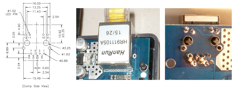
                          Investigating this issue it seems that my chinese ethernet shield has the wrong kind of terminating resistors on the ethernet line as described here.
                          So first I'll try to apply the common fix for that problem (change the resistors) and then I'll get back to you.

                          Btw thanks for the awesome support!

                          1 Reply Last reply
                          1
                          • gohanG Offline
                            gohanG Offline
                            gohan
                            Mod
                            wrote on last edited by
                            #13

                            Do you have a link for that fix? I may try to fix the faulty one that I have

                            1 Reply Last reply
                            0
                            • M Offline
                              M Offline
                              Misna
                              wrote on last edited by
                              #14

                              Hi!

                              Sure. Here is the link: https://forum.arduino.cc/index.php?topic=351477.15

                              There are many options for the fix but the easiest is defined by klggi on page2 (just solder 2 100ohm resistors on the backside of the ethernet connector).
                              I'll try to apply this fix tomorrow evening, I'll get back to you on how it went.

                              1 Reply Last reply
                              1
                              • gohanG Offline
                                gohanG Offline
                                gohan
                                Mod
                                wrote on last edited by
                                #15

                                On second thought maybe I'll skip the fixing, too much hassle to handle with SMD without proper tools :D

                                1 Reply Last reply
                                0
                                • M Offline
                                  M Offline
                                  Misna
                                  wrote on last edited by Misna
                                  #16

                                  @gohan check the post by klggi. No need to touch the SMD's, just solder 2 regular resistors to the backside of the connector.
                                  0_1490608510254_Terminations.png

                                  1 Reply Last reply
                                  1
                                  • M Offline
                                    M Offline
                                    Misna
                                    wrote on last edited by
                                    #17

                                    Evening!
                                    Happy to report that soldering the two resistors to the back fixed the problem!
                                    So no need to downgrade Arduino IDE etc..

                                    1 Reply Last reply
                                    2
                                    • gohanG Offline
                                      gohanG Offline
                                      gohan
                                      Mod
                                      wrote on last edited by
                                      #18

                                      in fact i have that 511 resistor in the back of connector. What resistors did you use?

                                      1 Reply Last reply
                                      0
                                      • M Offline
                                        M Offline
                                        Misna
                                        wrote on last edited by
                                        #19

                                        I used just regular 100Ohm resistors like this 0_1490677932738_img.jpg

                                        gohanG 1 Reply Last reply
                                        1
                                        • M Misna

                                          I used just regular 100Ohm resistors like this 0_1490677932738_img.jpg

                                          gohanG Offline
                                          gohanG Offline
                                          gohan
                                          Mod
                                          wrote on last edited by
                                          #20

                                          @Misna Added the 2 100Ohms resistors and it seems it is working. Maybe I could order some more shields and complain again they are faulty and have them refunded and do this quick repair :D
                                          At least it would be a little revenge on the many hours I lost with this faulty shield

                                          1 Reply Last reply
                                          0
                                          Reply
                                          • Reply as topic
                                          Log in to reply
                                          • Oldest to Newest
                                          • Newest to Oldest
                                          • Most Votes


                                          13

                                          Online

                                          11.7k

                                          Users

                                          11.2k

                                          Topics

                                          113.1k

                                          Posts


                                          Copyright 2025 TBD   |   Forum Guidelines   |   Privacy Policy   |   Terms of Service
                                          • Login

                                          • Don't have an account? Register

                                          • Login or register to search.
                                          • First post
                                            Last post
                                          0
                                          • MySensors
                                          • OpenHardware.io
                                          • Categories
                                          • Recent
                                          • Tags
                                          • Popular