Skip to content
  • MySensors
  • OpenHardware.io
  • Categories
  • Recent
  • Tags
  • Popular
Skins
  • Light
  • Brite
  • Cerulean
  • Cosmo
  • Flatly
  • Journal
  • Litera
  • Lumen
  • Lux
  • Materia
  • Minty
  • Morph
  • Pulse
  • Sandstone
  • Simplex
  • Sketchy
  • Spacelab
  • United
  • Yeti
  • Zephyr
  • Dark
  • Cyborg
  • Darkly
  • Quartz
  • Slate
  • Solar
  • Superhero
  • Vapor

  • Default (No Skin)
  • No Skin
Collapse
Brand Logo
  1. Home
  2. Hardware
  3. NRF24L01-PA-LNA in components library wrong?

NRF24L01-PA-LNA in components library wrong?

Scheduled Pinned Locked Moved Hardware
8 Posts 3 Posters 2.9k Views 3 Watching
  • Oldest to Newest
  • Newest to Oldest
  • Most Votes
Reply
  • Reply as topic
Log in to reply
This topic has been deleted. Only users with topic management privileges can see it.
  • E Offline
    E Offline
    elcaron
    wrote on last edited by
    #1

    Hi, I just found the KiCAD components library, just after I made my first design, so I already had a footprint made.
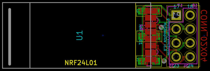
    Since I assumed that the footprints in the library are better controlled (I don't even have the device yet) I exchanged mine and found out that the two footprints are mirrored ... in mine, when looking at the module from the top, antenna on top, VCC is left. In the MySensors library, it is right.
    I made my footprint according to the image in the description of this auction I googled: http://www.ebay.com/itm/2Pcs-2-4G-NRF24L01-PA-LNA-Wireless-Module-Ceramic-Antenna-1-27mm-2-2-3-6V-/271968125413
    From the position of the antenna, I would say that VCC left ist the correct way, but I am surprised that the MySensors library is wrong ...

    1 Reply Last reply
    0
    • E Offline
      E Offline
      emc2
      Hardware Contributor
      wrote on last edited by
      #2

      Also the case of the footprint in the library.

      alt text

      1 Reply Last reply
      0
      • E Offline
        E Offline
        elcaron
        wrote on last edited by
        #3

        I think I found the problem. For some reason KiCAD puts the symbol of my version into he schematic, despite the fact that I am clearly choosing it from the MySensors lib. We chose different pin numbering. Apparently, KiCAD cannot deal with parts of the same name in different libraries.

        1 Reply Last reply
        0
        • L Offline
          L Offline
          LastSamurai
          Hardware Contributor
          wrote on last edited by
          #4

          @emc2 Where did you get that footprint from? I am only seeing a normal nrf24 with trough hole and a smd pa lna version. I do need the pa lna trough hole version though (and your picture looks like one).

          @elcaron So the pins in the official mysensors lib are right?

          1 Reply Last reply
          0
          • E Offline
            E Offline
            emc2
            Hardware Contributor
            wrote on last edited by
            #5

            @LastSamurai Originally I designed it but since then it has been added to the official mysensors-kicad repo https://github.com/mysensors-kicad
            Both regular SMD and PA+LNA SMD footprints and 3d shapes are verified to be working, I already used them quite a lot.

            1 Reply Last reply
            0
            • L Offline
              L Offline
              LastSamurai
              Hardware Contributor
              wrote on last edited by
              #6

              @emc2 Thanks but I was looking for the (non smd) trough hole PA+LNA version. The one you linked is only smd, right?

              1 Reply Last reply
              0
              • E Offline
                E Offline
                emc2
                Hardware Contributor
                wrote on last edited by
                #7

                Ah yes right.
                For non-smd they both have the same pinout, so you should be able to design it using the regular footprint, and then just plug a PA+LNA module in the header.

                1 Reply Last reply
                0
                • L Offline
                  L Offline
                  LastSamurai
                  Hardware Contributor
                  wrote on last edited by
                  #8

                  I did, I just needed the dimensions of the module for the antenna placement ;) Just measured mine though

                  1 Reply Last reply
                  0
                  Reply
                  • Reply as topic
                  Log in to reply
                  • Oldest to Newest
                  • Newest to Oldest
                  • Most Votes


                  27

                  Online

                  11.7k

                  Users

                  11.2k

                  Topics

                  113.1k

                  Posts


                  Copyright 2025 TBD   |   Forum Guidelines   |   Privacy Policy   |   Terms of Service
                  • Login

                  • Don't have an account? Register

                  • Login or register to search.
                  • First post
                    Last post
                  0
                  • MySensors
                  • OpenHardware.io
                  • Categories
                  • Recent
                  • Tags
                  • Popular