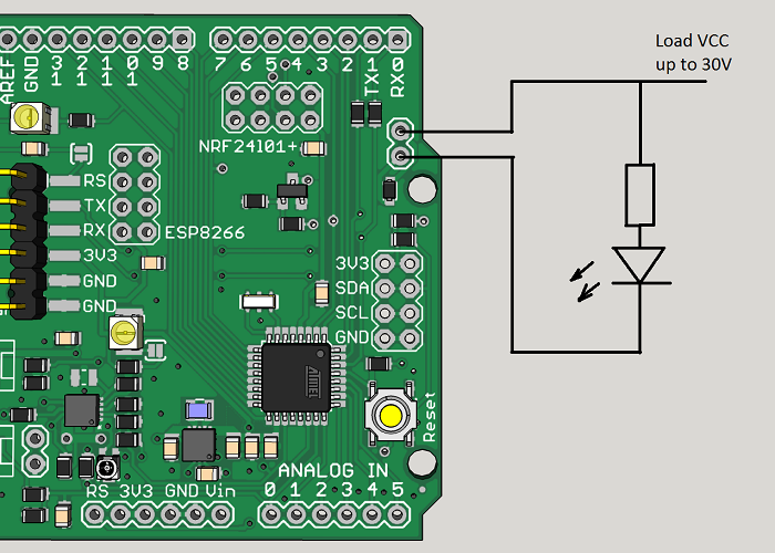
Mosfet with Ceech board
-
Hello,
I would like to use the mosfet of the Ceech board: ATmega328p board w/ NRF24l01+ socket LTC4079
In the doc is indicated that it is wired do digital 3.
I have modified the "blink without delay" sketchconst int MOSFET = 3; int loadState = LOW; unsigned long previousMillis = 0; const long interval = 2000; void setup() { // put your setup code here, to run once: pinMode(MOSFET, OUTPUT); digitalWrite(MOSFET, HIGH); Serial.begin(9600); } void loop() { unsigned long currentMillis = millis(); if (currentMillis - previousMillis >= interval) { // save the last time you blinked the LED previousMillis = currentMillis; // if the LED is off turn it on and vice-versa: if (loadState == LOW) { loadState = HIGH; } else { loadState = 0; } // set the LED with the ledState of the variable: digitalWrite(MOSFET, loadState); Serial.print("state: ");Serial.println(loadState); } }I don't understand how it works, I have tried to measure continuity with a voltmeter, I have tried to wire a led between vcc, cuting the gnd with the mosfet without success.
Does anyone would be explain how I can use it ?
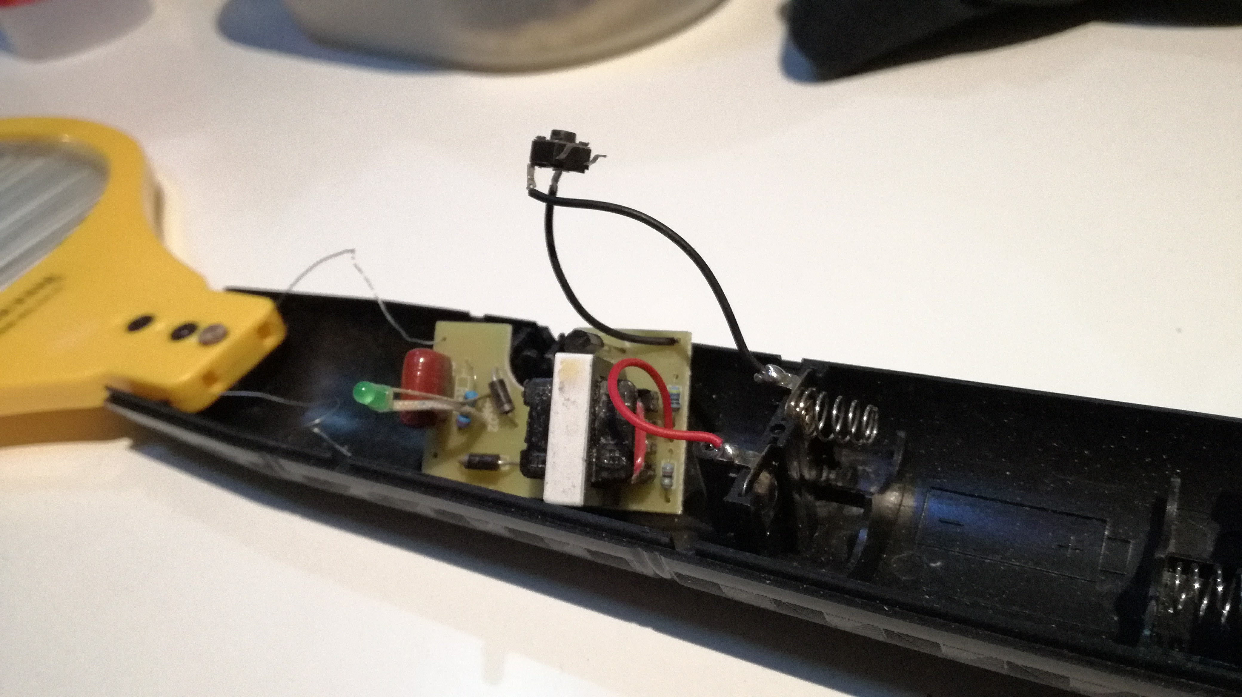
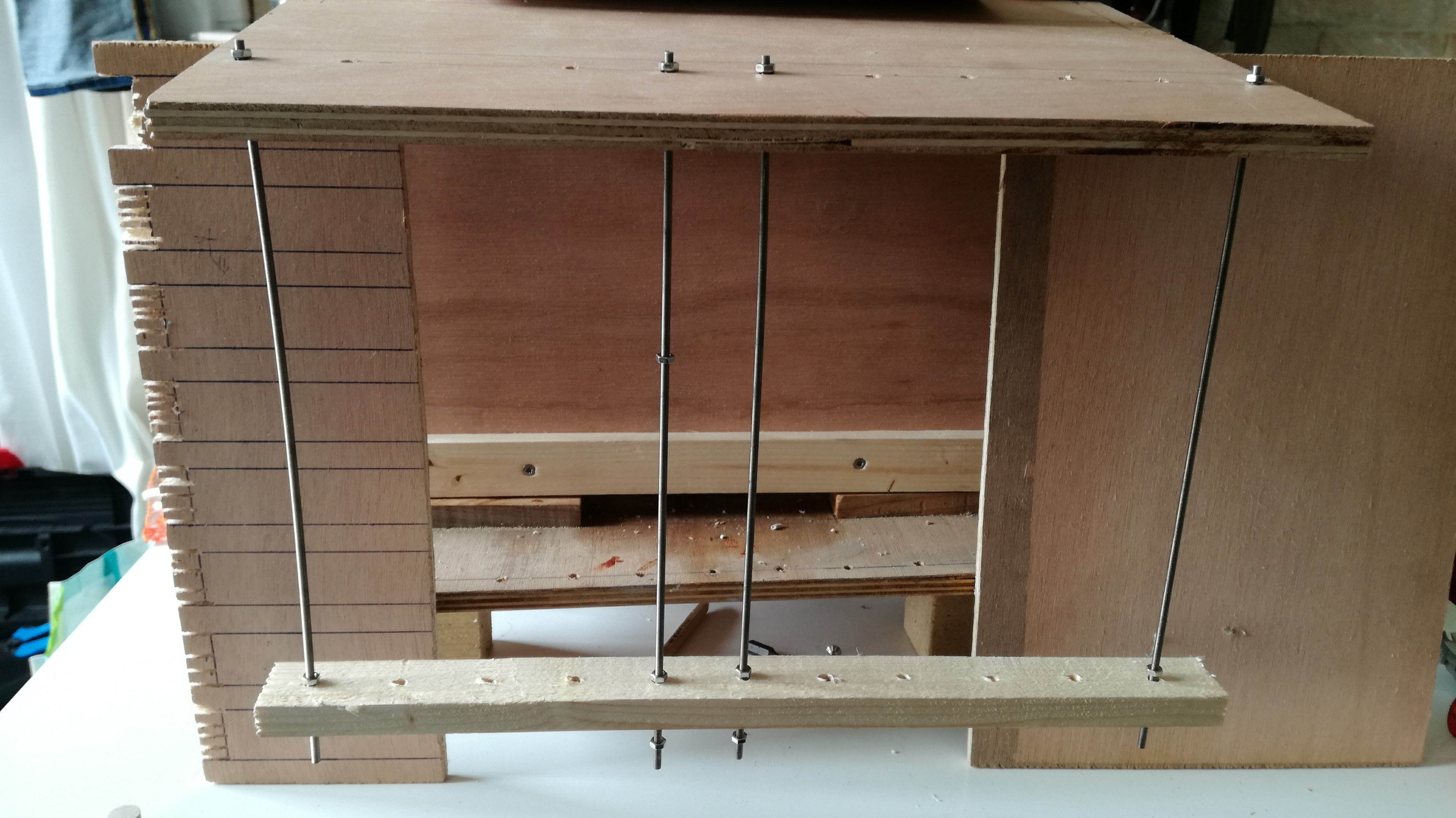
I would like to make an electrical barrier to protect my beehive from vespa velutina using a mosquito racket :
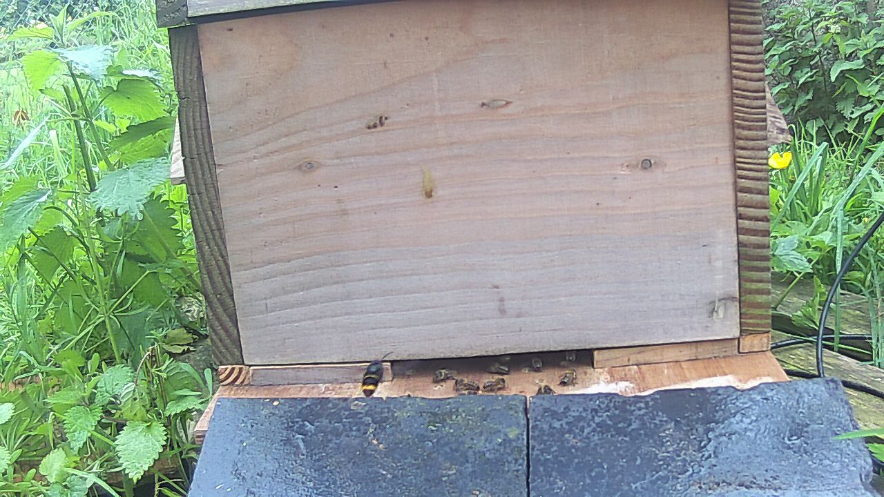
-
@Jodaille without looking at schematics I'd say you will kill/have killed the led if you don't put a current limiting resistor (few hundred ohms) in series with it.
-
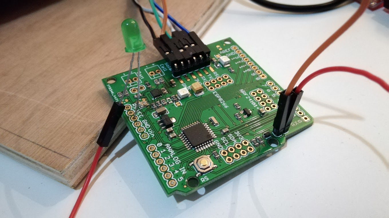
You need to connect the LED (+resistor) like this:
- Positive: Vcc Pin
- Negative: The pin with the orange/brown wire in your picture.
the mosfet onboard is N-channel, so it will switch the negative (GND) line.
-
Hello @Yveaux, hello @rvendrame: thank you.
the led is still alive

With the sketch , I can see the led blinking if it is wired between gnd and d3.
@rvendrame I should miss something because the led stay off with your instructions.
Maybe @ceech will see this my SOS

-
@Jodaille , it works for me, when wiring the led between Vcc and the non-named pin where you put that orange (or brown?) wire. There is where I found the MOSFET N-channel drain is connected.

-
Thank you @rvendrame ,
it works, I attach a Ceech's schema, using D4 instead of D3
