💬 NModule
-
IT WORKS!! Life is worth living again...
I've assembled now fourth module and it works, only different thing I did is that I have soldered the radio and power jumpers before connecting the module together. It could be that without jumpers essential component of all electronics (white smoke) gets out of the radio, not sure what happened. But it works!I was struggling a bit to figure out all components needed and all the steps, it might be helpful to have a "short guide", this is for my own reference of what I did in order to get CR2032 module for using with TempHumDoor shield:
Components needed [nModule]: pro mini, radio, nmodule board, 1 capacitor for radio larger then 4.7uf (I har only 10uf, I have ordered 47uf for future modules).
Assembling process
- Burn 1mhz bootloader on pro mini
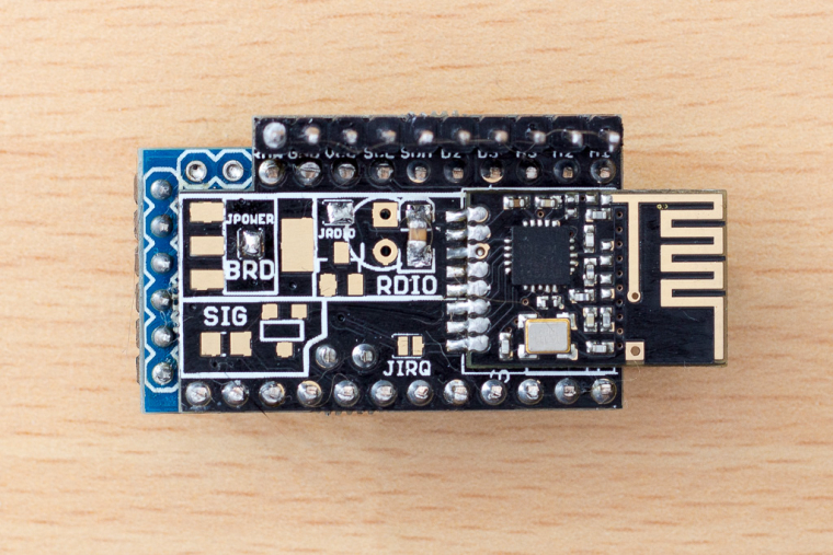
- solder two jumpers for jpower and jrdio
- solder the radio to the board
- Control that there is no connection between the radio pins, resistance is at least above 200Kohm (don't skip this part thinking it cannot happen to you, it will happen)
- Solder >4.7uf (f.eks. 10ud) smd.
- Solder all legs to arduino (except last two RXI and TX0, you will see them missing when you align nModule)
- Take off the plastic from the legs, before you solder it to the radio (do this BEFORE you solder it to the board)
- Solder arduino to nModule board
- Since the capacitor is very small, just check if there is no short between plus and minus (vcc and gnd) pins, as somehow I managed to short them on one module, it turned out that one of the caps was shorting it, probably by overhitting or something.
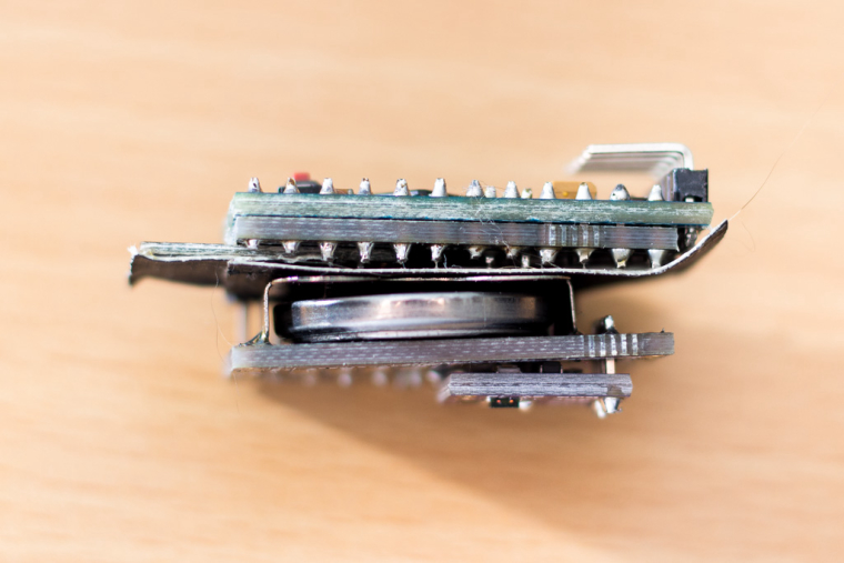
Upload mockMySensors sketch and check that node works properly (spare yourself a trouble, no point continuing further if this doesn't work) By this point you should have node looking like (better then) this:
TempHumidityLightDoor shield components: SMD SI7021 for temperature and humidity and a MAX44009 for light, two capacitors larger then 100uf (I used two of 100uf, waiting for 220 to come). And the work so far.
You basically solder these three/four components and the battery holder as described on the shield here https://www.openhardware.io/view/398/NModule-Temperature-Humidity-Light-Door-sensor-shield
I didn't yet solder LEDs, but they are accessible after assembling the module.
Then it looks like this: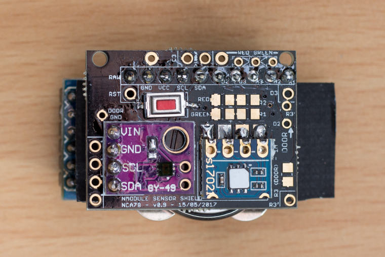
Now that nModule #1 is completed, you continue with other modules
-
If the "power" board is used, shall I keep the voltage regulator on Arduino? Without it, i think powering the board from RAW pin will not work.
-
If the "power" board is used, shall I keep the voltage regulator on Arduino? Without it, i think powering the board from RAW pin will not work.
@Haozhi-Wang it will depend how you connect things on the "power" board and/or what regulators you use on the NModule board.
There are 2 reasons to remove the regulator :- save energy if you are running on battery, it's not a big waste so if you are using CR123 or AAA you can keep it so it's possible for you to power from RAW with a higher voltage
- when powering from main, allow higher RAW voltage with a better voltage regulator on the NModule or the "power" board (on promini clones usually the maximum voltage is usually 9V)
There is a connection between the RAW pin of the promini (on the long side) and the RAW on the "power board", so whether it will work if you use a regulator on the "power" board and remove regulator on the promini will depend on the promini you use, if there is a track betwenn the 2 RAW pins or if it goes through the regulator.
I hope it answers your question, if not please describe more clearly what sensor you are building, with what power source and why you want to power it from RAW.
-
I love those shields... to bad they dont use MysX connector ;) Any thoughts about 2.0 rev?
Controller: Proxmox VM - Home Assistant
MySensors GW: Arduino Uno - W5100 Ethernet, Gw Shield Nrf24l01+ 2,4Ghz
MySensors GW: Arduino Uno - Gw Shield RFM69, 433mhz
RFLink GW - Arduino Mega + RFLink Shield, 433mhz -
I love those shields... to bad they dont use MysX connector ;) Any thoughts about 2.0 rev?
@sundberg84 I'm working on it :)
-
@Nca78 Thanks you for you detailed answer.
The power source i am going to use is a CR2032. My bad, I overlooked the three RAW, VCC and GND connectors (yellow) on the power board site.
For my case, i think shout circuit of JPOWER will be a even better solution -
@Nca78 Thanks you for you detailed answer.
The power source i am going to use is a CR2032. My bad, I overlooked the three RAW, VCC and GND connectors (yellow) on the power board site.
For my case, i think shout circuit of JPOWER will be a even better solution@Haozhi-Wang said in 💬 NModule:
@Nca78 Thanks you for you detailed answer.
The power source i am going to use is a CR2032.
Yes, for that case you need to short JPOWER and JBRD.
And don't forget to double check your USB adapter every time you connect it to your computer, to make sure you have selected 3.3V, else you will fry your radio with 5V. -
Hi there!
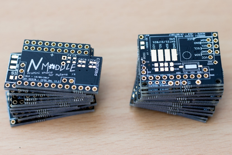
I've ordered 10 PCBs from iTEAD, so now... I'm plenty of them to do some tests.
Can you confirm these Minis are ok?
https://www.aliexpress.com/item/10pcs-ATMEGA328P-Pro-Mini-328-Mini-ATMEGA328-3-3V-16-MHz-for-Arduino-3-3V-16/32784455996.html?spm=a2g0s.13010208.99999999.271.swhWGMBtw, I have some battery boosters, I have used them already with success on breadboard. Have you got any experience about it? Do you think the PCB is hackable to integrate it?
Thanks!
atmega328p serial killer
HomeAssistant / gateway: ESP8266 & NRF24L01+ gateway -
Hi there!
I've ordered 10 PCBs from iTEAD, so now... I'm plenty of them to do some tests.
Can you confirm these Minis are ok?
https://www.aliexpress.com/item/10pcs-ATMEGA328P-Pro-Mini-328-Mini-ATMEGA328-3-3V-16-MHz-for-Arduino-3-3V-16/32784455996.html?spm=a2g0s.13010208.99999999.271.swhWGMBtw, I have some battery boosters, I have used them already with success on breadboard. Have you got any experience about it? Do you think the PCB is hackable to integrate it?
Thanks!
Can you confirm these Minis are ok?
https://www.aliexpress.com/item/10pcs-ATMEGA328P-Pro-Mini-328-Mini-ATMEGA328-3-3V-16-MHz-for-Arduino-3-3V-16/32784455996.html?spm=a2g0s.13010208.99999999.271.swhWGMYes they are ok, they seem to use the Sparkfun layout if I believe the reset button and the position of the A6/A7 pins. I use the boards with a smaller, rectangular reset button on my NModule PCB. The only problem I ever had with "different" ProMini board was the connection between the vcc of the programming header was cut when removing the voltage regulator so board was not powered anymore when using FTDI adapter.
Btw, I have some battery boosters, I have used them already with success on breadboard. Have you got any experience about it? Do you think the PCB is hackable to integrate it?
No, if you use a booster you need some extra caps for filtering the output, and a voltage divider to measure battery voltage, there's no space for that on NModule. I made NModule to have a compact "all included" board, so it's made to use low power sensors, that can run at low voltage so you don't need a booster.
If you really want to use a booster try EasyPCB. -
Thanks @Nca78 ! I'll order some a lot of 10. Just in case...
EasyPCB
You'r right. Thanks for this clarification - really don't need to use the boosters or have battery measurements, so I'll keep the sensors small as you designed.
atmega328p serial killer
HomeAssistant / gateway: ESP8266 & NRF24L01+ gateway -
-
or have battery measurements
You will have battery measurement, because you will power the atmega with the battery directly so it's possible to read Vcc.
When you use a booster Vcc is always the same so you need a voltage divider on the battery to know it's voltage.Sorry, n00b here! :( Thanks again, nca!
atmega328p serial killer
HomeAssistant / gateway: ESP8266 & NRF24L01+ gateway -
or have battery measurements
You will have battery measurement, because you will power the atmega with the battery directly so it's possible to read Vcc.
When you use a booster Vcc is always the same so you need a voltage divider on the battery to know it's voltage.Sorry, n00b here! :( Thanks again, nca!
-
@nca78 Hi, I am trying to use nmodule without batteries and connect 12v as a power source from usb breakout. I am not sure if I should remove the voltage regulator from pro mini? Also, should I add my own regulator to the nmodule (on BRD section)? Where should I connect my + and - from usb breakout to the nmodule? Thanks alot!
-
Hello,
what does that mean ?
@zmatokan said in 💬 NModule:connect 12v as a power source from usb breakout.
Do you power the board from 12V or 5V ?
Hi,
thanks for a very quick reply. I am trying to use a 12v external power source to power the arduino + radio + nmodule board. I tried soldering AMS1117 3,3V to the BRD part of the nmodule board, but when I connect my 12v (+ to the RAW pin and - to the ground) I do not get the regulated voltage at the nmodule shield breakout.
In essence I would like to make my nmodule board work without batteries, by using external power source (usb breakout that is connected to android 12v adapter). This 12v would be regulated by AMS1117 that I solder on BRD part of the board. This way both arduino and radio would get 3,3v and nmodule board would push that voltage to the shield trough vcc and gnd. Maybe I am looking at this the wrong way?
This the quote on your OpenHardware page that I am using as a guidance:
"footprint for an AMS1117 regulator (light blue) if your source voltage is too high for Arduino (> 5.5 V or > 3.3V for 8MHz version). AMS1117 can handle up to 15V and 800mA but it consumes a lot of power, so this regulator should be used only for "wired" power (12V, USB, ...) and never with batteries. If you are using only this regulator, the capacitor of the radio should be enough to keep it stable, but if you want to be on the safe side, you can use the capacitor footprints on the other side of the board: C6/C7 for input C8/C9 for output."
I managed to make my double AAA version to work without problems and kudos for great work!
Thanks alot!
@zmatokan Luckily NCA78 has a really good track record of picking low priced parts that are nonetheless really good parts. If worse came to worst, that AMS1117's thermal protection would turn the AMS1117 off until it could cool down rather than overheat to the point of destroying itself.
-
Hello,
what does that mean ?
@zmatokan said in 💬 NModule:connect 12v as a power source from usb breakout.
Do you power the board from 12V or 5V ?
Hi,
thanks for a very quick reply. I am trying to use a 12v external power source to power the arduino + radio + nmodule board. I tried soldering AMS1117 3,3V to the BRD part of the nmodule board, but when I connect my 12v (+ to the RAW pin and - to the ground) I do not get the regulated voltage at the nmodule shield breakout.
In essence I would like to make my nmodule board work without batteries, by using external power source (usb breakout that is connected to android 12v adapter). This 12v would be regulated by AMS1117 that I solder on BRD part of the board. This way both arduino and radio would get 3,3v and nmodule board would push that voltage to the shield trough vcc and gnd. Maybe I am looking at this the wrong way?
This the quote on your OpenHardware page that I am using as a guidance:
"footprint for an AMS1117 regulator (light blue) if your source voltage is too high for Arduino (> 5.5 V or > 3.3V for 8MHz version). AMS1117 can handle up to 15V and 800mA but it consumes a lot of power, so this regulator should be used only for "wired" power (12V, USB, ...) and never with batteries. If you are using only this regulator, the capacitor of the radio should be enough to keep it stable, but if you want to be on the safe side, you can use the capacitor footprints on the other side of the board: C6/C7 for input C8/C9 for output."
I managed to make my double AAA version to work without problems and kudos for great work!
Thanks alot!
@zmatokan ok it's clear now.
So yes you should remove the regulator on the pro-mini, because it's also doing voltage regulation from RAW to VCC and it can't work in parallel with the AMS1117.
Then if you have added ceramic capacitors (one for input, one for output, 1uA each) and connect 12V on RAW and GND you should have 3.3V on VCC. Then you can short JRADIO to send the 3.3V to the radio module.