💬 NModule
-
Hello,
what does that mean ?
@zmatokan said in 💬 NModule:connect 12v as a power source from usb breakout.
Do you power the board from 12V or 5V ?
Hi,
thanks for a very quick reply. I am trying to use a 12v external power source to power the arduino + radio + nmodule board. I tried soldering AMS1117 3,3V to the BRD part of the nmodule board, but when I connect my 12v (+ to the RAW pin and - to the ground) I do not get the regulated voltage at the nmodule shield breakout.
In essence I would like to make my nmodule board work without batteries, by using external power source (usb breakout that is connected to android 12v adapter). This 12v would be regulated by AMS1117 that I solder on BRD part of the board. This way both arduino and radio would get 3,3v and nmodule board would push that voltage to the shield trough vcc and gnd. Maybe I am looking at this the wrong way?
This the quote on your OpenHardware page that I am using as a guidance:
"footprint for an AMS1117 regulator (light blue) if your source voltage is too high for Arduino (> 5.5 V or > 3.3V for 8MHz version). AMS1117 can handle up to 15V and 800mA but it consumes a lot of power, so this regulator should be used only for "wired" power (12V, USB, ...) and never with batteries. If you are using only this regulator, the capacitor of the radio should be enough to keep it stable, but if you want to be on the safe side, you can use the capacitor footprints on the other side of the board: C6/C7 for input C8/C9 for output."
I managed to make my double AAA version to work without problems and kudos for great work!
Thanks alot!
@zmatokan Luckily NCA78 has a really good track record of picking low priced parts that are nonetheless really good parts. If worse came to worst, that AMS1117's thermal protection would turn the AMS1117 off until it could cool down rather than overheat to the point of destroying itself.
-
Hello,
what does that mean ?
@zmatokan said in 💬 NModule:connect 12v as a power source from usb breakout.
Do you power the board from 12V or 5V ?
Hi,
thanks for a very quick reply. I am trying to use a 12v external power source to power the arduino + radio + nmodule board. I tried soldering AMS1117 3,3V to the BRD part of the nmodule board, but when I connect my 12v (+ to the RAW pin and - to the ground) I do not get the regulated voltage at the nmodule shield breakout.
In essence I would like to make my nmodule board work without batteries, by using external power source (usb breakout that is connected to android 12v adapter). This 12v would be regulated by AMS1117 that I solder on BRD part of the board. This way both arduino and radio would get 3,3v and nmodule board would push that voltage to the shield trough vcc and gnd. Maybe I am looking at this the wrong way?
This the quote on your OpenHardware page that I am using as a guidance:
"footprint for an AMS1117 regulator (light blue) if your source voltage is too high for Arduino (> 5.5 V or > 3.3V for 8MHz version). AMS1117 can handle up to 15V and 800mA but it consumes a lot of power, so this regulator should be used only for "wired" power (12V, USB, ...) and never with batteries. If you are using only this regulator, the capacitor of the radio should be enough to keep it stable, but if you want to be on the safe side, you can use the capacitor footprints on the other side of the board: C6/C7 for input C8/C9 for output."
I managed to make my double AAA version to work without problems and kudos for great work!
Thanks alot!
@zmatokan ok it's clear now.
So yes you should remove the regulator on the pro-mini, because it's also doing voltage regulation from RAW to VCC and it can't work in parallel with the AMS1117.
Then if you have added ceramic capacitors (one for input, one for output, 1uA each) and connect 12V on RAW and GND you should have 3.3V on VCC. Then you can short JRADIO to send the 3.3V to the radio module. -
@zmatokan Luckily NCA78 has a really good track record of picking low priced parts that are nonetheless really good parts. If worse came to worst, that AMS1117's thermal protection would turn the AMS1117 off until it could cool down rather than overheat to the point of destroying itself.
-
@zmatokan ok it's clear now.
So yes you should remove the regulator on the pro-mini, because it's also doing voltage regulation from RAW to VCC and it can't work in parallel with the AMS1117.
Then if you have added ceramic capacitors (one for input, one for output, 1uA each) and connect 12V on RAW and GND you should have 3.3V on VCC. Then you can short JRADIO to send the 3.3V to the radio module. -
@zmatokan ok it's clear now.
So yes you should remove the regulator on the pro-mini, because it's also doing voltage regulation from RAW to VCC and it can't work in parallel with the AMS1117.
Then if you have added ceramic capacitors (one for input, one for output, 1uA each) and connect 12V on RAW and GND you should have 3.3V on VCC. Then you can short JRADIO to send the 3.3V to the radio module.@Nca78 Hi, looks like I am doing something wrong in my last attempts to use your design with 12v external power supply.
I am using:
- Arduino 5v, 16hz
- AMS 1117 5.0V
- 662K XC6206 - 5v to 3.3v voltage regulator for radio
- 10UF-16V CAP for radio
- NRF24L01SMD
As you can see on a picture, I am using a terminal block where i push 12v.
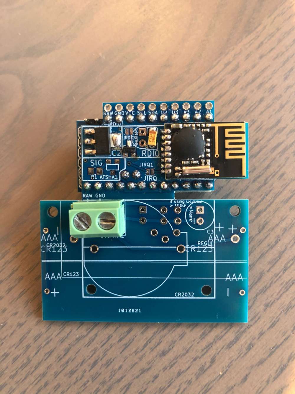
When I connect the power to the terminal, my Voltage regulator get veeery hot and nothing works.
When I connected my FTDI to try to upload a sketch, a capacitor on arduino got fried. You can see it in the next pic.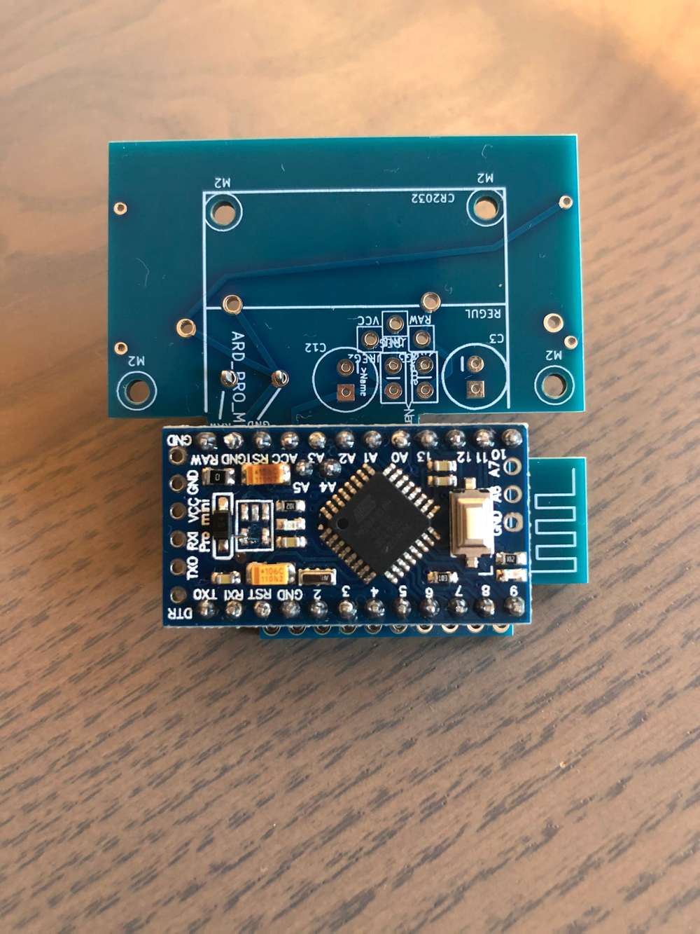
This happened on tree of my boards.
Can you please take a look and try to see where the problem might be?
Thanks alot!
-
@Nca78 Hi, looks like I am doing something wrong in my last attempts to use your design with 12v external power supply.
I am using:
- Arduino 5v, 16hz
- AMS 1117 5.0V
- 662K XC6206 - 5v to 3.3v voltage regulator for radio
- 10UF-16V CAP for radio
- NRF24L01SMD
As you can see on a picture, I am using a terminal block where i push 12v.
When I connect the power to the terminal, my Voltage regulator get veeery hot and nothing works.
When I connected my FTDI to try to upload a sketch, a capacitor on arduino got fried. You can see it in the next pic.This happened on tree of my boards.
Can you please take a look and try to see where the problem might be?
Thanks alot!
587488927515_IMG_3554.jpeg](Uploading 100%)
Hello, I cannot see the picture, I think something went wrong during the upload...
Can you confirm that you didn't solder the jumpers ? Did you solder the input/output capacitors for each regulator on the other side of the board ? -
587488927515_IMG_3554.jpeg](Uploading 100%)
Hello, I cannot see the picture, I think something went wrong during the upload...
Can you confirm that you didn't solder the jumpers ? Did you solder the input/output capacitors for each regulator on the other side of the board ?@Nca78 Thanks for the quick reply.
I hope you will be able to see the images now:
What jumpers are you referring to?
-
@Nca78 Thanks for the quick reply.
I hope you will be able to see the images now:
What jumpers are you referring to?
What jumpers are you referring to?
JPOWER and JRDIO, they should be unsoldered if you are using regulators.
I see JRDIO is not soldered, I can't see JPOWER as it's below the AMS1117, but I supposed you didn't solder it.Components seem ok, can you explain the problem ? Do you have 5V at the output of the AMS117 and 3.3V at the output of the XC6206 ?
[edit] those "blob" modules are usually of very poor quality, so if you have the right voltages but can't make a radio connection, they might be the reason...
-
What jumpers are you referring to?
JPOWER and JRDIO, they should be unsoldered if you are using regulators.
I see JRDIO is not soldered, I can't see JPOWER as it's below the AMS1117, but I supposed you didn't solder it.Components seem ok, can you explain the problem ? Do you have 5V at the output of the AMS117 and 3.3V at the output of the XC6206 ?
[edit] those "blob" modules are usually of very poor quality, so if you have the right voltages but can't make a radio connection, they might be the reason...
@Nca78 I didn't soldier JPOWER either.
Problem is that when I connect 12v to terminal block, my voltage regulator gets very hot and arduino is just showing red led ad not responding to reset.
If I try to connect FTDI cable to upload a sketch, I got my CAP on arduino fried as you can see in the image.If I try the same thing on simple nmodule (without battery part), it works when I push 12v to RAW and GND.
Maybe the battery pcb part is making problems? Should I soldier C4...C9 on the back of the nmodule pcb? -
@Nca78 I didn't soldier JPOWER either.
Problem is that when I connect 12v to terminal block, my voltage regulator gets very hot and arduino is just showing red led ad not responding to reset.
If I try to connect FTDI cable to upload a sketch, I got my CAP on arduino fried as you can see in the image.If I try the same thing on simple nmodule (without battery part), it works when I push 12v to RAW and GND.
Maybe the battery pcb part is making problems? Should I soldier C4...C9 on the back of the nmodule pcb?@zmatokan sorry I complained about your missing pictures and didn't notice you had explained the problem in your initial message.
A very hot regulator sounds like a short circuit on it's output. Is the red led on at full level or dimmed ? Can you confirm which regulator is getting very hot ?
Burnt tantalum capacitor is either voltage higher than rated voltage or reverse polarity. This capacitor is I think connected between RAW and GND, so I don't see how this could happen, did you have 12V on terminal block when you connected the FTDI ?For the source of the short circuit (can you check resistance between VCC and GND, and radio VCC and GND ? Not a good idea to do that usually but it will easily confirm the problem here) I have no idea. I don't think it comes from the "power/battery" part of the board, it's pretty basic and it would short RAW not VCC. You could have a problem with radio footprint (but if it's the same module on the non 12V powered board, it's not the reason), or a short between some via on the radio module with the second radio footprint that is below it (red color on picture below)
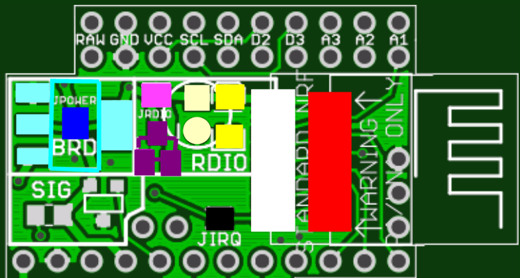
You should have at least one capacitor for each couple of footprint for input (C6/C7) and output (C8/C9) of the AMS1117. It's not what is causing the problem now, but it will make the power more stable.
-
@zmatokan sorry I complained about your missing pictures and didn't notice you had explained the problem in your initial message.
A very hot regulator sounds like a short circuit on it's output. Is the red led on at full level or dimmed ? Can you confirm which regulator is getting very hot ?
Burnt tantalum capacitor is either voltage higher than rated voltage or reverse polarity. This capacitor is I think connected between RAW and GND, so I don't see how this could happen, did you have 12V on terminal block when you connected the FTDI ?For the source of the short circuit (can you check resistance between VCC and GND, and radio VCC and GND ? Not a good idea to do that usually but it will easily confirm the problem here) I have no idea. I don't think it comes from the "power/battery" part of the board, it's pretty basic and it would short RAW not VCC. You could have a problem with radio footprint (but if it's the same module on the non 12V powered board, it's not the reason), or a short between some via on the radio module with the second radio footprint that is below it (red color on picture below)
You should have at least one capacitor for each couple of footprint for input (C6/C7) and output (C8/C9) of the AMS1117. It's not what is causing the problem now, but it will make the power more stable.
@Nca78 Thanks a lot for a quick and detailed response.
I tried last night with the regular nmodule pcb (without battery part) and that one didn't work either (seems like the ones that were working before were connected to 5v power supply, not 12v).
Arduino led is at full level and radio is not connecting.
Please confirm that you see this picture:
Should this pads be connected like this? C7 and C6 are connected, not sure if its the problem with the manufacturing or is it meant to be connected?
Another question is: should I connect pads in YELLOW or RED direction? (probably stupid question)
So far I connected them in yellow direction C7->C7
Could this be connected with the problem?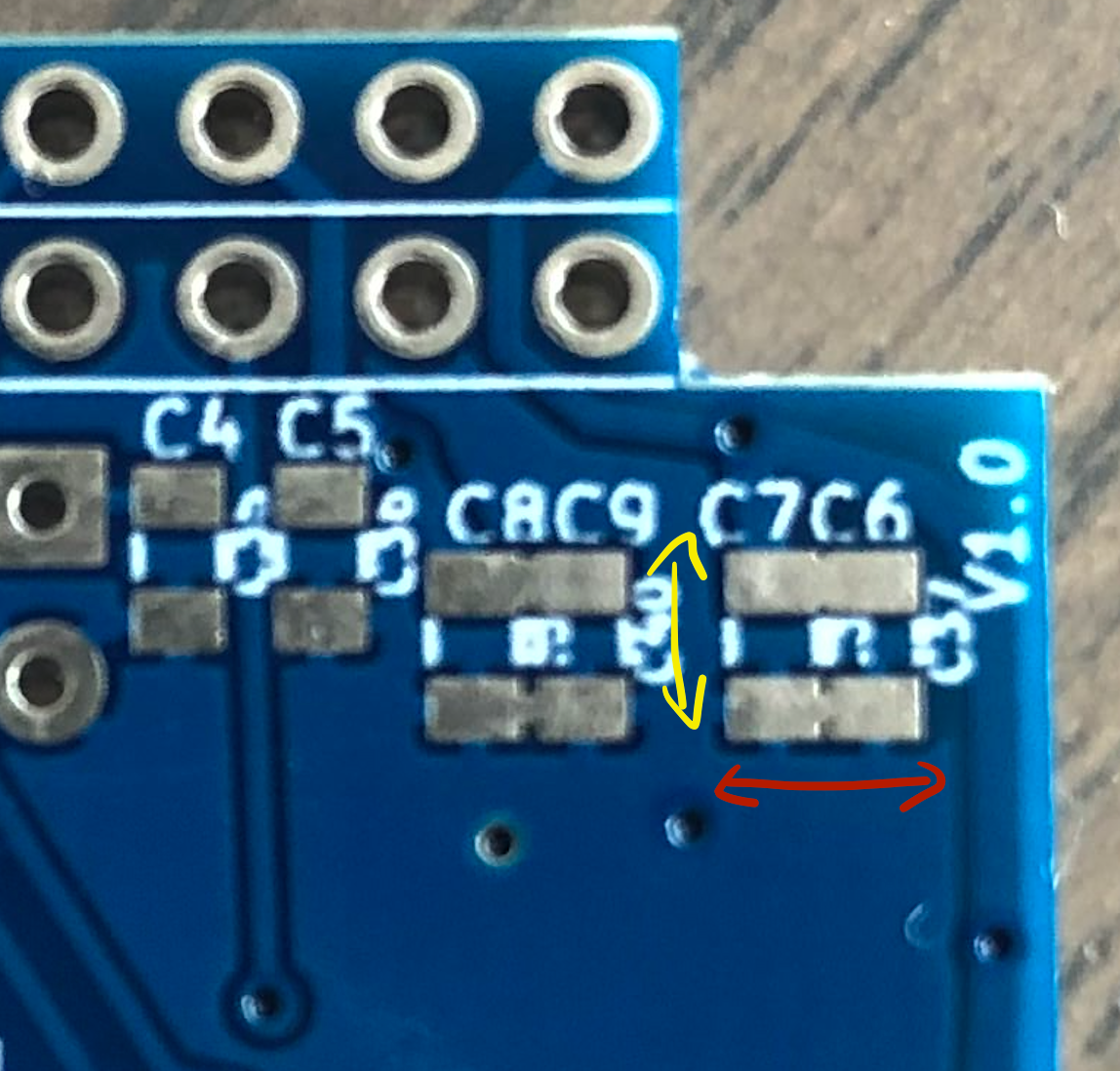
If this 12v does not work out, do you have any other advice?
What I want to do is to use your design without batteries.
It is very small and will fit into a wall socket where I would connect it to some DC power supply.
This DC powersupply will be converted from 220V AC to 12V or maybe 5v.
If I use 5v powersupply, can I still connect 3,3v arduino and sensors to it and how would be the best way?Thanks a lot!
-
@Nca78 Thanks a lot for a quick and detailed response.
I tried last night with the regular nmodule pcb (without battery part) and that one didn't work either (seems like the ones that were working before were connected to 5v power supply, not 12v).
Arduino led is at full level and radio is not connecting.
Please confirm that you see this picture:
Should this pads be connected like this? C7 and C6 are connected, not sure if its the problem with the manufacturing or is it meant to be connected?
Another question is: should I connect pads in YELLOW or RED direction? (probably stupid question)
So far I connected them in yellow direction C7->C7
Could this be connected with the problem?If this 12v does not work out, do you have any other advice?
What I want to do is to use your design without batteries.
It is very small and will fit into a wall socket where I would connect it to some DC power supply.
This DC powersupply will be converted from 220V AC to 12V or maybe 5v.
If I use 5v powersupply, can I still connect 3,3v arduino and sensors to it and how would be the best way?Thanks a lot!
@zmatokan yellow arrow is the right way. Connections between C6/C7 and C8/C9 is normal, I doubled the footprint but you can put only one capacitor on each of the pair of footprints, just make sure the values match the data sheet.
12V might be too much if you have really cheap AMS1117 clones, but I have no problem with mine (I have a nmodule with the DC Fan/PWM shield running on 12V and it's been controlling the 12V fan for 2 years without problem).
You can use a 5V power supply, and use a 3.3V AMS1117 for board, radio and sensors. That's what I do usually, a 8MHz arduino is enough for most sensor uses, 16MHz is only needed if you have a demanding user interface like a color LCD or some complicated calculations, but in that case it's a better idea to switch to ARM microcontrollers.
So solution would be 5V source, 3.3V AMS1117, and no regulator for radio.
Have you tried to unsolder the radio on one of the non-working module to see if you can at least program/run the arduino ? In that case it would narrow down the problem to the radio modules.
Also, checking the voltage output of both of the regulators would help. -
@zmatokan yellow arrow is the right way. Connections between C6/C7 and C8/C9 is normal, I doubled the footprint but you can put only one capacitor on each of the pair of footprints, just make sure the values match the data sheet.
12V might be too much if you have really cheap AMS1117 clones, but I have no problem with mine (I have a nmodule with the DC Fan/PWM shield running on 12V and it's been controlling the 12V fan for 2 years without problem).
You can use a 5V power supply, and use a 3.3V AMS1117 for board, radio and sensors. That's what I do usually, a 8MHz arduino is enough for most sensor uses, 16MHz is only needed if you have a demanding user interface like a color LCD or some complicated calculations, but in that case it's a better idea to switch to ARM microcontrollers.
So solution would be 5V source, 3.3V AMS1117, and no regulator for radio.
Have you tried to unsolder the radio on one of the non-working module to see if you can at least program/run the arduino ? In that case it would narrow down the problem to the radio modules.
Also, checking the voltage output of both of the regulators would help.@Nca78 Thanks! I'l check what you suggested.
If I would use:
- 5v power supply
- 5v arduino
- 5v motion sensor
i would need to
- remove onboard arduino voltage regulator
- connect RAW and GND to the 5v powersupply
- add radio volt regulator and capacitor
- soldier JPOWER
And if i use:
5v power supply
3,3v arduino
3v sensori would need to:
- remove onboard arduino voltage regulator
- connect RAW and GND to the 5v powersupply
- add 3.3V AMS1117
- add radio capacitor
- soldier JRADIO
Thanks man!
-
@Nca78 Thanks! I'l check what you suggested.
If I would use:
- 5v power supply
- 5v arduino
- 5v motion sensor
i would need to
- remove onboard arduino voltage regulator
- connect RAW and GND to the 5v powersupply
- add radio volt regulator and capacitor
- soldier JPOWER
And if i use:
5v power supply
3,3v arduino
3v sensori would need to:
- remove onboard arduino voltage regulator
- connect RAW and GND to the 5v powersupply
- add 3.3V AMS1117
- add radio capacitor
- soldier JRADIO
Thanks man!
If I would use:
- 5v power supply
- 5v arduino
- 5v motion sensor
i would need to
- remove onboard arduino voltage regulator
- connect RAW and GND to the 5v powersupply
- add radio volt regulator and capacitor
- soldier JPOWER
Yes. If your sensor can work with the voltage drop of the arduino regulator (I think yes), you can also keep it and leave JPOWER open. Less risky and you might have a "cleaner" power for the motion sensor.
And if i use:
5v power supply
3,3v arduino
3v sensori would need to:
- remove onboard arduino voltage regulator
- connect RAW and GND to the 5v powersupply
- add 3.3V AMS1117
- add radio capacitor
- soldier JRADIO
No, with a normal SMD radio the onboard regulator of the promini will be enough to supply power to board + radio + i2C sensors. So keep the arduino regulator, don't add an AMS1117, leave JPOWER opened, solder JRADIO.
-
Hi there! In these days I got some boards from my drawer - I spare quite a lot, I ordered 10 panelized one, so I have 40 NModules! :O :smiley:
4 sensors are yet running on battery (2 on CR2032 and 2 with with 2xAA). The fifth module had an accident and I need to program it via SPI. is it safe to flash it with the antenna still soldered? -
Hi there! In these days I got some boards from my drawer - I spare quite a lot, I ordered 10 panelized one, so I have 40 NModules! :O :smiley:
4 sensors are yet running on battery (2 on CR2032 and 2 with with 2xAA). The fifth module had an accident and I need to program it via SPI. is it safe to flash it with the antenna still soldered?Hi there! In these days I got some boards from my drawer - I spare quite a lot, I ordered 10 panelized one, so I have 40 NModules! :O :smiley:
4 sensors are yet running on battery (2 on CR2032 and 2 with with 2xAA). The fifth module had an accident and I need to program it via SPI. is it safe to flash it with the antenna still soldered?Haha that's a lot of boards. May I know what the accident was ? There was a case of a nmodule having a shortcut when manipulated, is it something similar ?
The radio SPI pins can handle 5V but not it's power supply. So as you have no regulator on radio for these boards, I see 3 choices :- best one = use a programmer running at 3.3V and you can power the board & radio with it. 100% safe. You can do this with the ArduinoISP sketch, a 3.3V pro mini and a ftdi adapter.
- if you only have a 5V powered programmer, power the board separately and connect only the SPI pins with the 5V programmer. But this is out of spec as the voltage on SPI pins will be higher than VCC + 0.5V
- open the JRDIO jumper so that the radio is not connected to VCC and use 5V programmer for SPI pins + power supply of the board. In that case to respect the datasheet of NRF24 you need to supply separately at least 3V to VCC radio, else you are in the same situation than point 2, but with the radio and that is I think a worse situation so in that case solution 2. is safer.
-
Hi there! In these days I got some boards from my drawer - I spare quite a lot, I ordered 10 panelized one, so I have 40 NModules! :O :smiley:
4 sensors are yet running on battery (2 on CR2032 and 2 with with 2xAA). The fifth module had an accident and I need to program it via SPI. is it safe to flash it with the antenna still soldered?Haha that's a lot of boards. May I know what the accident was ? There was a case of a nmodule having a shortcut when manipulated, is it something similar ?
The radio SPI pins can handle 5V but not it's power supply. So as you have no regulator on radio for these boards, I see 3 choices :- best one = use a programmer running at 3.3V and you can power the board & radio with it. 100% safe. You can do this with the ArduinoISP sketch, a 3.3V pro mini and a ftdi adapter.
- if you only have a 5V powered programmer, power the board separately and connect only the SPI pins with the 5V programmer. But this is out of spec as the voltage on SPI pins will be higher than VCC + 0.5V
- open the JRDIO jumper so that the radio is not connected to VCC and use 5V programmer for SPI pins + power supply of the board. In that case to respect the datasheet of NRF24 you need to supply separately at least 3V to VCC radio, else you are in the same situation than point 2, but with the radio and that is I think a worse situation so in that case solution 2. is safer.
Haha that's a lot of boards. May I know what the accident was ? There was a case of a nmodule having a shortcut when manipulated, is it something similar ?
Oh, easy! I already had soldered TX/RX pins and the angled ones (towards the atmega). I decide to take them off and reverse the angled... Iron's temperature was quite high... Some tracks got as bright as old 100W bulbs filament! :D
The radio SPI pins can handle 5V but not it's power supply. So as you have no regulator on radio for these boards, I see 3 choices :
- best one = use a programmer running at 3.3V and you can power the board & radio with it. 100% safe. You can do this with the ArduinoISP sketch, a 3.3V pro mini and a ftdi adapter.
- if you only have a 5V powered programmer, power the board separately and connect only the SPI pins with the 5V programmer. But this is out of spec as the voltage on SPI pins will be higher than VCC + 0.5V
- open the JRDIO jumper so that the radio is not connected to VCC and use 5V programmer for SPI pins + power supply of the board. In that case to respect the datasheet of NRF24 you need to supply separately at least 3V to VCC radio, else you are in the same situation than point 2, but with the radio and that is I think a worse situation so in that case solution 2. is safer.
I'm yet programming it with ArduinoISP on a genuine UNO, so I'm safe. I'll solder the SMD antenna ASAP, the TH one isn't bearable once you see how slim the node gets with your PCB!
-
Ok, just for record: be very very very very very carefull when desoldering the regulator+led+resistance. Do it before soldering the ping legs on module: I had a pair of nodes, correctly running, beatyfully soldered, legs trimmed... and darn, dunno what I did on tracks, they are not powering up anymore.
Luckily I could desolder the antenna from under the PCB and stick on another (the first I told) and put the other as spare.Oh, I love DIY when I fix my errors! :laughing:
{update: one sensor died yesterday. Maybe my Minis are too cheap? }
-
If I would use:
- 5v power supply
- 5v arduino
- 5v motion sensor
i would need to
- remove onboard arduino voltage regulator
- connect RAW and GND to the 5v powersupply
- add radio volt regulator and capacitor
- soldier JPOWER
Yes. If your sensor can work with the voltage drop of the arduino regulator (I think yes), you can also keep it and leave JPOWER open. Less risky and you might have a "cleaner" power for the motion sensor.
And if i use:
5v power supply
3,3v arduino
3v sensori would need to:
- remove onboard arduino voltage regulator
- connect RAW and GND to the 5v powersupply
- add 3.3V AMS1117
- add radio capacitor
- soldier JRADIO
No, with a normal SMD radio the onboard regulator of the promini will be enough to supply power to board + radio + i2C sensors. So keep the arduino regulator, don't add an AMS1117, leave JPOWER opened, solder JRADIO.
-
@Nca78 Thanks man! I managed to make it work. Seems like the problem was with radio modules. Now it works fine!
Hello! It looks like you're interested in this conversation, but you don't have an account yet.
Getting fed up of having to scroll through the same posts each visit? When you register for an account, you'll always come back to exactly where you were before, and choose to be notified of new replies (either via email, or push notification). You'll also be able to save bookmarks and upvote posts to show your appreciation to other community members.
With your input, this post could be even better 💗
Register Login