ACS712 strange values when measuring 3D printer power consumption
-
Not sure if this is the right forum but essentially building this on MySensors node so here it goes.
So far I have implemented several ACS712 AC measurement nodes around the house. After calibration the accuracy is around 10-20W which has been good enough for me. However now I'm really having a trouble to understand why the values it provides are way of the chart. Information about this node:-
My computer room has 2xPCs, Xbox, 2x3D printer, Raspberry 3 running Domoticz, Gigabit switch and home theatre amplifier
-
There comes one 230V/50Hz power intake to a small UPS. UPS provides backup power only to the switch and the other PC. All other devices are connected only through UPS power surge protection outlets. There are couple of multiple output extension power cords to achieve this.
-
Now if I use anything else than the 3D printers the power meter shows realistic values. If I turn either of the 3D printers on the values goes all crazy. I have used my Belkin power meter as reference point and with 3D printer on it shows around 200W and arduino +680W. If I turn the both printers on, the values goes even more separate. Blink node implemented to the electric meter of the house backups Belkin's "reference" values.
-
I have tried to separate the arduino power meter so that it is at least one meter away from the 3D printers but no difference.
-
The other 3D printer (Kossel) uses normal computer supply and the other (official Prusa) probably quite similar. Common thing is that they both are open type printers and they have the same hotends. Hotend takes 12V 5A and Kossel heated bed around 12V 11A, Prusa probably something similar.
I have tried to use different exension cords, pluggin in different apparatus (hair dryer is my common calibration device) but currently I have no idea what's going on. Only thing I could imagine would be something related to the magnetic fields these quite much DC current consuming printers generate. Arduino is currently sitting about one meter from them, but could it still somehow disturb the ACS712? Also I have checked that the Arduino Nano's 5V voltage stays very stable and shouldn't affect the calculations.
Edit. I plugged Prusa to another wall outlet about one meter away (same phase/fuse though) and turned it on -> no affect to the Arduino sitting in the same place. So it cannot be my magnetic mumbo jambo theory. So now I'm even more lost...do they generate some noise to the line or...??? :confused:
-
-
Not sure if this is the right forum but essentially building this on MySensors node so here it goes.
So far I have implemented several ACS712 AC measurement nodes around the house. After calibration the accuracy is around 10-20W which has been good enough for me. However now I'm really having a trouble to understand why the values it provides are way of the chart. Information about this node:-
My computer room has 2xPCs, Xbox, 2x3D printer, Raspberry 3 running Domoticz, Gigabit switch and home theatre amplifier
-
There comes one 230V/50Hz power intake to a small UPS. UPS provides backup power only to the switch and the other PC. All other devices are connected only through UPS power surge protection outlets. There are couple of multiple output extension power cords to achieve this.
-
Now if I use anything else than the 3D printers the power meter shows realistic values. If I turn either of the 3D printers on the values goes all crazy. I have used my Belkin power meter as reference point and with 3D printer on it shows around 200W and arduino +680W. If I turn the both printers on, the values goes even more separate. Blink node implemented to the electric meter of the house backups Belkin's "reference" values.
-
I have tried to separate the arduino power meter so that it is at least one meter away from the 3D printers but no difference.
-
The other 3D printer (Kossel) uses normal computer supply and the other (official Prusa) probably quite similar. Common thing is that they both are open type printers and they have the same hotends. Hotend takes 12V 5A and Kossel heated bed around 12V 11A, Prusa probably something similar.
I have tried to use different exension cords, pluggin in different apparatus (hair dryer is my common calibration device) but currently I have no idea what's going on. Only thing I could imagine would be something related to the magnetic fields these quite much DC current consuming printers generate. Arduino is currently sitting about one meter from them, but could it still somehow disturb the ACS712? Also I have checked that the Arduino Nano's 5V voltage stays very stable and shouldn't affect the calculations.
Edit. I plugged Prusa to another wall outlet about one meter away (same phase/fuse though) and turned it on -> no affect to the Arduino sitting in the same place. So it cannot be my magnetic mumbo jambo theory. So now I'm even more lost...do they generate some noise to the line or...??? :confused:
@Sushukka So I am trying to understand how you have your ACS712 sensor(s) connected. Do you have more than one device connected to one ACS712? If so, what devices do you have connected to it?
There are a few different ACS712 modules that range from 5 amps to 30 amps. If you have multiple devices connected to a single ACS712 5 amp module, your problem may be that you are drawing too much power which may be what's flipping it out giving you the weird readings. I have an Anet A8 3D printer which is an open frame printer very similar to the Prusa i3. Sitting idle, it only draws 0.16 amps. When I set it to preheat, it draws upwards of 2.5 amps. If your ACS712 is a 5 amp version and you are running your 3D printers as well as other things, you might want to try upping to a 20 amp module. Another option would be to separate your 3D printers on to their own module.
-
-
Not sure if this is the right forum but essentially building this on MySensors node so here it goes.
So far I have implemented several ACS712 AC measurement nodes around the house. After calibration the accuracy is around 10-20W which has been good enough for me. However now I'm really having a trouble to understand why the values it provides are way of the chart. Information about this node:-
My computer room has 2xPCs, Xbox, 2x3D printer, Raspberry 3 running Domoticz, Gigabit switch and home theatre amplifier
-
There comes one 230V/50Hz power intake to a small UPS. UPS provides backup power only to the switch and the other PC. All other devices are connected only through UPS power surge protection outlets. There are couple of multiple output extension power cords to achieve this.
-
Now if I use anything else than the 3D printers the power meter shows realistic values. If I turn either of the 3D printers on the values goes all crazy. I have used my Belkin power meter as reference point and with 3D printer on it shows around 200W and arduino +680W. If I turn the both printers on, the values goes even more separate. Blink node implemented to the electric meter of the house backups Belkin's "reference" values.
-
I have tried to separate the arduino power meter so that it is at least one meter away from the 3D printers but no difference.
-
The other 3D printer (Kossel) uses normal computer supply and the other (official Prusa) probably quite similar. Common thing is that they both are open type printers and they have the same hotends. Hotend takes 12V 5A and Kossel heated bed around 12V 11A, Prusa probably something similar.
I have tried to use different exension cords, pluggin in different apparatus (hair dryer is my common calibration device) but currently I have no idea what's going on. Only thing I could imagine would be something related to the magnetic fields these quite much DC current consuming printers generate. Arduino is currently sitting about one meter from them, but could it still somehow disturb the ACS712? Also I have checked that the Arduino Nano's 5V voltage stays very stable and shouldn't affect the calculations.
Edit. I plugged Prusa to another wall outlet about one meter away (same phase/fuse though) and turned it on -> no affect to the Arduino sitting in the same place. So it cannot be my magnetic mumbo jambo theory. So now I'm even more lost...do they generate some noise to the line or...??? :confused:
-
-
I have only one line going through ACS712 and then its splitted to multiple outlets with extension cord. First I though that my 20A ACS712 is actually only 5A one, but same problem happes with the second ACS712 20A. Also even 5A should be able to measure this load as Prusa's maximum intake is around 180W.
Maybe it has something to do with the power factor, dunno. Now I have anyway managed to pinpoint the problem to 3D printers. When plugging only Arduino+ACS712+Prusa MK2 to the wall, ACS712 shows around 690W loads when the Prusa's maximum is about 180W as mentioned above. My old faithful hair dryer power consumption is measured correctly (430W, 820W, 1400W). -
I have only one line going through ACS712 and then its splitted to multiple outlets with extension cord. First I though that my 20A ACS712 is actually only 5A one, but same problem happes with the second ACS712 20A. Also even 5A should be able to measure this load as Prusa's maximum intake is around 180W.
Maybe it has something to do with the power factor, dunno. Now I have anyway managed to pinpoint the problem to 3D printers. When plugging only Arduino+ACS712+Prusa MK2 to the wall, ACS712 shows around 690W loads when the Prusa's maximum is about 180W as mentioned above. My old faithful hair dryer power consumption is measured correctly (430W, 820W, 1400W).@Sushukka said in ACS712 strange values when measuring 3D printer power consumption:
I have only one line going through ACS712 and then its splitted to multiple outlets with extension cord.
So with this, are you saying that the multiple outlets with extension cords are all connected through one ACS712?
Vera Plus running UI7 with MySensors, Sonoffs and 1-Wire devices
Visit my website for more Bits, Bytes and Ramblings from me: http://dan.bemowski.info/ -
@Sushukka said in ACS712 strange values when measuring 3D printer power consumption:
I have only one line going through ACS712 and then its splitted to multiple outlets with extension cord.
So with this, are you saying that the multiple outlets with extension cords are all connected through one ACS712?
@dbemowsk Yes, there are about 8 devices behind this line. But they rarely use over 600W together and are actually splitted after UPS. However, I can use all other devices but 3D printers at the same time and having quite reliable numbers. As I mentioned before when I plug only Prusa MK2 and nothing else the values goes crazy. Latest testing results:
- Only Arduino + ACS712 and Prusa plugged in --> ACS712 power usage: 630W, reference: 196W.
- Replacing Prusa with a hair dryer to the same setup --> ACS712 power usage: 435/849/1430W, reference: 443/864/1443W.
What's wrong with my Prusa? :anguished:
-
@dbemowsk Yes, there are about 8 devices behind this line. But they rarely use over 600W together and are actually splitted after UPS. However, I can use all other devices but 3D printers at the same time and having quite reliable numbers. As I mentioned before when I plug only Prusa MK2 and nothing else the values goes crazy. Latest testing results:
- Only Arduino + ACS712 and Prusa plugged in --> ACS712 power usage: 630W, reference: 196W.
- Replacing Prusa with a hair dryer to the same setup --> ACS712 power usage: 435/849/1430W, reference: 443/864/1443W.
What's wrong with my Prusa? :anguished:
@Sushukka I would plug in the printer on it's own with nothing else running and see if it goes crazy. Then turn on other devices til it freaks out. Once it freaks out, measure the current with an amp meter at the ACS712. You will need to disconnect the ACS712 to do this. That way you can see how much draw there actually is that the ACS712 is seeing.
-
@dbemowsk Yes, there are about 8 devices behind this line. But they rarely use over 600W together and are actually splitted after UPS. However, I can use all other devices but 3D printers at the same time and having quite reliable numbers. As I mentioned before when I plug only Prusa MK2 and nothing else the values goes crazy. Latest testing results:
- Only Arduino + ACS712 and Prusa plugged in --> ACS712 power usage: 630W, reference: 196W.
- Replacing Prusa with a hair dryer to the same setup --> ACS712 power usage: 435/849/1430W, reference: 443/864/1443W.
What's wrong with my Prusa? :anguished:
-
@Sushukka Read and understand this: https://learn.openenergymonitor.org/electricity-monitoring/ac-power-theory/introduction
Post your sketch please...
@Yveaux Thank you for the link. Very good document which went straight to my favorites. :)
Here is the algorithm of the sketch:/* Measuring AC Current Using ACS712 This ACS712 algorithm is more precise than ACS712_2 algorithm but because of long while loop cannot be used with animated displays or similar non-interruptable functionality */ const int sensorIn = A0; int mVperAmp = 100; // use 100 for 20A Module and 66 for 30A Module double Voltage = 0; double VRMS = 0; double AmpsRMS = 0; void setup(){ Serial.begin(115200); } void loop() { Voltage = getVPP(); VRMS = (Voltage/2.0) *0.707; AmpsRMS = (VRMS * 1000)/mVperAmp; AmpsRMS -= 0.45; // Empty load correction Serial.print(AmpsRMS); Serial.print("A "); Serial.print(AmpsRMS * 230); Serial.print("W\t"); Serial.print(Voltage); Serial.println("V"); delay(500); } float getVPP() { float result; int readValue; //value read from the sensor int maxValue = 0; // store max value here int minValue = 1024; // store min value here uint32_t start_time = millis(); while((millis()-start_time) < 1000) { //sample for 1 Sec readValue = analogRead(sensorIn); // see if you have a new maxValue if (readValue > maxValue) { /*record the maximum sensor value*/ maxValue = readValue; } if (readValue < minValue) { /*record the maximum sensor value*/ minValue = readValue; } } // Subtract min from max result = ((maxValue - minValue) * 5.0)/1024.0; return result; }I have also used another algorithms, but this seems to give now good enough results. This algorithm is taken from: http://henrysbench.capnfatz.com/henrys-bench/arduino-current-measurements/acs712-arduino-ac-current-tutorial/
Edit: Switched using Emonlib and used:
emon1.current(0, 9.5); // Current: input pin, calibration.Now all other loads seems to show correctly but Prusa is still showing too much (200W vs 300W). So it seems to be that the Prusa's power supply is creating lots of reactive/non-linear load affecting badly to the power factor (right?). Probably this is just that much you can do with these cheap sensors. Maybe need to set Prusa out of this power meter or build own Prusa power sensor with different calibration/correction routines.
-
@Yveaux Thank you for the link. Very good document which went straight to my favorites. :)
Here is the algorithm of the sketch:/* Measuring AC Current Using ACS712 This ACS712 algorithm is more precise than ACS712_2 algorithm but because of long while loop cannot be used with animated displays or similar non-interruptable functionality */ const int sensorIn = A0; int mVperAmp = 100; // use 100 for 20A Module and 66 for 30A Module double Voltage = 0; double VRMS = 0; double AmpsRMS = 0; void setup(){ Serial.begin(115200); } void loop() { Voltage = getVPP(); VRMS = (Voltage/2.0) *0.707; AmpsRMS = (VRMS * 1000)/mVperAmp; AmpsRMS -= 0.45; // Empty load correction Serial.print(AmpsRMS); Serial.print("A "); Serial.print(AmpsRMS * 230); Serial.print("W\t"); Serial.print(Voltage); Serial.println("V"); delay(500); } float getVPP() { float result; int readValue; //value read from the sensor int maxValue = 0; // store max value here int minValue = 1024; // store min value here uint32_t start_time = millis(); while((millis()-start_time) < 1000) { //sample for 1 Sec readValue = analogRead(sensorIn); // see if you have a new maxValue if (readValue > maxValue) { /*record the maximum sensor value*/ maxValue = readValue; } if (readValue < minValue) { /*record the maximum sensor value*/ minValue = readValue; } } // Subtract min from max result = ((maxValue - minValue) * 5.0)/1024.0; return result; }I have also used another algorithms, but this seems to give now good enough results. This algorithm is taken from: http://henrysbench.capnfatz.com/henrys-bench/arduino-current-measurements/acs712-arduino-ac-current-tutorial/
Edit: Switched using Emonlib and used:
emon1.current(0, 9.5); // Current: input pin, calibration.Now all other loads seems to show correctly but Prusa is still showing too much (200W vs 300W). So it seems to be that the Prusa's power supply is creating lots of reactive/non-linear load affecting badly to the power factor (right?). Probably this is just that much you can do with these cheap sensors. Maybe need to set Prusa out of this power meter or build own Prusa power sensor with different calibration/correction routines.
@Sushukka The getVPP function samples for 1 second and returns the maximum peak-peak voltage of these samples.
For purely resistive loads it is correct to multiply this peak-peak voltage by 0.707 to get the RMS value.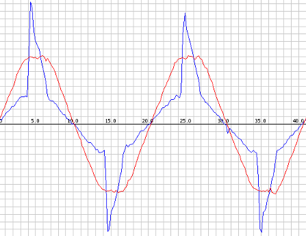
If your load looks like the blue graph (reactive load, taken from the link in my previous post) you have to integrate the surface area to get the true RMS value (that's why true RMS multimeters are in general more expensive and are advertised as such). I think the emon lib does exactly that, but I would have to check.
As a test you could run a sketch which samples the voltage from the ACS712 as fast as possible and outputs these values to the serial port. Recent Arduino versions contain a 'serial plotter' which then graphically show the power usage.
A test sketch could be as simple as:void setup() { Serial.begin(115200); } void loop() { Serial.println( analogRead(A0) ); }Flash it, select serial plotter in the tools menu and watch the output.
http://yveaux.blogspot.nl
-
@Sushukka The getVPP function samples for 1 second and returns the maximum peak-peak voltage of these samples.
For purely resistive loads it is correct to multiply this peak-peak voltage by 0.707 to get the RMS value.If your load looks like the blue graph (reactive load, taken from the link in my previous post) you have to integrate the surface area to get the true RMS value (that's why true RMS multimeters are in general more expensive and are advertised as such). I think the emon lib does exactly that, but I would have to check.
As a test you could run a sketch which samples the voltage from the ACS712 as fast as possible and outputs these values to the serial port. Recent Arduino versions contain a 'serial plotter' which then graphically show the power usage.
A test sketch could be as simple as:void setup() { Serial.begin(115200); } void loop() { Serial.println( analogRead(A0) ); }Flash it, select serial plotter in the tools menu and watch the output.
@Yveaux said in ACS712 strange values when measuring 3D printer power consumption:
void setup() {
Serial.begin(115200);
}void loop() {
Serial.println( analogRead(A0) );
}Cool, haven't thought you could use plotter like this. Hair dryer gave pretty sin/cos like load, Kossel 3D printer with a normal computer supply is quite close but Prusa's load was pretty spiky. It looked like:
                /|
               / |
              |   \
      /------/    |
----/             \----
Which probably underlines pretty well your point. :) Question is that is there anyway to tackle this when using emonlib?
-
@Yveaux said in ACS712 strange values when measuring 3D printer power consumption:
void setup() {
Serial.begin(115200);
}void loop() {
Serial.println( analogRead(A0) );
}Cool, haven't thought you could use plotter like this. Hair dryer gave pretty sin/cos like load, Kossel 3D printer with a normal computer supply is quite close but Prusa's load was pretty spiky. It looked like:
                /|
               / |
              |   \
      /------/    |
----/             \----
Which probably underlines pretty well your point. :) Question is that is there anyway to tackle this when using emonlib?
@Sushukka said in ACS712 strange values when measuring 3D printer power consumption:
                /|
               / |
              |   \
      /------/    |
----/             \----
Cool ASCII-art :+1: Next time you could just attach a screenshot :hatched_chick:
I had a quick look at emonlib and it appears to measure the true RMS value; it takes a number of samples and sums the squared values: https://github.com/openenergymonitor/EmonLib/blob/master/EmonLib.cpp#L187
It is designed for specific hardware and applies some correction that might not match your sensor.
On the other hand, if your other (resistive) loads match the reference power meter the algorithm seems to work ;-)Did you consider that your power meter could be off for reactive loads? :confused:
http://yveaux.blogspot.nl
-
@Sushukka said in ACS712 strange values when measuring 3D printer power consumption:
                /|
               / |
              |   \
      /------/    |
----/             \----
Cool ASCII-art :+1: Next time you could just attach a screenshot :hatched_chick:
I had a quick look at emonlib and it appears to measure the true RMS value; it takes a number of samples and sums the squared values: https://github.com/openenergymonitor/EmonLib/blob/master/EmonLib.cpp#L187
It is designed for specific hardware and applies some correction that might not match your sensor.
On the other hand, if your other (resistive) loads match the reference power meter the algorithm seems to work ;-)Did you consider that your power meter could be off for reactive loads? :confused:
@Yveaux ASCII art + SID music ftw. :) I played around with the sampling time (changed from 1480 to 3000/6000):
double Irms = emon1.calcIrms(6000)Now the values are pretty close together. Still had to manually do the zero load subtraction (around 30W) but after that ACS712 shows surprisingly accurate values even for low 10/20W loads. Now it seems that when Prusa is heating up I get constantly around 100W higher values than I should. But when I turn the Kossel or hair dryer on = adding load to the same line, the Prusa crap seems to fitted in (or filled in) so that the total load seems to be accurate. My "reference" power meter could be off for reactive loads, but not this much and moreover Prusa's power supply is around 200W and I get 300W readings from ACS712.
Anyway, I think I'll take the "so be it" step now and just have to live with the fact that Prusa will skew my power readings a bit. Usually there will be some other load in the same line so it should be partly corrected by that. Your help @Yveaux was pretty useful and I thank you for that. :) Also I usually have trusted to some homemade power calculation algorithms because OpenEnergyMonitor is so heavily based on CT3 but as I now saw how much better accuracy its algorithms give I'm going to switch in to that in future projects.
-
I have only one line going through ACS712 and then its splitted to multiple outlets with extension cord. First I though that my 20A ACS712 is actually only 5A one, but same problem happes with the second ACS712 20A. Also even 5A should be able to measure this load as Prusa's maximum intake is around 180W.
Maybe it has something to do with the power factor, dunno. Now I have anyway managed to pinpoint the problem to 3D printers. When plugging only Arduino+ACS712+Prusa MK2 to the wall, ACS712 shows around 690W loads when the Prusa's maximum is about 180W as mentioned above. My old faithful hair dryer power consumption is measured correctly (430W, 820W, 1400W).@Sushukka thanks for sharing!
Hello! It looks like you're interested in this conversation, but you don't have an account yet.
Getting fed up of having to scroll through the same posts each visit? When you register for an account, you'll always come back to exactly where you were before, and choose to be notified of new replies (either via email, or push notification). You'll also be able to save bookmarks and upvote posts to show your appreciation to other community members.
With your input, this post could be even better 💗
Register Login