What did you build today (Pictures) ?


  • @Yveaux said in What did you build today (Pictures) ?:

    @bjacobse said in What did you build today (Pictures) ?:

    @Yveaux
    I think I have similar washing machine, doesn't the LED blink if leave the laundry inside the machine after it had ended washing?

    The sensor is placed on a led that lights when the machine is finished. I would prefer a led that is lit when it is washing and goes out when finished, but my machine hasn't any.

    Just curious, if you anyway have had the lid/cover removed from washing machine, why not solder wires parallel to LED and connect to an optocoupler that feeds signal direct to Arduino, and also take 5V supply from the washing machine, and then you can avoid using batteries

    Now I simply removed the cover to hide the wire. The electronics and led are hidden behind a lot of metal aan plastic. I didn't want to take the washer apart and the dryer too.

    Just a simple solution working for multiple devices.

    Ah this make good sense, I didn't think the electronics was hidden and difficult to get to


  • Mod

    @bjacobse said in What did you build today (Pictures) ?:

    Ah this make good sense, I didn't think the electronics was hidden and difficult to get to

    It's German quality 😏


  • Finally got my LoRaWAN RAk831 with RPI gateway online


  • @Yveaux So I never fully understood the reasoning behind putting sensors on a washer or dryer. So you start your clothes washing or drying before you leave for somewhere. Is there a reason to know that it's finished when you are away? There is nothing you can do about it until you get home, at which time you could reasonably assume that it is finished. If you are home, can't you just go and check it after some time? Why would you need a message on your phone?

    Just curious.


  • Mod

    @dbemowsk just to keep the machines running continuously πŸ˜‰
    And I need to go up 3 stairs to just check on them πŸ’©


  • @Yveaux Makes some sense. Another reason would probably be....."Because you can"... LOL


  • Hardware Contributor

    @dbemowsk said in What did you build today (Pictures) ?:

    @Yveaux So I never fully understood the reasoning behind putting sensors on a washer or dryer. So you start your clothes washing or drying before you leave for somewhere. Is there a reason to know that it's finished when you are away? There is nothing you can do about it until you get home, at which time you could reasonably assume that it is finished. If you are home, can't you just go and check it after some time? Why would you need a message on your phone?

    Just curious.

    Or if someone else than you starts the machine before leaving for the full day, and you come back much earlier and if you don't have a warning you don't necessarily think about checking the washing machine when you arrive home. Here with the warm temperature if I leave the laundry in the washing machine for 4-5 hours without opening, I'm good for a new wash because it will smell pretty bad 😞


  • @dbemowsk
    My wife actually fairly often forget to check when the washingmachine is finished, and notice it a few hours later, when kids are a sleep and there is quiet in the house, I will imagine receiving an SMS when washing machine is ready to be emptied will help her, as she is checking her phone often,, even when kids are using all her time


  • Hero Member

    The value on a dryer is even more tangible: the sooner you get your clothes out, the less wrinkly they get.


  • @NeverDie All good points that I hadn't thought of.


  • MySensors Evangelist

    @dbemowsk while you are at it..consider πŸ™‚

    The dishwasher can be added as well. My devices dishwasher / washing machine / dryer send messages to all tvs that are turned on. Identifying themselves and invite you to come and clean them :). It comes in handy and absolutely jaw dropping on your visitors.

    If you turn on the stove air circulation system in the kitchen... Why not greet the wife with automatically start the TV in the kitchen and play her favourite radio channel at her preferred volume...


  • Hero Member

    Back to the OP topic, I made a micro-usb OTG cable (bottom cable below) that passes through all 5 pins:
    0_1511722883854_OTGcable.jpg
    This will replace the more fragile cable above it in the next generation of my nRF5 micro-usb programming/debug adapter.

    It turns out you can't buy this cable. At least, I couldn't find any for sale. Instead, I had to make it myself. Fortunately, Adafruit sells a little DIY kit that helped tremendously:
    https://www.adafruit.com/product/1826

    πŸ™‚


  • Mod

    @NeverDie So much heat shrink tubing -- makes my eyes hurt 😭


  • @NeverDie So many colours of nations offended... Have you thought of going for President ?


  • Hero Member

    Actually, this was the very first time I've used shrink tubing. How could I do it better?

    Mostly I didn't want there to be much bending, which might lead to tearing loose the solder connections. I wanted the finished cable to be a "once and done." Now that it's done, the connections should go very easy.


  • 0_1511727705490_15117276954701212117694.jpg

    0_1511727729141_15117277179511389767526.jpg

    I use raspberry for watching television, movies etc. Today I build raspberry hat to turn on from remote control. Attiny85 recognizes programmed remote code and by optocoupler short circuit on pins.


  • @scalpel how do You program the ir code for the power button ? can it be programed from the linux running in the rpi ? or it is just hardcoded into atiny code ?


  • Hardcoded In attiny. Learn arduino irremote library.

    Pozdrawiam / regards


  • @scalpel yeah, I did this kind of project also and I wonder if there is a software for that πŸ™‚ It would be fun to be able to set the wakeup ir code from the linux os, with for example i2c or 1-wire interface.


  • Mod

    @rozpruwacz how often would you need to change the IR code for that?


  • rarely, but still it would be fun to make such thing πŸ™‚


  • @sincze said in What did you build today (Pictures) ?:

    her favourite radio channel at her prefer

    @sincze hi, could you elaborate a bit more the TV messages, do you have any link with more info? Was that the LG tv with Mqtt that was mentioned on the forum?(or I mixed forums)


  • MySensors Evangelist

    @dakipro we use kodi on al lgl tvs. The libreelec TV box has cec and can turn on the TV via hdmi. If TV is on I am able to control the volume via the LG webserver. Kodi (api) can display the notifications for Me :). Not that fancy but it works like a charm.


  • Side note. I did a quick search, there is a cec library for arduino!
    https://github.com/stefslon/cec-arduino


  • @sincze
    If it works like a charm - it's fancy πŸ˜‰


  • Hardware Contributor

    Back to topic! Last night I made some changes to my ATX Power supply because the variable settings was to sensitive:

    0_1511953574080_upload-c7feca62-d22d-435e-9c73-9599ca0c9044

    0_1511953586756_upload-3bb65a38-91b8-4dc8-9dd7-3a0af6fd45f9


  • @sundberg84 Did you find that taking the cover off improved the accuracy at all ?
    πŸ˜†


  • I built a lithophane lamp for my grandson. The electronics is basically only a pro mini and 36 neopixels. Sadly this version is not mysensorized but maybe I'll do that in version 2 πŸ™‚

    0_1511962986127_IMG_8296.jpg
    0_1511963011727_IMG_8301.jpg
    0_1511963026597_IMG_8297.jpg
    0_1511963045498_IMG_8298.jpg


  • Hero Member

    @maghac Cool. How were you able to convert the photos into that embossed material (or whatever it is)? Is that a CNC process, or something else? It seems to have very good resolution.


  • Mod

    I have seen a video where you can convert your pictures and print them using a 3D printer


  • @gohan said in What did you build today (Pictures) ?:

    I have seen a video where you can convert your pictures and print them using a 3D printer

    Correct, these are 3D printed lithophanes (https://en.wikipedia.org/wiki/Lithophane). I used http://3dp.rocks/lithophane/ to convert jpg files to STL files for printing.


  • Hardware Contributor

    After failing to assemble a completely functional version of my new livolo switch board, I assembled a first prototype of my new "22" sensor board. Unfortunately I didn't receive the sensors yet so it only has a switch, a hall sensor for door and a led, but that's enough for the first testing.
    Board is made to cut headers when it will be finished, but meanwhile I can use the headers to make it a breakout board for the nrf51 module or for each of the sensors.
    0_1512127797656_22.jpg


  • Hardware Contributor

    @Nca78 nice πŸ‘ it looks like familiar to me, i don't know why πŸ˜‰ I agree with you, I prefer rounded square shape as it fits more easily everywhere than circles


  • Hero Member

    πŸ‘ Have you settled yet on what kind of connector you're going to use on future boards?


  • Hardware Contributor

    @scalz said in What did you build today (Pictures) ?:

    @Nca78 nice πŸ‘ it looks like familiar to me, i don't know why πŸ˜‰

    Not sure which one you're talking about, as it's some kind of child between @NeverDie 's board (same nrf51 module and small size) and your aeos (shape, on board sensors). But it's more like a challenge to me, make the smallest board possible (22*22mm) with as many sensors as possible (at the moment, door, TH, light, accelerometer) and I have a bit of margin to add more like the leak detection from @NeverDie it's really nice to be able to do it with such a tiny sensor.
    I'll do a more complete and flexible 33 board later, I will try to make it some kind of a hand-solderable version of aeos πŸ˜‰


  • Hero Member

    As far as minimizing size goes, I think you're right: square (or some kind of rectangle) is going to be better. I end up throwing away a lot of useable space going from square to circle, which, unfortunately, forced me into increasing the diameter (i.e. the size). So, in the end, square/rectangular is probably better. πŸ™‚ I think the allure of the circle is to try to fit the whole thing perfectly onto a coincell (which acts as a kind of limit on how small you can ultimately go), but unfortunately that can't happen with any of the coincell holders I've seen so far....


  • Hardware Contributor

    @Nca78
    It was just a private joke πŸ™‚ If I inspire some people, then I'm glad! Because like you said, aeos is different (better mcu, more ios&sensors, and latest unpublished revision is..more generous).

    But, if you're trying to make a "aeos" (same sensors for instance) in future, then i don't get the point..why reinventing the wheel? Your board has qfn/dfn footprints too, so I don't see how it's easier to handsolder.
    If this is related to Ic's price, there are lot of different ways to get them cheaper.

    You should maybe use stencils (maybe you already do it) that will save your day πŸ˜‰

    Keep the good work

    @NeverDie yep, agree with you


  • Hero Member

    @scalz We're not going to get much software being written (such as, for instance, an OTA booloader that we can all use or cool self-destructing crypto wizardy) until there's worthwhile nRF5 hardware available, so anything you can do to speed up the release of your designs would really help. I've been trying to Johnny Appleseed this, without getting much apparent traction on people adopting it. People seem to like your stuff, which looks very professional. If you can, try to make it available so people can start writing software, integrating it, etc. As the saying goes, a rising tide lifts all boats. πŸ™‚


  • Mod

    @NeverDie said in What did you build today (Pictures) ?:

    I've been trying to Johnny Appleseed this,

    What have you been trying to do? πŸ˜…


  • Hero Member

    @gohan said in What did you build today (Pictures) ?:

    @NeverDie said in What did you build today (Pictures) ?:

    I've been trying to Johnny Appleseed this,

    What have you been trying to do? πŸ˜…

    I posted a lot of nRF5 PCB's hoping that others would find some appealing and jump on the nRF5 bandwagon, but so far not much seems to have happened. Aside from some helpful feedback/suggestions from @nca78, I'm not really any better off than if I hadn't bothered. I'm not sure what motivates other PCB posters, but the feedback/suggestions have been the only real payoff for me. Unfortunately, most PCB postings have garnered zero, even if there appear to have been a lot of downloads.


  • Mod

    @NeverDie @scalz To get the nRF5 series adopted by MySensors and its users I think we should start with a single board. We have to make sure it is easy to obtain/replicate (by using a ready available module, or using a hardware partner where people can just order the board) and supply the required getting started docs.
    I really appreciate all the work done on the nRF5 support, but now we have to take the leap from prototype to 'production' to get it adopted by the community.


  • Mod

    @Yveaux agreed
    @NeverDie don't let you down, not everybody knows how to design PCBs or provide suggestions in that matter.


  • Hero Member

    @Yveaux said in What did you build today (Pictures) ?:

    @NeverDie @scalz To get the nRF5 series adopted by MySensors and its users I think we should start with a single board.

    I think that's a good idea. A standardized reference platform would really help in building some forward momentum. How about you start a thread saying exactly what it is that you'd want the board to be like, and maybe it will gather some consensus and someone will make it. Like I say, I've launched numerous trial balloons, and it's just not an efficient way to get there from here. My guess is it will be some kind of multi-sensor board, maybe even the same as what @scalz and/or @nca78 are already doing.


  • Hardware Contributor

    @scalz said in What did you build today (Pictures) ?:

    @Nca78
    But, if you're trying to make a "aeos" (same sensors for instance) in future, then i don't get the point..why reinventing the wheel? Your board has qfn/dfn footprints too, so I don't see how it's easier to handsolder.

    Bigger board won't have those QFN and LGA footprints of course πŸ˜‰
    As you say I don't want to reinvent the wheel, especially one that'll look square compared to yours πŸ˜„
    But I think it's important we still have a DIY option available for those who don't like soldering LGA or 0402, an equivalent of using the pro mini for the nrf5 world.


  • MySensors Evangelist

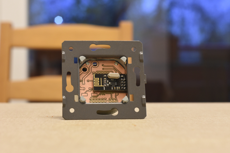
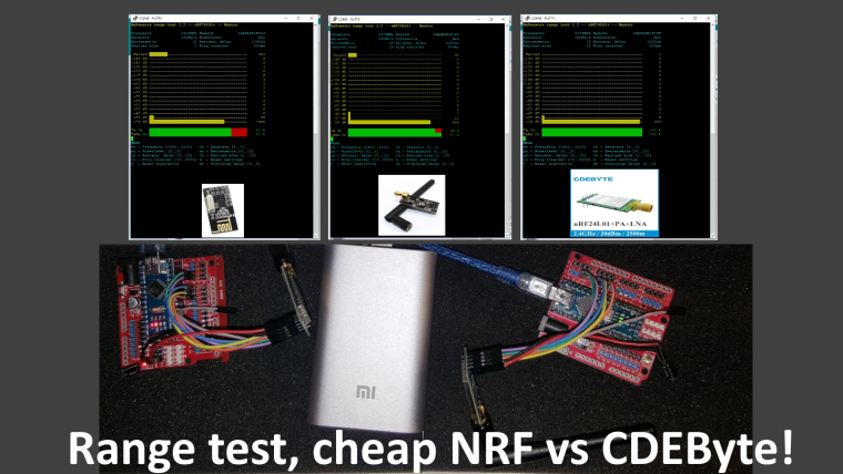
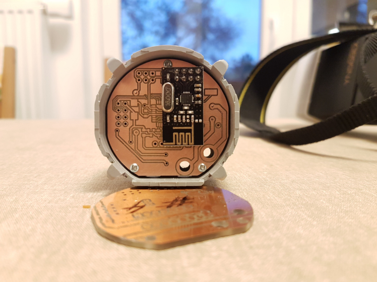
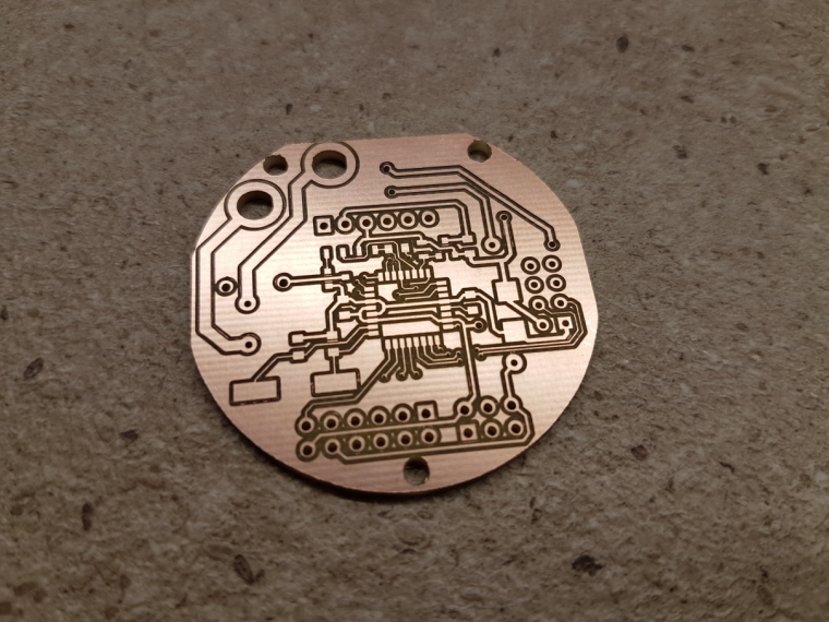
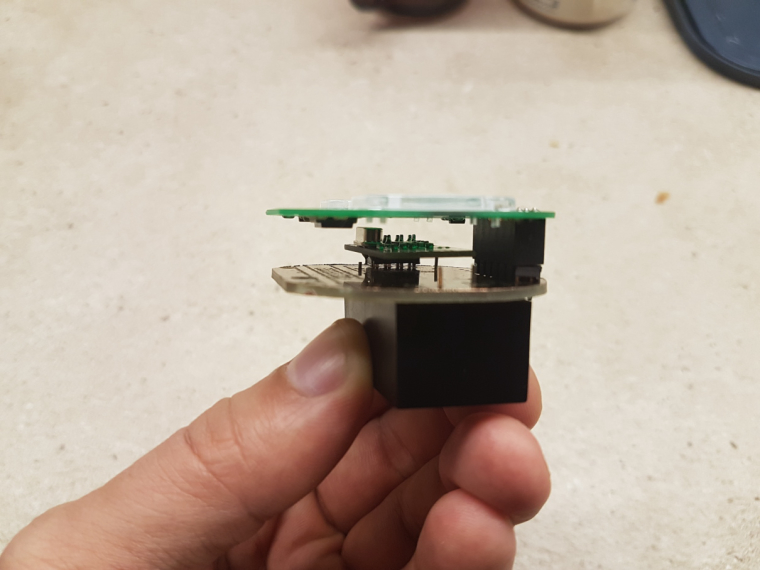
    This sunday a friend of mine and I did not know what to build. So we decided to use a project designed by @Yveaux
    Source

    I received 2 new CDEByte antennas that needed a range test. As I live in a mansion.... Next to a park we figured out that walking 1 degrees outside would be an excellent time to do a range test. It was not raining so.....

    Our conclusion would be:

    • Cheap ass NRF... good enough for indoor usage.. if it can mesh.
    • Cheap ass Amplified NRF.. good enough in the house, needs a bit more space and power, but works quite well.
    • CDEByte... not cheap.. but man my hands were freezing outside due to the long range.. And according to @Yveaux we could achieve a higher range if we would have set the power to MAX... During testing this was MIN.

    0_1512323585357_cdebytetest.jpg


  • @sincze said in What did you build today (Pictures) ?:

    CDEByte

    Thank you for the test πŸ™‚ Which pointed to me that I urgently need a new serialgateway and use CDEBYTE


  • Over the weekend I hacked the previously battery powered Minecraft lights in the Minecraft bedroom (doesn't everyone have one?). Now there's no more replacing batteries and OpenHAB controls include On, Off, Brightness and Flame Flicker.

    This is the reason I was asking about establishing power distribution in the attic. I've decided to distribute 12v and drop to 5 or 3.3 only as needed.

    More info and video: https://techconz.com/smart-home/minecraft-lights/

    alt text
    alt text


  • Hero Member

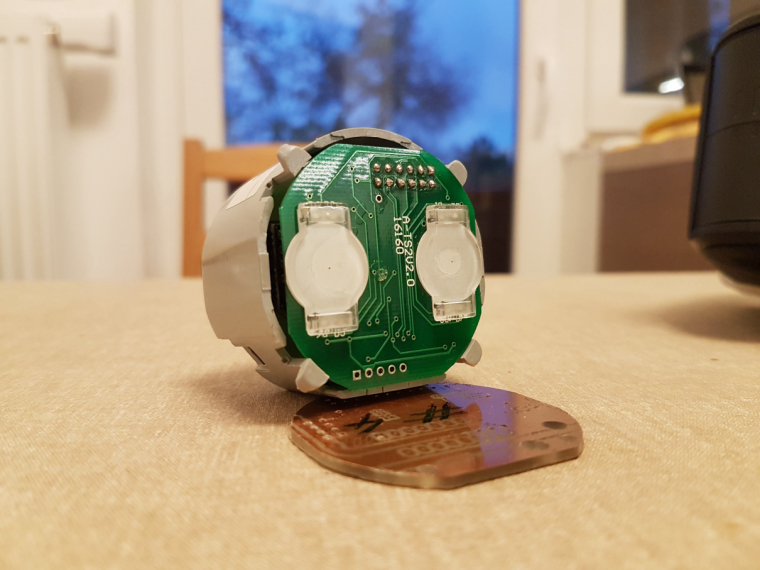
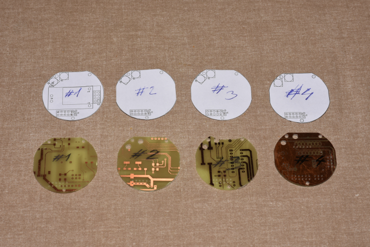
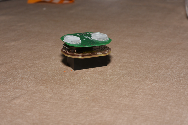
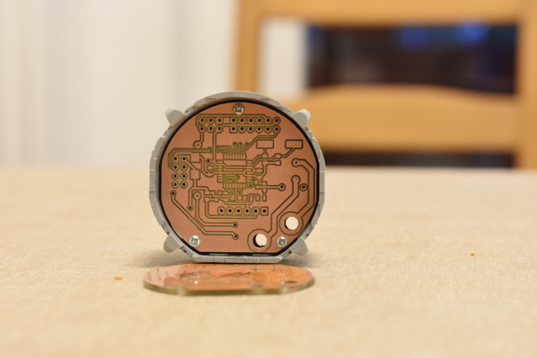
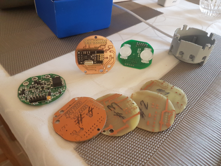
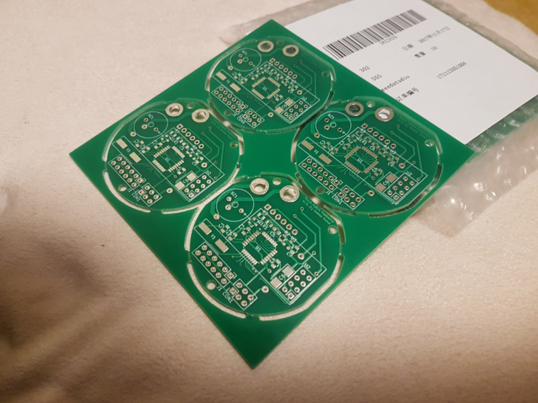
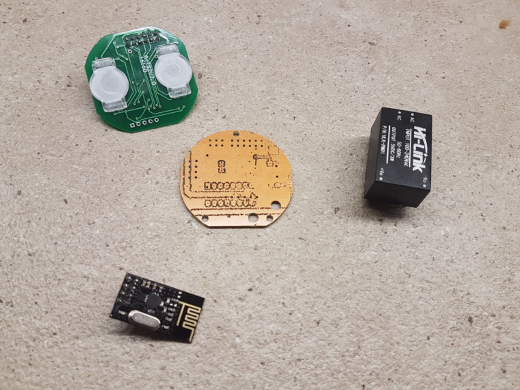
    Received the PCB today, so I put together this leak detector for testing:
    0_1512430579892_leak1.jpg
    0_1512430601719_leak2.jpg
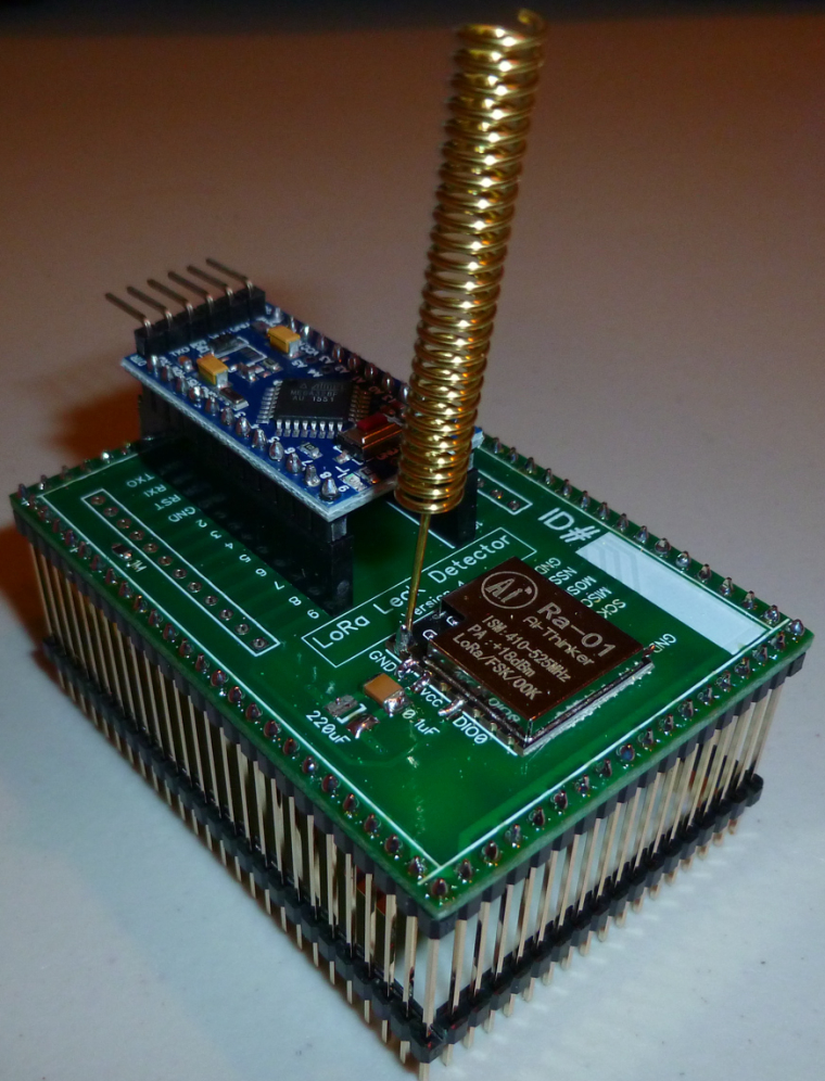
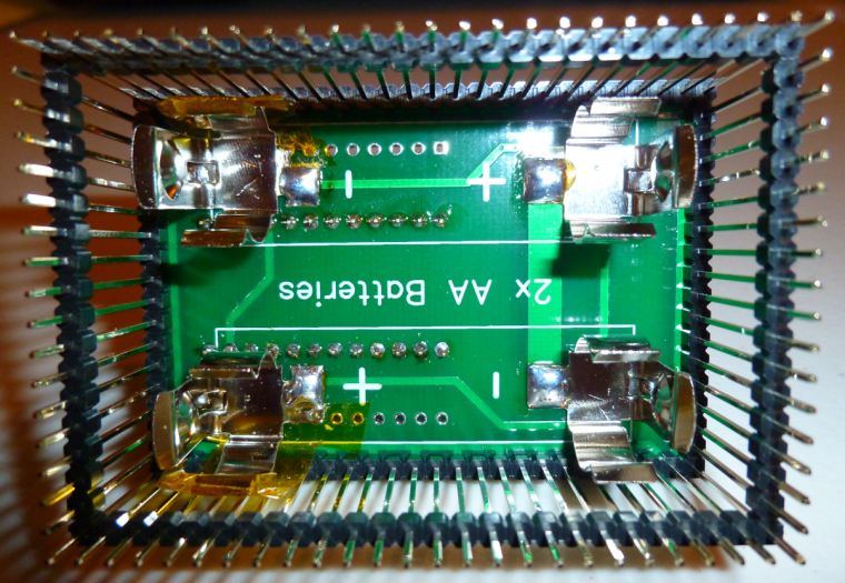
    Looks as though some of the physical clearance tolerances are a bit tight, so I'll have to do another spin after changing the PCB layout. Some Kapton tape will compensate for now and allow for some initial testing.


  • Not MySensors, but related. Power over Ethernet (802.3af compliant) addon for the raspberry pi zero. I plan to use this for high power & high reliability devices where wireless will not work.

    Top one is a higher power version, bottom one just uses an off the shelf regulator.
    0_1512445820284_2017-12-04 19.44.55.jpg

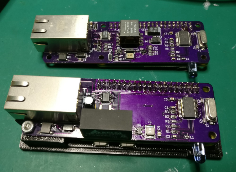
    Currently these just have some IR LED's to control IR devices.


  • Hero Member

    @SquareKinematics
    Very useful to have. Not sure if you're aware, but you can buy PoE power adapters off the shelf. Even Amazon sells them. You select the output voltage you want with a slide switch.


  • MySensors Evangelist

    And so it it almost Christmas...

    Jolly jolly.. wel actually no....

    We have had wet feet from the central heating system serveral times now around Christmas or New Year.
    Causing a wet floor and other possible disasters. Yes I know.. A Central Heating Mechanism should not leak, you could try putting a bucket underneath... But that is not 'that home automation' smart that I was looking for.

    So to detect a leakage.... I came up with this some time ago.

    Pretty standard, a few wires... a Mysensors Node... and Pushover to send me urgens notifications about the leakge.
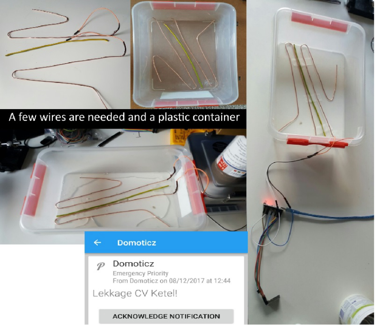
    0_1512750844649_Leakage.jpg link url))

    And ladies and gentlemen it actually works as you can see in the pushover sreenshot, it kicked off today.


  • Hero Member

    @sincze You could also put some salt into your tray for added conductivity when things get wet.


  • MySensors Evangelist

    @neverdie Great tip, this will resolve in even a quicker response during a flood right?. I already added toilet paper as cover for a smooth moist/water distribution. Lets add some salt to that and hopefully never see an error message again. But I wont bet a bitcoin on that ;-).. Happy with this cheap solution.


  • Mod

    well, since you are not using distilled water, normal tap water should have enough conductivity


  • @sincze How did you design the detection circuitry? Are you using an analog or a digital input?

    Tap water should work without adding more conductivity - in my case I just designed something similar but I wanted to detect an overfill of osmosis water, which is similar to distilled. I had issues with getting it to work through a digital input, so I just built a voltage divider capable of detecting the small change in conductivity. I also added a capacitor to be sure that no false alarms would be received because of noise in the lines. It's been working perfect for days now.


  • @neverdie said in What did you build today (Pictures) ?:

    @sincze You could also put some salt into your tray for added conductivity when things get wet.

    Be very careful using salt,i killed an SI7021 doing something similar.
    I got up one morning and found the sensor covered in white fur and it was dead☹


  • 2 gang EU type livolo customisation, from theory to product... still in progress.

    2_1512829925723_small_20171112_011444.jpg 1_1512829925723_small_20171101_175752.jpg 0_1512829925722_small_20170114_124152.jpg 2_1512829936757_small_20171119_155004.jpg 1_1512829936757_small_20171118_202738.jpg 0_1512829936757_small_20171112_011725.jpg !


  • 0_1512830079874_small_20171119_155404.jpg 0_1512830092134_small_20171119_163354.jpg 0_1512830107562_small_20171119_163849.jpg 0_1512830119867_small_20171119_164745.jpg 0_1512830130032_small_20171119_165717.jpg 0_1512830150237_small_20171203_092353.jpg 0_1512830159490_small_20171203_163658.jpg 0_1512830169403_small_20171207_194213.jpg


  • Hero Member

    @andrew Wow!


  • MySensors Evangelist

    @manutremo As the water indeed is 'rock' solid here in the area I was pretty succesfull using the digital pins. A short... when there is a water connection or open... when there is no connection. No false alarms. Only legit... Each leakage costs me money to get some guy to fix it for me. But at least the floor is not ruined anymore as I had that the first 2 times.


  • MySensors Evangelist

    @rmtucker ai ai . what happened with the salt???


  • MySensors Evangelist

    @andrew Wow indeed.


  • MySensors Evangelist

    Almost Christmas, that means... Lights. In this case programmable 5v LED's that are driven by an Arduino and controlled via Mysensors & Domoticz.

    0_1512836207823_WhatsApp Image 2017-12-09 at 17.14.55.jpeg

    While the arduino sketch has a lot of tricks (showing animations).. I still have to figure out HOW I can stop an animation from playing when I want to see the next one.. It now completes the first animation.. and then starts the one I selected. It needs to break from the function if a new message comes in. I'll have to look for some examples in the forum.


  • @andrew I see that You put the nrf module between two pcbs. Do You have issues with reception ? Because the boards may act as a shielding.


  • @rozpruwacz I try to avoid filled copper areas, which could act as RF blockers. as I mentioned, everything is still in progress, in-wall tests will just come. hopefully I'll have time for that in the next 2 weeks.


  • Mod

    (CNC milling forked to separate thread. It got too interesting πŸ™‚ )


  • Hardware Contributor

    @andrew

    I know that this is not the right place to ask but I'm very curious how do you overcome the fact that in EU there's only the live with in the walls for light switches. I saw that you used a HLK-PM0xx module for testing which needs both live and null. Or maybe your "in-wall" wiring is different... Anyways congratulations for your work so far.


  • @mtiutiu well, that's the dirty hacking part πŸ™‚ electricians will probably not like it.

    so, for first, I've a different approach to control my lamps compared to other in-wall switches and dimmers, due to the fact, that I won't switch the mains directly, with the switch. I have LED ceiling lamps which operate at 12V, but the power supplies (230V to 12V) are in the lamps' body. it could be possible to switch their mains on/off thus to turn the lamps on/off (this is what I do now with standard switches), but it is not possible to dim the lights this way.
    to be able to dim the LEDs as well I'll have a lamp controller node right after the switching PSUs in each lamp. this will be controlled with the in-wall switches (and could be controlled with other nodes/gateways as well), over the air only.

    as all of my wall lamp switch have dual wiring (one line in, two switched line out) I planned the following setup:
    one switched line will be "re-assigned" and wired to N at the lamp. this way, at the wall switch I'll have both L and N. the other switched in-wall line will still forward the L to the lamp, but it will do it directly, to continuously operate the lamp's PSU, which also powers the lamp's controller module.
    the controller will be always on and it will control both the dimming (PWM on the 12V) and the switching wich basically allowing or disabling the 12V from the PSU to the LEDs.

    the in-wall switch will be basically just a radio remote controller this way, but operating from the mains, without any need of batteries.

    I hope that my explanation wasn't too complicated πŸ™‚


  • well today finally i decide to change to c.h.i.p. as a controller with domoticz an amazing device but too bad for the product that got really bad customer support, ( if you planning to buy a c.h.i.p. read the forum first to get all the problems)

    this is my controller using a chip, arduino nano

    0_1512877583590_IMG_20171209_213652.jpg
    0_1512877592331_IMG_20171209_213710.jpg

    planing to chage the nano to a nodemcu


  • Hero Member

    @fernando-alvarez-buylla Is the C.H.I.P. better than a Raspberry Pi Zero? At least with a Pi, you know there's going to be support.
    https://www.adafruit.com/product/2885?gclid=EAIaIQobChMIrMm-lcv-1wIVxSSBCh1PJQB3EAQYASABEgItsvD_BwE
    https://www.adafruit.com/product/3400


  • @neverdie go for the pi zero chip is really nice a little better than the pi zero wifi and bt integraded 4gb and a few cool stuff , but theres people that pay a year ago and still waiting for the chip to arrive , no reply and no support on forum , to me chip is dying , you cant never go wrong with a pi , but i will try in a few months the omega2 to remplace my chips


  • Hardware Contributor

    @fernando-alvarez-buylla said in What did you build today (Pictures) ?:

    i will try in a few months the omega2 to remplace my chips

    What kind of controller are you going to run on that underpowered thing ? Entry level price is cheap but if you want SD card reader and a bit more storage (32Mb) you have to pay 20$, more than the price of an orange pi zero + box which is already available and runs well with Armbian.


  • Hardware Contributor

    Working on clearing up the backlog of unfinished NModule shields, today I finished to test the dual touch button shield, made a script to use it as on/off button or as dual button with short press = on and long press = off, as seen below as a dual scene controller.
    https://www.youtube.com/watch?v=064Jlx2eawI

    I made a box so it can be easily customized depending on what you use it for. Unfortunately internet is too bad at the moment in Vietnam to use Fusion 360 so I made it with 123D Design which is less convenient and it's not really high-end assembly πŸ˜„

    0_1512964810931_IMAG2085.jpg
    0_1512964835281_IMAG2084.jpg


  • Hero Member

    @nca78 said in What did you build today (Pictures) ?:

    I made a box so it can be easily customized depending on what you use it for.

    Is it a 3D printed enclosure then, or did you find some other way to make it? Looks very nice.


  • Hardware Contributor

    @neverdie said in What did you build today (Pictures) ?:

    @nca78 said in What did you build today (Pictures) ?:

    I made a box so it can be easily customized depending on what you use it for.

    Is it a 3D printed enclosure then, or did you find some other way to make it? Looks very nice.

    3D printed. Bottom of prints can look pretty good if find the good settings and print on a glass surface.


  • @nca78 I would assume that pads 1 and 2 are capacitive touch surfaces, correct? very nice design.


  • Hardware Contributor

    @dbemowsk said in What did you build today (Pictures) ?:

    @nca78 I would assume that pads 1 and 2 are capacitive touch surfaces, correct? very nice design.

    Thank you !
    Yes using dirt cheap TTP223 breakouts at the back so no SMD soldering needed.


  • Hero Member

    I received the next version of the leak detector PCB today. Putting it together, it checks out: thanks to a change in layout, it has the same board size as before, but now no clearance issues. i.e. No need for Kapton tape!
    0_1513028902071_leak_v6.jpg
    If I had had my own PCB CNC etcher, it would have saved me the time I lost waiting for the earlier version from the fab, only to find out that the clearances were too tight and that I would have to re-do it. Looking forward to not having such delays ever again.


  • Christmas wreathe for the techie in all of us.
    pretty colors
    flashing
    wire wrapping

    Uses a pro mini and a lot of wire-wrapping. Other components on the circuit boards are just there for show.

    (ugh, google photos links not showing up so converted to links)


  • @wergeld Hadn't thought of it that way... Good call....


  • Hardware Contributor

    Finally got the PCBs from AllPCB.com (cost 5 Euros and took a total of 7 days from order submission to free DHL delivery to Europe!!!) for my own MySensors Arduino Pro Mini prototyping board. Unfortunately the soldering iron broke during my assembly, so it's not fully finished and I couldn't test it yet, either...
    Arduino Pro Mini IO shield
    Arduino Pro Mini IO shield

    This board is inspired by the Nano IO shields that are offered on AliExpress and improves it further for my needs (and switched to the Pro Mini instead of the Nano).

    • Each analog and digital pin of the Pro Mini has its own VCC and GND pins,
    • the board also provides its own voltage regulator, solder pins for by NRF24L01+ and RFM69H are provided (plus the 5V->3.3V XC6206 regulator),
    • either a tiny 55-pin breadboard or three IΒ²C connectors can be placed on the board.
    • One can also use PogoPins instead of soldering the Pro Mini (or headers for it) to burn the bootloader or change fuses on the Pro Mini via the ICSP connector.
      Using PogoPins to burn the bootloader

    All design files are available on GitHub: https://www.openhardware.io/view/538/Arduino-Pro-Mini-IO-Shield


  • Hero Member

    @reinhold I like how you hid the pin holes for the ICSP underneath the breadboard.


  • Mod

    A temperature controlled PWM fan controller for my DPS5005 power supply!

    0_1513282712833_b39ad537-771a-4175-bb65-07a980b2b734-image.png

    The original 2-wire fan that came with the power supply casing made an incredible amount of noise.
    Using PWM to reduce its velocity made it even more noisy πŸ‘Ώ

    So, I made a fresh start and ordered a quality fan (almost as expensive as the whole casing...)

    Using nothing more than a 5V pro mini, piezo speaker, DS18B20 temperature sensor and a resistor I made a full fledged fan controller πŸ˜‰

    It takes the current temp from the DS18B20 (which will be mounted on the heatsink) and ramps up the fan linearly in the 30..60 C range. Below 30 C, the fan is off.
    If RPM readback indicates a stalled fan, or DS18B20 returns wrong values the buzzer will force me to invest what's wrong πŸ’ͺ


  • Mod

    @yveaux next step is to use the piezo for active noise cancelling πŸ˜‰


  • Mod

    @mfalkvidd don't tempt me...


  • Mod

    @yveaux that looks like a Noctua fan. I have a DPS5015 and I was planning to make some mods on the case (I got the other model that is bigger), so I guess I am gonna ask you for some code πŸ˜„


  • Hardware Contributor

    @yveaux said in What did you build today (Pictures) ?:

    The original 2-wire fan that came with the power supply casing made an incredible amount of noise.
    Using PWM to reduce its velocity made it even more noisy πŸ‘Ώ

    Less funny that way but did you try to lower the PWM frequency of the atmega to it's minimum ? I had the same problem with the fan I put in my fridge cabinet and low PWM frequency solved it.


  • Mod

    @nca78 I did fiddle with the frequency, but the fan was just total crap, so I decided to replace it anyhow.


  • Admin

    @Yveaux @Nca78

    An RC filter could probably also make wonders for the fan. I had to add one for the parts fan on my 3D printer. Couldn't control the speed with PWM without the RC filter..

    Btw. probably a bit over the top of using an arduino as fan control? Unless you plan on adding a NRF radio, and report the temperature + PWM duty cycle to your mysensors system, and store the values in influxdb? πŸ˜‰


  • Hero Member

    @tbowmo said in What did you build today (Pictures) ?:

    Btw. probably a bit over the top of using an arduino as fan control?

    Really? How so? Seems like the end result will be as quiet as possible, yet avoids stalling.


  • Mod

    @neverdie said in What did you build today (Pictures) ?:

    @tbowmo said in What did you build today (Pictures) ?:

    Btw. probably a bit over the top of using an arduino as fan control?

    Really? How so? Seems like the end result will be as quiet as possible, yet avoids stalling.

    Indeed! I thought of going the analog way, but the final solution would be more expensive, I didn't have the parts at hand, it wouldn't have as many features and it would have cost me a lot more time...


  • Mod

    @tbowmo said in What did you build today (Pictures) ?:

    An RC filter could probably also make wonders for the fan.

    Probably, but again, the fan was total crap and made a lot of wind noise due to the bad condition of its blades.


  • Admin

    a 555 and a couple of resistors / capacitors.. πŸ˜‰

    https://electronics.stackexchange.com/questions/91102/555-temperature-controlled-pwm

    But then again, I recon that most of us might have more atmega328 based boards, than 555's in the parts bin πŸ™‚

    about the RC for PWM, it was meant as a hint for others that might fight problems with a fan that they couldn't control properly with PWM..


  • @tbowmo 555s need knowledge... i wouldn't know what to do with these πŸ˜• except cufflinks
    arduinos are much more accessible πŸ˜‰


  • Mod

    @tbowmo said in What did you build today (Pictures) ?:

    a 555 and a couple of resistors / capacitors..
    https://electronics.stackexchange.com/questions/91102/555-temperature-controlled-pwm

    Still, no tacho readback to detect stalled fans, no temperature sensor verification or overtemperature warning, no initial fan spinup and little control over how the fans reacts to temperature changes....


  • Mod

    0_1513373376632_IMG_6260.JPG
    Testing a flow meter.

    It works pretty well, but at high flow rates (90 pulses per second) the esp8266 resets. Not sure if the reset is caused by too many interrupts or if the sensor uses too much power.


  • Though not fully finished, I am prototyping a new in-wall switch/scene controller with an integrated 128x64 OLED display. The design is made to fit my decora wall switch design that I had posted a while back. Here is a mock up of how I think the keypad and screen will be layed out.
    !0_1513471867393_4ef1b764-81be-48e7-9047-0493e0467626-image.png
    0_1513471973166_221268ef-db5a-4572-9929-536364bbd172-image.png

    For the screen, I am hoping to display the current room temperature and possibly the outside temp. I can also scroll messages across the screen if needed. I can also do some custom graphics and icons.

    I have tested the display connected to my uno with the Adafruit sample code and think it does a nice job. This is not my video, but it is the same sample code that I used to test it.
    128x64 cheap OLED display Adafruit library Arduino UNO – 00:59
    β€” Cutter Slade

    I'll post more as I get further along.


  • MySensors Evangelist

    Well as you can see, my prototyping skills are not at the level of @dbemowsk (always interested in the under side of the boards, mine look .. yeah a mess?), however I managed to create this enclosure (once closed looks nice enough).

    It should control the programmable LED lights in my livingroom (900 pieces).The board is powered 5v from the same power supply as the LED's. In addition it needs to measure the lux in the livingroom to decide if it is dark enough to turn on the lights.

    0_1513502717712_LED Controller.jpeg

    Initial tests looked okay, however after finding 56 effects in the Doll House of @Yveaux I decided to use that FX library as well. However the Arduino Mega is out of RAM to accomodate a full controll of the 900 LEDS. It will only control around 650 LEDS with that FX library.

    After being in contact with @Yveaux we decided to use an ESP solution. I have a spare NodeMCU v3 that can house the ESP gateway sketch and will have enough memory to controll the LEDs. Well now I have to look for a nice prototyping thing/case for the NodeMCU and add a level shifter as well. The LED's control line wants to be controlled by at least 3,7v.

    This is the nice thing about these kind of projects.. "There is always something to do"


  • @sincze I've done and seen a lot worse than this. Good job. Any particular reason you chose to use a Arduino Mega?


  • MySensors Evangelist

    @dbemowsk Well first I started with my all time favourite... the Nano, as I have prototyping boards available.;-) but even with some simple light shows it did not have enough memory to hold de states of each individual 900 LEDs.

    I moved to the Mega. as it has more memory. My sketch worked fine so I started to build the node in its box. I also looked at the Github for the Doll House inspiration. I found the library that had 56 effects. So I thought why not use that one... Migrated my sketch, did a few tests with 300 LEDS, completed the enclosure and only than found out It could not controll all the 900 leds, due to memory issue. Insufficient RAM.

    But as this forum is a learning curve for me please feel free to share your thoughts. I always look at examples from others and see what I can do with it myself. I don't have fancy PCB equipment, justs a soldering iron and my own Aliexpress wearhouse with components πŸ˜‰


Log in to reply
 

Suggested Topics

  • 4
  • 2
  • 5
  • 14
  • 274
  • 2

27
Online

11.2k
Users

11.1k
Topics

112.5k
Posts