Skip to content
  • MySensors
  • OpenHardware.io
  • Categories
  • Recent
  • Tags
  • Popular
Skins
  • Light
  • Brite
  • Cerulean
  • Cosmo
  • Flatly
  • Journal
  • Litera
  • Lumen
  • Lux
  • Materia
  • Minty
  • Morph
  • Pulse
  • Sandstone
  • Simplex
  • Sketchy
  • Spacelab
  • United
  • Yeti
  • Zephyr
  • Dark
  • Cyborg
  • Darkly
  • Quartz
  • Slate
  • Solar
  • Superhero
  • Vapor

  • Default (No Skin)
  • No Skin
Collapse
Brand Logo
  1. Home
  2. General Discussion
  3. What did you build today (Pictures) ?

What did you build today (Pictures) ?
Scheduled Pinned Locked Moved General Discussion
1.1k Posts 105 Posters 623.6k Views 98 Watching
  • Oldest to Newest
  • Newest to Oldest
  • Most Votes
Reply
  • Reply as topic
Log in to reply
This topic has been deleted. Only users with topic management privileges can see it.
  • N NeverDie

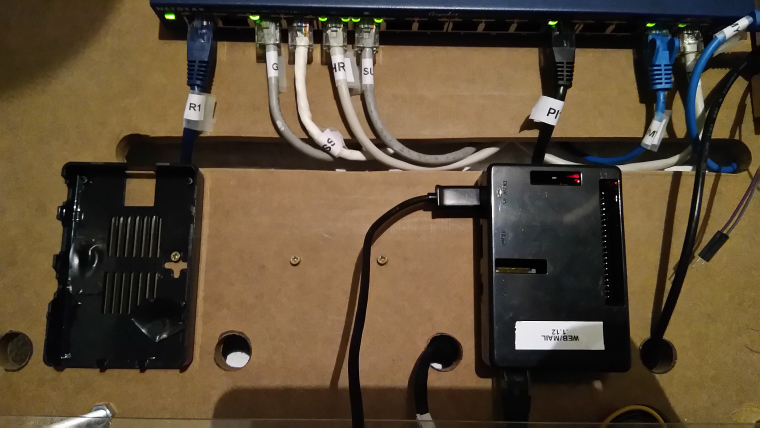
    @sundberg84 Sorry for the stupid question, but what holds your WEB/MAIL black box in place?

    S Offline
    S Offline
    sundberg84
    Hardware Contributor
    wrote on last edited by sundberg84
    #390

    @neverdie said in What did you build today (Pictures) ?:

    @sundberg84 Sorry for the stupid question, but what holds your WEB/MAIL black box in place?

    Screws.
    0_1518797972773_IMG_20180216_171855.jpg

    Controller: Proxmox VM - Home Assistant
    MySensors GW: Arduino Uno - W5100 Ethernet, Gw Shield Nrf24l01+ 2,4Ghz
    MySensors GW: Arduino Uno - Gw Shield RFM69, 433mhz
    RFLink GW - Arduino Mega + RFLink Shield, 433mhz

    1 Reply Last reply
    0
    • S sundberg84

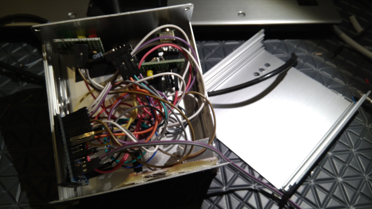
      0_1518791218187_15187911952321497205782.jpg

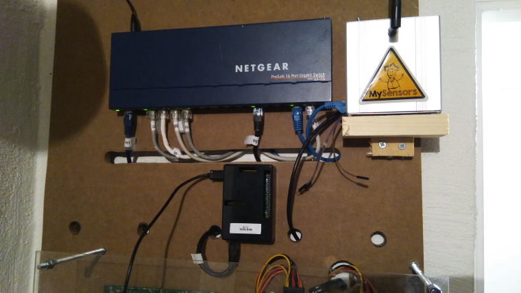
      Today some maintenance on my GW.

      Added a ground wire for debug and also corrected a buildmisstske and grounded the case.

      And relocated (let's hope for the best) it to my new HA DIY board...
      0_1518792236611_15187922282851484593467.jpg

      Y Offline
      Y Offline
      Yveaux
      Mod
      wrote on last edited by
      #391

      @sundberg84 +1 for the mySensors sticker!

      http://yveaux.blogspot.nl

      1 Reply Last reply
      2
      • P Offline
        P Offline
        petewill
        Admin
        wrote on last edited by
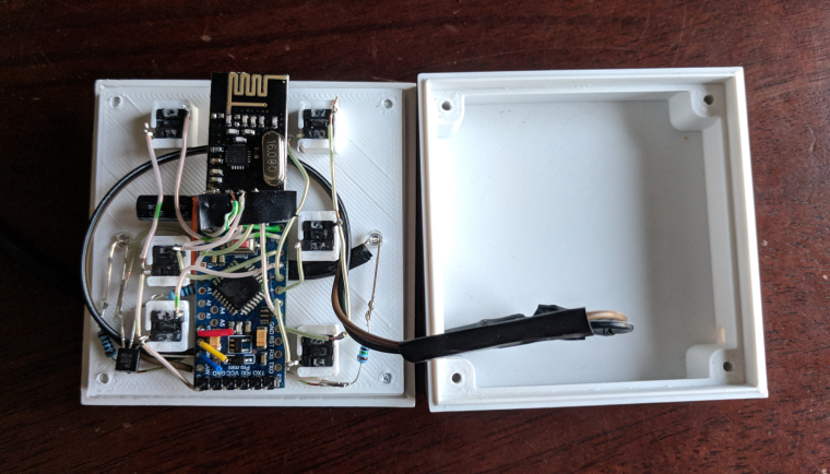
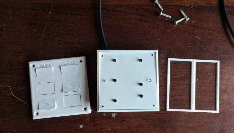
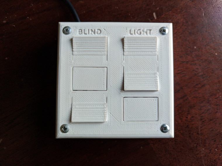
        #392

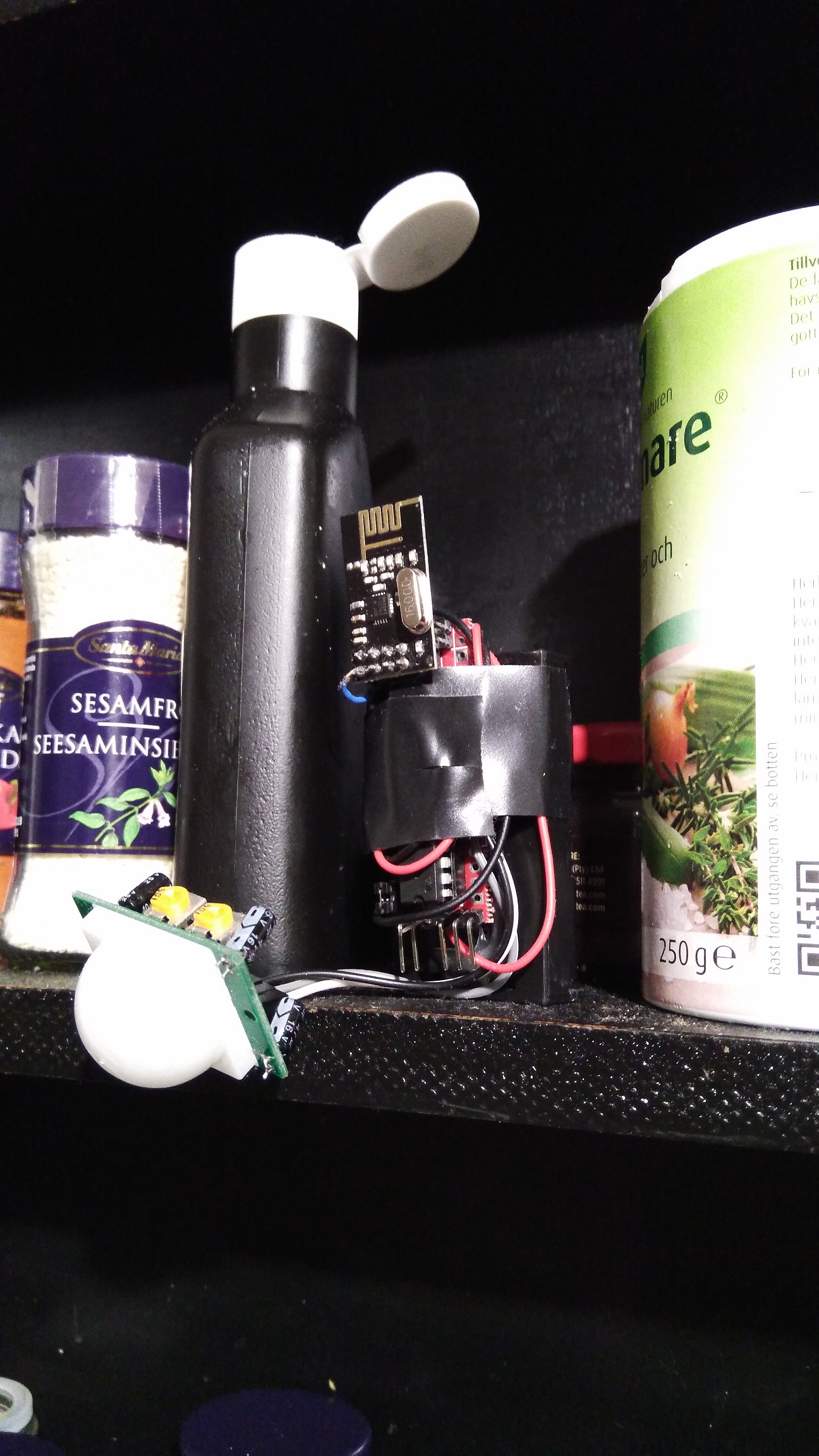
        My son and I finally finished his first MySensors project- a remote control for his room. He wasn't too interested but you have to start somewhere right...? :)
        Question for you all... what are you doing (if anything) to vent the fumes from soldering? I haven't really been worried about it in the past but it makes me nervous with my son doing it with me.
        Anyway, here are the pictures.
        0_1518837057065_IMG_20180216_171013.jpg
        0_1518837070467_IMG_20180216_171125.jpg
        0_1518837089935_IMG_20180216_171709.jpg

        My "How To" home automation video channel: https://www.youtube.com/channel/UCq_Evyh5PQALx4m4CQuxqkA

        N D mfalkviddM gohanG N 5 Replies Last reply
        5
        • P petewill

          My son and I finally finished his first MySensors project- a remote control for his room. He wasn't too interested but you have to start somewhere right...? :)
          Question for you all... what are you doing (if anything) to vent the fumes from soldering? I haven't really been worried about it in the past but it makes me nervous with my son doing it with me.
          Anyway, here are the pictures.
          0_1518837057065_IMG_20180216_171013.jpg
          0_1518837070467_IMG_20180216_171125.jpg
          0_1518837089935_IMG_20180216_171709.jpg

          N Offline
          N Offline
          NeverDie
          Hero Member
          wrote on last edited by NeverDie
          #393

          @petewill What up with the red, yellow, and blue wires on the pro mini?

          Also, did you print the case with a volcano?

          1 Reply Last reply
          0
          • P petewill

            My son and I finally finished his first MySensors project- a remote control for his room. He wasn't too interested but you have to start somewhere right...? :)
            Question for you all... what are you doing (if anything) to vent the fumes from soldering? I haven't really been worried about it in the past but it makes me nervous with my son doing it with me.
            Anyway, here are the pictures.

            0_1518837057065_IMG_20180216_171013.jpg
            0_1518837070467_IMG_20180216_171125.jpg
            0_1518837089935_IMG_20180216_171709.jpg

            D Offline
            D Offline
            dbemowsk
            wrote on last edited by
            #394

            @petewill That's awesome. Did you work with him too on the design of the box? Great job.

            Vera Plus running UI7 with MySensors, Sonoffs and 1-Wire devices
            Visit my website for more Bits, Bytes and Ramblings from me: http://dan.bemowski.info/

            1 Reply Last reply
            0
            • P petewill

              My son and I finally finished his first MySensors project- a remote control for his room. He wasn't too interested but you have to start somewhere right...? :)
              Question for you all... what are you doing (if anything) to vent the fumes from soldering? I haven't really been worried about it in the past but it makes me nervous with my son doing it with me.
              Anyway, here are the pictures.

              0_1518837057065_IMG_20180216_171013.jpg
              0_1518837070467_IMG_20180216_171125.jpg
              0_1518837089935_IMG_20180216_171709.jpg

              mfalkviddM Offline
              mfalkviddM Offline
              mfalkvidd
              Mod
              wrote on last edited by
              #395

              @petewill I put a regular 120mm pc fan to blow the fumes sideways. Not perfect, but I think it is good enough for the short time I spend soldering.

              1 Reply Last reply
              1
              • P petewill

                My son and I finally finished his first MySensors project- a remote control for his room. He wasn't too interested but you have to start somewhere right...? :)
                Question for you all... what are you doing (if anything) to vent the fumes from soldering? I haven't really been worried about it in the past but it makes me nervous with my son doing it with me.
                Anyway, here are the pictures.

                0_1518837057065_IMG_20180216_171013.jpg
                0_1518837070467_IMG_20180216_171125.jpg
                0_1518837089935_IMG_20180216_171709.jpg

                gohanG Offline
                gohanG Offline
                gohan
                Mod
                wrote on last edited by
                #396

                @petewill is it battery powered? Can you share the code?

                S 1 Reply Last reply
                0
                • gohanG gohan

                  @petewill is it battery powered? Can you share the code?

                  S Offline
                  S Offline
                  sundberg84
                  Hardware Contributor
                  wrote on last edited by sundberg84
                  #397

                  @petewill , @gohan I use the same as @mfalkvidd and its pretty much a PC fan with the wires to a 9v battery.... been thinking for a long time to make a more permanent sollution with a tubes from outside....

                  Controller: Proxmox VM - Home Assistant
                  MySensors GW: Arduino Uno - W5100 Ethernet, Gw Shield Nrf24l01+ 2,4Ghz
                  MySensors GW: Arduino Uno - Gw Shield RFM69, 433mhz
                  RFLink GW - Arduino Mega + RFLink Shield, 433mhz

                  1 Reply Last reply
                  1
                  • mfalkviddM Offline
                    mfalkviddM Offline
                    mfalkvidd
                    Mod
                    wrote on last edited by mfalkvidd
                    #398

                    0_1518863873465_File-2018-02-17,-11-32-40.jpg
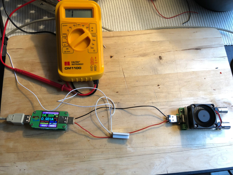
                    Today's test was to see if the regular reed switches can be closed by the magnetic field created by a 1A current.

                    I got an opportunity to try out my recently USB power meter and adjustable load.

                    Since I am not sure how the reed switch is mounted inside the sensor, I tried different orientations but nothing triggered the sensor. I also tried 2A but that wasn't enough either.

                    I need a non-invasive way to know if (how much) current is flowing in a DC cable. I was hoping the reed switch would be an easy way. My next hope is something like a SCT-013, unless someone has suggestions for other sensors. Requirements: 6-48V DC. 0.5-10A. I only need to know if the circuit is consuming >0.5A, no need for an exact measurement.

                    gohanG N 2 Replies Last reply
                    0
                    • mfalkviddM mfalkvidd

                      0_1518863873465_File-2018-02-17,-11-32-40.jpg
                      Today's test was to see if the regular reed switches can be closed by the magnetic field created by a 1A current.

                      I got an opportunity to try out my recently USB power meter and adjustable load.

                      Since I am not sure how the reed switch is mounted inside the sensor, I tried different orientations but nothing triggered the sensor. I also tried 2A but that wasn't enough either.

                      I need a non-invasive way to know if (how much) current is flowing in a DC cable. I was hoping the reed switch would be an easy way. My next hope is something like a SCT-013, unless someone has suggestions for other sensors. Requirements: 6-48V DC. 0.5-10A. I only need to know if the circuit is consuming >0.5A, no need for an exact measurement.

                      gohanG Offline
                      gohanG Offline
                      gohan
                      Mod
                      wrote on last edited by
                      #399

                      @mfalkvidd Hall sensor?

                      mfalkviddM 1 Reply Last reply
                      0
                      • gohanG gohan

                        @mfalkvidd Hall sensor?

                        mfalkviddM Offline
                        mfalkviddM Offline
                        mfalkvidd
                        Mod
                        wrote on last edited by mfalkvidd
                        #400

                        @gohan SCT-013 is a hall-based sensor I think. I was looking for more specific that just the type of sensor.

                        Y 1 Reply Last reply
                        0
                        • mfalkviddM mfalkvidd

                          @gohan SCT-013 is a hall-based sensor I think. I was looking for more specific that just the type of sensor.

                          Y Offline
                          Y Offline
                          Yveaux
                          Mod
                          wrote on last edited by
                          #401

                          @mfalkvidd said in What did you build today (Pictures) ?:

                          SCT-013 is a hall-based sensor I think.

                          No, it's only a current transformer, and you possibly need (at least) a burden resistor to measure the current. Ofcourse we already have a thread on it ;-)

                          http://yveaux.blogspot.nl

                          mfalkviddM 1 Reply Last reply
                          0
                          • Y Yveaux

                            @mfalkvidd said in What did you build today (Pictures) ?:

                            SCT-013 is a hall-based sensor I think.

                            No, it's only a current transformer, and you possibly need (at least) a burden resistor to measure the current. Ofcourse we already have a thread on it ;-)

                            mfalkviddM Offline
                            mfalkviddM Offline
                            mfalkvidd
                            Mod
                            wrote on last edited by
                            #402

                            @yveaux yes I've read that thread and I would choose one of the sct-013 variants that already contains a burden resistor.

                            1 Reply Last reply
                            0
                            • mfalkviddM mfalkvidd

                              0_1518863873465_File-2018-02-17,-11-32-40.jpg
                              Today's test was to see if the regular reed switches can be closed by the magnetic field created by a 1A current.

                              I got an opportunity to try out my recently USB power meter and adjustable load.

                              Since I am not sure how the reed switch is mounted inside the sensor, I tried different orientations but nothing triggered the sensor. I also tried 2A but that wasn't enough either.

                              I need a non-invasive way to know if (how much) current is flowing in a DC cable. I was hoping the reed switch would be an easy way. My next hope is something like a SCT-013, unless someone has suggestions for other sensors. Requirements: 6-48V DC. 0.5-10A. I only need to know if the circuit is consuming >0.5A, no need for an exact measurement.

                              N Offline
                              N Offline
                              NeverDie
                              Hero Member
                              wrote on last edited by NeverDie
                              #403

                              @mfalkvidd Didn't you play with electromagnets when you were a kid? At least try coiling the wire and maybe putting a metal core inside it. Use a lot of coils. The more the better. Then maybe your reed-type switch would have a chance of seeing enough magnetism to trigger it.

                              gohanG mfalkviddM 2 Replies Last reply
                              0
                              • N NeverDie

                                @mfalkvidd Didn't you play with electromagnets when you were a kid? At least try coiling the wire and maybe putting a metal core inside it. Use a lot of coils. The more the better. Then maybe your reed-type switch would have a chance of seeing enough magnetism to trigger it.

                                gohanG Offline
                                gohanG Offline
                                gohan
                                Mod
                                wrote on last edited by
                                #404

                                @neverdie wouldn't that choke the current passing through the coil? He said he needs 6-48V DC. 0.5-10A

                                1 Reply Last reply
                                0
                                • P Offline
                                  P Offline
                                  petewill
                                  Admin
                                  wrote on last edited by petewill
                                  #405

                                  @NeverDie The wires are there in case I need to upload a new bootloader. This sensor one of the first ones I have done where the Arduino isn't easily removable and I wanted to try to make it a little easier in case I had to change it.
                                  I used an original Prusa I3 MK2 to do the printing. This is in ABS (because I didn't have any white PLA) so the print is a little rougher than if it was done with PLA.

                                  @dbemowsk Thanks! No, my son didn't help with the case design (yet). It was from a previous project that I slightly modified. My son is 6 so he doesn't really have the attention span to do too much yet. I'm hoping that doing little parts of a project will be fun for him and eventually turn into full projects. :)

                                  @mfalkvidd & @sundberg84 Thanks. I guess I need to rig something up if he is going to be helping me more often...

                                  @gohan No, it's not battery powered. I didn't want to have to deal with changing batteries and there is a power outlet right near the location he wanted it. Here is the code:

                                  /**
                                    The MySensors Arduino library handles the wireless radio link and protocol
                                    between your home built sensors/actuators and HA controller of choice.
                                    The sensors forms a self healing radio network with optional repeaters. Each
                                    repeater and gateway builds a routing tables in EEPROM which keeps track of the
                                    network topology allowing messages to be routed to nodes.
                                  
                                    Created by Henrik Ekblad <henrik.ekblad@mysensors.org>
                                    Copyright (C) 2013-2015 Sensnology AB
                                    Full contributor list: https://github.com/mysensors/Arduino/graphs/contributors
                                  
                                    Documentation: http://www.mysensors.org
                                    Support Forum: http://forum.mysensors.org
                                  
                                    This program is free software; you can redistribute it and/or
                                    modify it under the terms of the GNU General Public License
                                    version 2 as published by the Free Software Foundation.
                                  
                                  *******************************
                                  
                                    REVISION HISTORY
                                    Version 1.0 - PeteWill
                                  
                                   
                                  */
                                  
                                  #define SKETCH_NAME "Controller"
                                  #define SKETCH_VERSION "1.0"
                                  
                                  //Child (sensor) name that will be sent to gateway
                                  #define CONTROLLER_CHILD_NAME "Room Control"
                                  
                                  // Enable debug prints to serial monitor
                                  #define MY_DEBUG //MySensors debug messages
                                  #define LOCAL_DEBUG //Code specific debug messages
                                  
                                  // Enable and select radio type attached
                                  #define MY_RADIO_NRF24
                                  //#define MY_RADIO_RFM69
                                  
                                  #define MY_RF24_PA_LEVEL RF24_PA_HIGH //Options: RF24_PA_MIN, RF24_PA_LOW, RF24_PA_HIGH, RF24_PA_MAX
                                  #define MY_RF24_CHANNEL  76
                                  #define MY_NODE_ID 1  //Manually set the node ID here. Comment out to auto assign
                                  
                                  #include <MySensors.h>
                                  #include <Bounce2.h>
                                  
                                  #define SCENE_CHILD_ID 0
                                  
                                  #define BAUD_RATE 57600
                                  
                                  #ifdef LOCAL_DEBUG
                                  #define dbg(...)   Serial.print(__VA_ARGS__)
                                  #define dbgln(...) Serial.println(__VA_ARGS__)
                                  #else
                                  #define dbg(x)
                                  #define dbgln(x)
                                  #endif
                                  
                                  //Button Pins -- Arduino Digital I/O pin button is connected to
                                  #define BLIND_UP_PIN 5
                                  #define BLIND_STOP_PIN 4
                                  #define BLIND_DOWN_PIN 3
                                  #define LIGHT_ON_PIN 8
                                  #define LIGHT_OFF_PIN 7
                                  #define EXTRA_BUTTON_PIN 6
                                  #define LED_PIN A0 //Pin for the LED transistor
                                  
                                  #define FLASH_TIME 300 //Amount of time to flash the LED (in milliseconds)
                                  
                                  #define ARRAY_SIZE(x) (sizeof(x)/sizeof(x[0]))
                                  
                                  uint8_t ledOn = 0;
                                  uint32_t ledMillis; //Used for tracking the LED flash time
                                  
                                  
                                  //The sceneNum array corresponds with the buttonPins array so if a button pin is read, it will send the scene number to the gateway
                                  int sceneNum[] = {0, 1, 2, 3, 4, 5};
                                  
                                  uint8_t buttonPins[] = {
                                    BLIND_UP_PIN,
                                    BLIND_STOP_PIN,
                                    BLIND_DOWN_PIN,
                                    LIGHT_ON_PIN,
                                    LIGHT_OFF_PIN,
                                    EXTRA_BUTTON_PIN
                                  };
                                  
                                  //Debouncer is used for the buttons.  Need to have the same number as the total buttons.
                                  Bounce debouncer[] = {
                                    Bounce(),
                                    Bounce(),
                                    Bounce(),
                                    Bounce(),
                                    Bounce(),
                                    Bounce()
                                  };
                                  
                                  //used to keep track of previous values contact sensor values
                                  uint8_t buttonPrev[] = {1, 1, 1, 1, 1, 1};
                                  
                                  MyMessage scene(SCENE_CHILD_ID, V_SCENE_ON);
                                  
                                  void before()
                                  {
                                  #ifdef LOCAL_DEBUG
                                    Serial.begin(BAUD_RATE);
                                  #endif
                                  }
                                  
                                  void presentation()
                                  {
                                    // Send the sketch version information to the gateway
                                    sendSketchInfo(SKETCH_NAME, SKETCH_VERSION);
                                  
                                    // Register all sensors to gw (they will be created as child devices)
                                    present(SCENE_CHILD_ID, S_SCENE_CONTROLLER, CONTROLLER_CHILD_NAME);
                                  }
                                  
                                  void setup() {
                                    //Set up Pins
                                    for (int i = 0; i < ARRAY_SIZE(buttonPins); i++) {
                                  
                                      // Setup the pins
                                      pinMode(buttonPins[i], INPUT_PULLUP);
                                  
                                      // After setting up the button, setup debouncer
                                      debouncer[i].attach(buttonPins[i]);
                                      debouncer[i].interval(100);
                                      dbg(F("Set up contact Pin: "));
                                      dbgln(buttonPins[i]);
                                    }
                                  
                                    pinMode(LED_PIN, OUTPUT);
                                  }
                                  
                                  void loop() {
                                    uint32_t currentMillis = millis();
                                    for (int i = 0; i < ARRAY_SIZE(buttonPins); i++) {
                                      debouncer[i].update();
                                      // Get the update value
                                      uint8_t value = debouncer[i].read();
                                      if (value != buttonPrev[i]) {
                                        dbg(F("Value is for sensor #"));
                                        dbg(buttonPins[i]);
                                        dbg(F(" is "));
                                        dbgln(value);
                                  
                                        if (value == 0)
                                        {
                                          //Button is pressed send scene value
                                          send(scene.set(sceneNum[i]));
                                  
                                          ledOn = 1;
                                          ledMillis = currentMillis;
                                        }
                                        buttonPrev[i] = value;
                                      }
                                    }
                                    if (ledOn)
                                    {
                                      digitalWrite(LED_PIN, HIGH);
                                  
                                      if (currentMillis - ledMillis > FLASH_TIME)
                                      {
                                        ledOn = 0;
                                        digitalWrite(LED_PIN, LOW);
                                      }
                                    }
                                  }


                                  My "How To" home automation video channel: https://www.youtube.com/channel/UCq_Evyh5PQALx4m4CQuxqkA

                                  1 Reply Last reply
                                  0
                                  • N NeverDie

                                    @mfalkvidd Didn't you play with electromagnets when you were a kid? At least try coiling the wire and maybe putting a metal core inside it. Use a lot of coils. The more the better. Then maybe your reed-type switch would have a chance of seeing enough magnetism to trigger it.

                                    mfalkviddM Offline
                                    mfalkviddM Offline
                                    mfalkvidd
                                    Mod
                                    wrote on last edited by
                                    #406

                                    @neverdie said in What did you build today (Pictures) ?:

                                    @mfalkvidd Didn't you play with electromagnets when you were a kid? At least try coiling the wire and maybe putting a metal core inside it. Use a lot of coils. The more the better. Then maybe your reed-type switch would have a chance of seeing enough magnetism to trigger it.

                                    Yes, but that would unfortunately completely defeat my purpose. The device should be easy to install (I can't expect the end-user to coil their cable) and work with cables that are designed for >10A which means they will be too thick to coil. I understand that I did not mention all aspects of the use case in my post though so thanks anyway.

                                    N 1 Reply Last reply
                                    0
                                    • P petewill

                                      My son and I finally finished his first MySensors project- a remote control for his room. He wasn't too interested but you have to start somewhere right...? :)
                                      Question for you all... what are you doing (if anything) to vent the fumes from soldering? I haven't really been worried about it in the past but it makes me nervous with my son doing it with me.
                                      Anyway, here are the pictures.

                                      0_1518837057065_IMG_20180216_171013.jpg
                                      0_1518837070467_IMG_20180216_171125.jpg
                                      0_1518837089935_IMG_20180216_171709.jpg

                                      N Offline
                                      N Offline
                                      Nca78
                                      Hardware Contributor
                                      wrote on last edited by
                                      #407

                                      @petewill said in What did you build today (Pictures) ?:

                                      Question for you all... what are you doing (if anything) to vent the fumes from soldering? I haven't really been worried about it in the past but it makes me nervous with my son doing it with me.

                                      I have a Hakko 493 clone, it has a carbon filter to absorb the smoke (or most of it) so it doesn't smell too much in the room when I need to solder for a long time and I can't open the windows. I don't have a link because I bought it in my local shop (it was cheaper than AliExpress + shipping), but you can easily find similar models or clones of the FA400 by searching "smoke absorber" on AliExpress.

                                      alt text

                                      P 1 Reply Last reply
                                      2
                                      • mfalkviddM mfalkvidd

                                        @neverdie said in What did you build today (Pictures) ?:

                                        @mfalkvidd Didn't you play with electromagnets when you were a kid? At least try coiling the wire and maybe putting a metal core inside it. Use a lot of coils. The more the better. Then maybe your reed-type switch would have a chance of seeing enough magnetism to trigger it.

                                        Yes, but that would unfortunately completely defeat my purpose. The device should be easy to install (I can't expect the end-user to coil their cable) and work with cables that are designed for >10A which means they will be too thick to coil. I understand that I did not mention all aspects of the use case in my post though so thanks anyway.

                                        N Offline
                                        N Offline
                                        NeverDie
                                        Hero Member
                                        wrote on last edited by NeverDie
                                        #408

                                        @mfalkvidd
                                        I had a similar requirement recently, which was determining when my CNC was finished. I decided to measure the current to decide that. It's 24VDC and might have a current as high as 6amp in a theoretical worst case, but as little as 0.5a when moving just one of the stepper motors. So, what I came up with was this, which I've tested and it works:
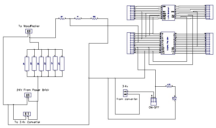
                                        0_1518882212781_cnc_current.jpg
                                        Basically, it uses six 5-watt 3 ohm resistors in parallel to create a 1/2-ohm sense resistor, which an arduino then measures the voltage drop across by just doing an analog read from an analog GPIO pin across a voltage divider. I don't really know your use-case, but maybe you could adapt it for your application? You can ignore the LoRa module, which in my case I use to send out a signal to a remote receiver inside my house that the CNC print job (in the garage) is done.

                                        1 Reply Last reply
                                        0
                                        • S Offline
                                          S Offline
                                          sundberg84
                                          Hardware Contributor
                                          wrote on last edited by sundberg84
                                          #409

                                          I made a MysX template for anyone who wants to create a MysX board to any EasyPCB in KiCadd.
                                          Found here: https://github.com/sundberg84/HomeAutomation/tree/master/MysX template EasyPCB
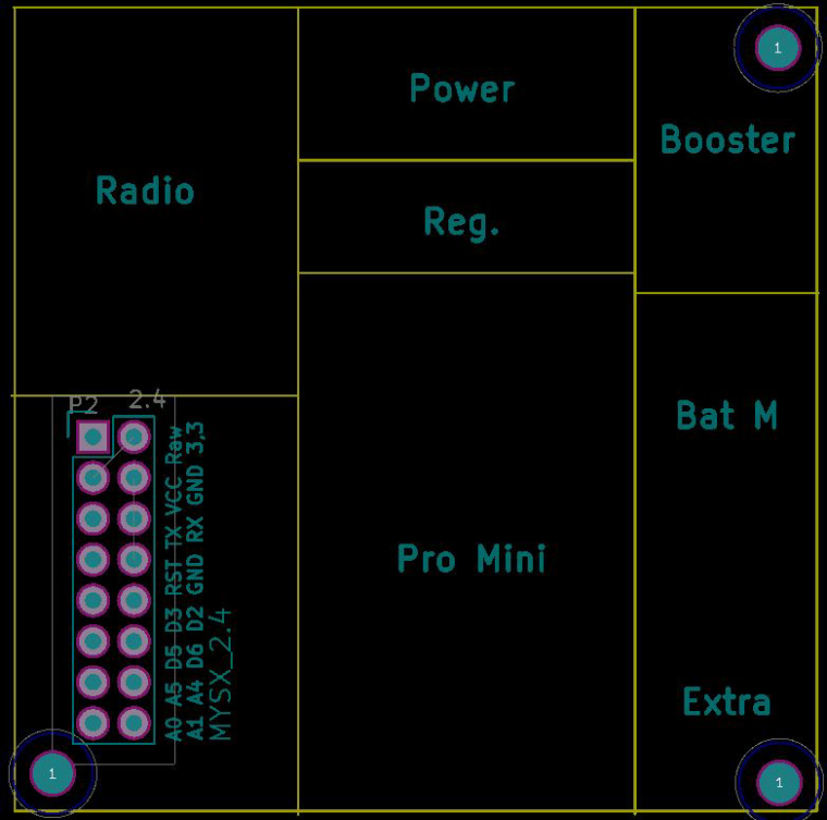
                                          0_1518893898944_pcb.JPG

                                          Controller: Proxmox VM - Home Assistant
                                          MySensors GW: Arduino Uno - W5100 Ethernet, Gw Shield Nrf24l01+ 2,4Ghz
                                          MySensors GW: Arduino Uno - Gw Shield RFM69, 433mhz
                                          RFLink GW - Arduino Mega + RFLink Shield, 433mhz

                                          1 Reply Last reply
                                          3

                                          Hello! It looks like you're interested in this conversation, but you don't have an account yet.

                                          Getting fed up of having to scroll through the same posts each visit? When you register for an account, you'll always come back to exactly where you were before, and choose to be notified of new replies (either via email, or push notification). You'll also be able to save bookmarks and upvote posts to show your appreciation to other community members.

                                          With your input, this post could be even better 💗

                                          Register Login
                                          Reply
                                          • Reply as topic
                                          Log in to reply
                                          • Oldest to Newest
                                          • Newest to Oldest
                                          • Most Votes


                                          13

                                          Online

                                          12.0k

                                          Users

                                          11.2k

                                          Topics

                                          113.4k

                                          Posts


                                          Copyright 2025 TBD   |   Forum Guidelines   |   Privacy Policy   |   Terms of Service
                                          • Login

                                          • Don't have an account? Register

                                          • Login or register to search.
                                          • First post
                                            Last post
                                          0
                                          • MySensors
                                          • OpenHardware.io
                                          • Categories
                                          • Recent
                                          • Tags
                                          • Popular