SCT-013-030 to measure watt
-
Hi,
I would like to reach the watt usage. I would like to use SCT-013-030, but as it seems to have a 3.5" connector, how can I connect this to my arduino? I can only see project where one is using pulse power. But with this one I would not need to install a new energy meter where I would like to read the watt usage.
Any tips and ideas?
-
Hi Patrik,
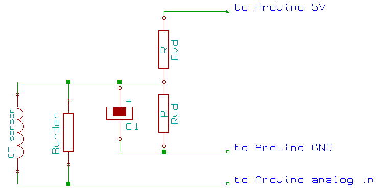
i use two of these to monitor my washer and dryer. Here is the schematic:
And the MS-Sketch:
/**
SCT_Dual_Sensor MySensors 2.0 EmonLib
 */

// Enable debug prints

//#define MY_DEBUG

// Set Static NodeID
#define MY_NODE_ID 5

// Enable and select radio type attached

#define MY_RADIO_RFM69
#define MY_RFM69_FREQUENCY RF69_868MHZ
#define MY_RFM69_NETWORKID 121
#define MY_RFM69_ENABLE_ENCRYPTION


// Enable repeater functionality for this node
#define MY_REPEATER_FEATURE


#include <SPI.h>
#include <MySensors.h>
#include <EmonLib.h>


#define ANALOG_INPUT_SENSOR1  1
#define ANALOG_INPUT_SENSOR2  2


#define CHILD_ID_PWR1 1              // Id of the sensor child
#define CHILD_ID_PWR2 2              // Id of the sensor child
#define CHILD_ID_RSSI 7              // Id for RSSI Value
//Init Emon
EnergyMonitor emon1;
EnergyMonitor emon2;


//Set Vars
unsigned long SLEEP_TIME = 60000 - 3735; // sleep for 60 seconds (-4 seconds to calculate values)
long wattsum1 = 0;
double kwh1 = 0;
double wh1= 0;
int minutes1 = 61;
long wattsum2 = 0;
double kwh2 = 0;
double wh2 = 0;
int minutes2 = 61;
//Int Messages
MyMessage wattMsg1(CHILD_ID_PWR1,V_WATT);
MyMessage kwhMsg1(CHILD_ID_PWR1,V_KWH);
MyMessage wattMsg2(CHILD_ID_PWR2,V_WATT);
MyMessage kwhMsg2(CHILD_ID_PWR2,V_KWH);
MyMessage rssiMsg(CHILD_ID_RSSI,V_TEXT);


void setup()
{
 emon1.current(ANALOG_INPUT_SENSOR1, 30);             // Current: input pin, calibration. stock = 30
 emon2.current(ANALOG_INPUT_SENSOR2, 30);             // Current: input pin, calibration. stock = 30
 double Irms1 = emon1.calcIrms(1480);  // initial boot to charge up capacitor (no reading is taken) - testing
 double Irms2 = emon2.calcIrms(1480);  // initial boot to charge up capacitor (no reading is taken) - testing
}

void presentation() {
  // Send the sketch version information to the gateway and Controller
  sendSketchInfo("Energy Meter Dual SCT013", "0.1");

  // Register this device as power sensor
  present(CHILD_ID_PWR1, S_POWER);
  present(CHILD_ID_PWR2, S_POWER);
  present(CHILD_ID_RSSI, S_INFO);
}

void loop()
{


  // power used each minute
  if (minutes1 < 60) {
    double Irms1 = emon1.calcIrms(1480);  // Calculate Irms only
    if (Irms1 < 0.3) Irms1 = 0;
    long watt1 = Irms1*230.0;  // default was 230 but our local voltage is about 240
    wattsum1 = wattsum1+watt1;
    minutes1++;
    send(wattMsg1.set(watt1));  // Send watt value to gw
    Serial.print(watt1);         // Apparent power
    Serial.print("W, I= ");
    Serial.print(Irms1);          // Irms

    int var1 = _radio.RSSI;
    send(rssiMsg.set(var1));  // Send RSSI value to gw
  }
  // end power used each minute
   if (minutes2 < 60) {
    double Irms2 = emon2.calcIrms(1480);  // Calculate Irms only
    if (Irms2 < 0.3) Irms2 = 0;
    long watt2 = Irms2*230.0;  // default was 230 but our local voltage is about 240
    wattsum2 = wattsum2+watt2;
    minutes2++;
    send(wattMsg2.set(watt2));  // Send watt value to gw

    Serial.print(watt2);         // Apparent power
    Serial.print("W, I= ");
    Serial.print(Irms2);          // Irms
  }
  // end power used each minute

  // hours KW reading
  if (minutes1 >= 60) {
    wh1 = wh1 + wattsum1/60;
    kwh1 = wh1/1000;
    send(kwhMsg1.set(kwh1, 4)); // Send kwh value to gw
    wattsum1 = 0;
    minutes1 = 0;
  // end of hourly KW reading

  }
    // hours KW reading
  if (minutes2 >= 60) {
    wh2 = wh2 + wattsum2/60;
    kwh2 = wh2/1000;
    send(kwhMsg2.set(kwh2, 4)); // Send kwh value to gw
    wattsum2 = 0;
    minutes2 = 0;
  // end of hourly KW reading

  }
//sleep until the next minute
sleep(SLEEP_TIME);
}
Also check this site : https://openenergymonitor.org/emon/buildingblocks/ct-sensors-interface
-
Hi Tmaster,
the SCT-013-030 have an build in burden, the SCT-013-000 dont have one. So you need to calculate the right burden and set the right calibration value (see https://openenergymonitor.org/emon/buildingblocks/how-to-build-an-arduino-energy-monitor-measuring-current-only)
-
So I have a question on this. I have a couple of the SCT-013-050 sensors, but plan on purchasing some of the SCT-013-000 sensors as I will need to read higher amperage from my incoming mains lines. The SCT-013-030 (and I think the SCT-013-050) contain the burden resistor. The open energy monitor project says to choose the burden resistor based on the voltage that you are running the arduino at (3.3 or 5 volts) . My question is the ones that have the burden resistor built in, what voltage is it designed to run at?
Vera Plus running UI7 with MySensors, Sonoffs and 1-Wire devices
Visit my website for more Bits, Bytes and Ramblings from me: http://dan.bemowski.info/ -
So I have a question on this. I have a couple of the SCT-013-050 sensors, but plan on purchasing some of the SCT-013-000 sensors as I will need to read higher amperage from my incoming mains lines. The SCT-013-030 (and I think the SCT-013-050) contain the burden resistor. The open energy monitor project says to choose the burden resistor based on the voltage that you are running the arduino at (3.3 or 5 volts) . My question is the ones that have the burden resistor built in, what voltage is it designed to run at?
@dbemowsk
Short answer: Built-in burden versions output 1V for rated current. Therefore 030 version has 1V for 30A, and 050 has 1V for 50A current. Either 3.3 or 5V supply, 1Vrms swing is almost in ADC range. So you can use 1V output types in any system. Just adjust the calibration constant in sketch.Long answer: SCT-013-000 version user-selected burden let you control voltage output, so you can have i.e. 2.5Vp-p output for a 5V system or 1.65Vp-p for a 3.3V system to fully utilize ADC range.
Let's assume you select a burden for 1Vrms (±1.707 Vp-p) @50A (R=~28,28ohm) which will be identical to a 050 model, however selecting a burden for 1.76 Vrms (±2,49Vp-p)@50A will have better resolution (mV per ADC step) in a 5V system.
Ideal value calculation is stated as: Burden Resistor (ohms) = (AREF * CT TURNS) / (2√2 * max primary current) So, ~68 ohm will use whole 0-5V range (±2,49Vp-p) OR ~47 ohm in 0-3.3V (±1,66Vp-p) range and will have best resolution.
-
@dbemowsk
Short answer: Built-in burden versions output 1V for rated current. Therefore 030 version has 1V for 30A, and 050 has 1V for 50A current. Either 3.3 or 5V supply, 1Vrms swing is almost in ADC range. So you can use 1V output types in any system. Just adjust the calibration constant in sketch.Long answer: SCT-013-000 version user-selected burden let you control voltage output, so you can have i.e. 2.5Vp-p output for a 5V system or 1.65Vp-p for a 3.3V system to fully utilize ADC range.
Let's assume you select a burden for 1Vrms (±1.707 Vp-p) @50A (R=~28,28ohm) which will be identical to a 050 model, however selecting a burden for 1.76 Vrms (±2,49Vp-p)@50A will have better resolution (mV per ADC step) in a 5V system.
Ideal value calculation is stated as: Burden Resistor (ohms) = (AREF * CT TURNS) / (2√2 * max primary current) So, ~68 ohm will use whole 0-5V range (±2,49Vp-p) OR ~47 ohm in 0-3.3V (±1,66Vp-p) range and will have best resolution.
@Talat-Keleş Thanks for the response. Now that I look at the case of the CT, I see that it says 1V. I am a bit stumpped on how to adjust the sketch to measure the 0.5v p-p rather than the 2.5v p-p that it uses in the sketch.
Also, I am a bit confused on the calibration value (111.1) in this line:
emon1.current(1, 111.1); // Current: input pin, calibration.My assumption would be that that is the actual incoming voltage for it to use in calculating the current. Is this correct? If this is the case, would it be possible to use a transformer say from an old wall wart that would take the line voltage and bring it down to say 6 - 12 volts and read that somehow on another analog pin to get a more exact value for the calibration?
Vera Plus running UI7 with MySensors, Sonoffs and 1-Wire devices
Visit my website for more Bits, Bytes and Ramblings from me: http://dan.bemowski.info/ -
@Talat-Keleş Thanks for the response. Now that I look at the case of the CT, I see that it says 1V. I am a bit stumpped on how to adjust the sketch to measure the 0.5v p-p rather than the 2.5v p-p that it uses in the sketch.
Also, I am a bit confused on the calibration value (111.1) in this line:
emon1.current(1, 111.1); // Current: input pin, calibration.My assumption would be that that is the actual incoming voltage for it to use in calculating the current. Is this correct? If this is the case, would it be possible to use a transformer say from an old wall wart that would take the line voltage and bring it down to say 6 - 12 volts and read that somehow on another analog pin to get a more exact value for the calibration?
@dbemowsk said:
Now that I look at the case of the CT, I see that it says 1V. I am a bit stumpped on how to adjust the sketch to measure the 0.5v p-p rather than the 2.5v p-p that it uses in the sketch.
Your CT gives 1V already, there is nothing to change in sketch. That output is physical voltage on Analog pin. Just need to adjust calibration value to read correct Amps as:
Also, I am a bit confused on the calibration value (111.1) in this line:
emon1.current(1, 111.1); // Current: input pin, calibration.Since you own 050
emon1.current(1, 50);as calibration constant. All above calculations and given calibration values on web for 000 model.
My assumption would be that that is the actual incoming voltage for it to use in calculating the current. Is this correct? If this is the case, would it be possible to use a transformer say from an old wall wart that would take the line voltage and bring it down to say 6 - 12 volts and read that somehow on another analog pin to get a more exact value for the calibration?
I didn't clearly understand what you want to achieve. For current calibration you don't need voltage values. If you take apart a wall-wart you can use that for calculating real power, power factor etc.
-
@dbemowsk said:
Now that I look at the case of the CT, I see that it says 1V. I am a bit stumpped on how to adjust the sketch to measure the 0.5v p-p rather than the 2.5v p-p that it uses in the sketch.
Your CT gives 1V already, there is nothing to change in sketch. That output is physical voltage on Analog pin. Just need to adjust calibration value to read correct Amps as:
Also, I am a bit confused on the calibration value (111.1) in this line:
emon1.current(1, 111.1); // Current: input pin, calibration.Since you own 050
emon1.current(1, 50);as calibration constant. All above calculations and given calibration values on web for 000 model.
My assumption would be that that is the actual incoming voltage for it to use in calculating the current. Is this correct? If this is the case, would it be possible to use a transformer say from an old wall wart that would take the line voltage and bring it down to say 6 - 12 volts and read that somehow on another analog pin to get a more exact value for the calibration?
I didn't clearly understand what you want to achieve. For current calibration you don't need voltage values. If you take apart a wall-wart you can use that for calculating real power, power factor etc.
@Talat Keleş said:
For current calibration you don't need voltage values.
That's where I was confused. I thought that was a voltage calibration value for calculating watts using the formula:
P(watts) = I(Current) X E(Voltage)What I was talking about was getting an accurate wattage measurement by more precisely calculating the voltage using the transformer method. Now that I look at the sketch closer, that would be more for this line of code:
Serial.print(Irms*230.0);Where you would use the transformer to more precisely calculate the voltage to use in the sketch. In the example sketch they use an estimated value of 230.0.
Vera Plus running UI7 with MySensors, Sonoffs and 1-Wire devices
Visit my website for more Bits, Bytes and Ramblings from me: http://dan.bemowski.info/ -
@Talat Keleş said:
For current calibration you don't need voltage values.
That's where I was confused. I thought that was a voltage calibration value for calculating watts using the formula:
P(watts) = I(Current) X E(Voltage)What I was talking about was getting an accurate wattage measurement by more precisely calculating the voltage using the transformer method. Now that I look at the sketch closer, that would be more for this line of code:
Serial.print(Irms*230.0);Where you would use the transformer to more precisely calculate the voltage to use in the sketch. In the example sketch they use an estimated value of 230.0.
@dbemowsk
For precise wattage measurement you need transformer as you think. Irms*230.0 is just a rough estimation. You can measure outlet voltage and use that value in sketch for better estimation.With transformer you use calcVI() instead of Irms*230. i.e below sketch, that measure both I and V, and calculate power (watt and VA, and other AC related stuff):
#include "EmonLib.h" // Include Emon Library EnergyMonitor emon1; // Create an instance void setup() { Serial.begin(9600); emon1.voltage(2, 234.26, 1.7); // Voltage: input pin, calibration, phase_shift emon1.current(1, 111.1); // Current: input pin, calibration. } void loop() { emon1.calcVI(20,2000); // Calculate all. No.of crossings, time-out emon1.serialprint(); // Print out all variables } -
@dbemowsk
For precise wattage measurement you need transformer as you think. Irms*230.0 is just a rough estimation. You can measure outlet voltage and use that value in sketch for better estimation.With transformer you use calcVI() instead of Irms*230. i.e below sketch, that measure both I and V, and calculate power (watt and VA, and other AC related stuff):
#include "EmonLib.h" // Include Emon Library EnergyMonitor emon1; // Create an instance void setup() { Serial.begin(9600); emon1.voltage(2, 234.26, 1.7); // Voltage: input pin, calibration, phase_shift emon1.current(1, 111.1); // Current: input pin, calibration. } void loop() { emon1.calcVI(20,2000); // Calculate all. No.of crossings, time-out emon1.serialprint(); // Print out all variables }@Talat-Keleş Perfect. Thanks for all your help.
Hello! It looks like you're interested in this conversation, but you don't have an account yet.
Getting fed up of having to scroll through the same posts each visit? When you register for an account, you'll always come back to exactly where you were before, and choose to be notified of new replies (either via email, or push notification). You'll also be able to save bookmarks and upvote posts to show your appreciation to other community members.
With your input, this post could be even better 💗
Register Login