What did you build today (Pictures) ?

-
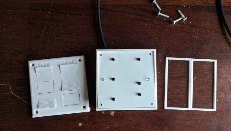
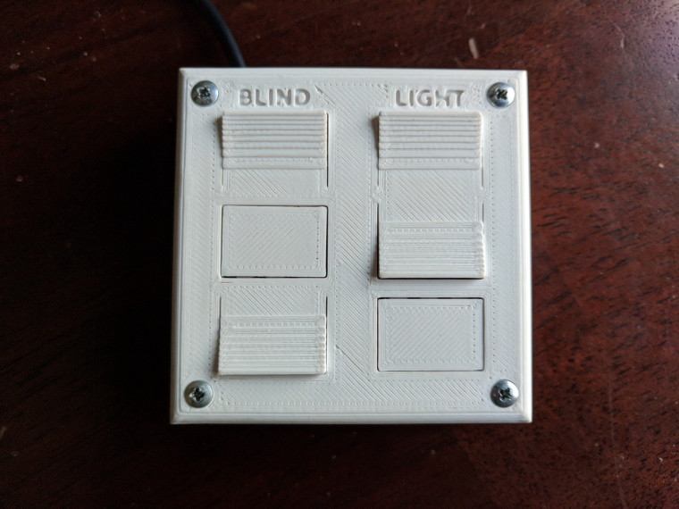
My son and I finally finished his first MySensors project- a remote control for his room. He wasn't too interested but you have to start somewhere right...? :)
Question for you all... what are you doing (if anything) to vent the fumes from soldering? I haven't really been worried about it in the past but it makes me nervous with my son doing it with me.
Anyway, here are the pictures.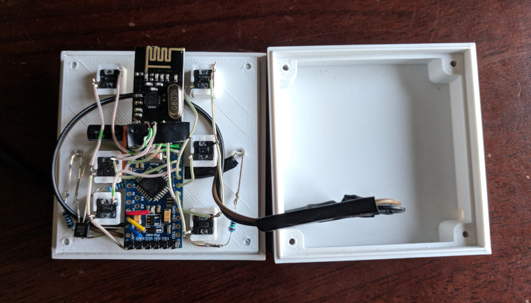
-
@petewill , @gohan I use the same as @mfalkvidd and its pretty much a PC fan with the wires to a 9v battery.... been thinking for a long time to make a more permanent sollution with a tubes from outside....
-
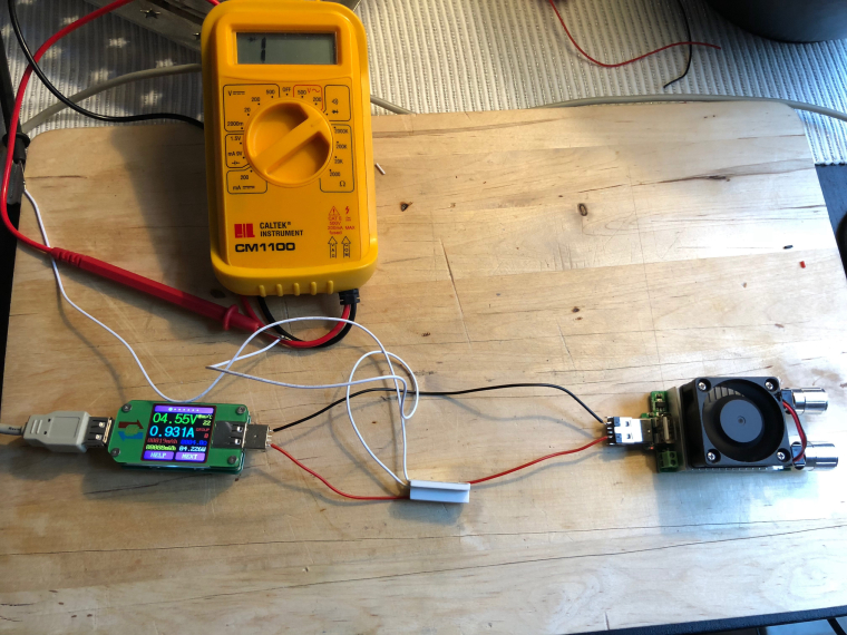
Today's test was to see if the regular reed switches can be closed by the magnetic field created by a 1A current.I got an opportunity to try out my recently USB power meter and adjustable load.
Since I am not sure how the reed switch is mounted inside the sensor, I tried different orientations but nothing triggered the sensor. I also tried 2A but that wasn't enough either.
I need a non-invasive way to know if (how much) current is flowing in a DC cable. I was hoping the reed switch would be an easy way. My next hope is something like a SCT-013, unless someone has suggestions for other sensors. Requirements: 6-48V DC. 0.5-10A. I only need to know if the circuit is consuming >0.5A, no need for an exact measurement.
-
@mfalkvidd Hall sensor?
-
@gohan SCT-013 is a hall-based sensor I think. I was looking for more specific that just the type of sensor.
@mfalkvidd said in What did you build today (Pictures) ?:
SCT-013 is a hall-based sensor I think.
No, it's only a current transformer, and you possibly need (at least) a burden resistor to measure the current. Ofcourse we already have a thread on it ;-)
http://yveaux.blogspot.nl
-
@mfalkvidd said in What did you build today (Pictures) ?:
SCT-013 is a hall-based sensor I think.
No, it's only a current transformer, and you possibly need (at least) a burden resistor to measure the current. Ofcourse we already have a thread on it ;-)
-
Today's test was to see if the regular reed switches can be closed by the magnetic field created by a 1A current.I got an opportunity to try out my recently USB power meter and adjustable load.
Since I am not sure how the reed switch is mounted inside the sensor, I tried different orientations but nothing triggered the sensor. I also tried 2A but that wasn't enough either.
I need a non-invasive way to know if (how much) current is flowing in a DC cable. I was hoping the reed switch would be an easy way. My next hope is something like a SCT-013, unless someone has suggestions for other sensors. Requirements: 6-48V DC. 0.5-10A. I only need to know if the circuit is consuming >0.5A, no need for an exact measurement.
@mfalkvidd Didn't you play with electromagnets when you were a kid? At least try coiling the wire and maybe putting a metal core inside it. Use a lot of coils. The more the better. Then maybe your reed-type switch would have a chance of seeing enough magnetism to trigger it.
-
@mfalkvidd Didn't you play with electromagnets when you were a kid? At least try coiling the wire and maybe putting a metal core inside it. Use a lot of coils. The more the better. Then maybe your reed-type switch would have a chance of seeing enough magnetism to trigger it.
-
@NeverDie The wires are there in case I need to upload a new bootloader. This sensor one of the first ones I have done where the Arduino isn't easily removable and I wanted to try to make it a little easier in case I had to change it.
I used an original Prusa I3 MK2 to do the printing. This is in ABS (because I didn't have any white PLA) so the print is a little rougher than if it was done with PLA.@dbemowsk Thanks! No, my son didn't help with the case design (yet). It was from a previous project that I slightly modified. My son is 6 so he doesn't really have the attention span to do too much yet. I'm hoping that doing little parts of a project will be fun for him and eventually turn into full projects. :)
@mfalkvidd & @sundberg84 Thanks. I guess I need to rig something up if he is going to be helping me more often...
@gohan No, it's not battery powered. I didn't want to have to deal with changing batteries and there is a power outlet right near the location he wanted it. Here is the code:
/** The MySensors Arduino library handles the wireless radio link and protocol between your home built sensors/actuators and HA controller of choice. The sensors forms a self healing radio network with optional repeaters. Each repeater and gateway builds a routing tables in EEPROM which keeps track of the network topology allowing messages to be routed to nodes. Created by Henrik Ekblad <henrik.ekblad@mysensors.org> Copyright (C) 2013-2015 Sensnology AB Full contributor list: https://github.com/mysensors/Arduino/graphs/contributors Documentation: http://www.mysensors.org Support Forum: http://forum.mysensors.org This program is free software; you can redistribute it and/or modify it under the terms of the GNU General Public License version 2 as published by the Free Software Foundation. ******************************* REVISION HISTORY Version 1.0 - PeteWill */ #define SKETCH_NAME "Controller" #define SKETCH_VERSION "1.0" //Child (sensor) name that will be sent to gateway #define CONTROLLER_CHILD_NAME "Room Control" // Enable debug prints to serial monitor #define MY_DEBUG //MySensors debug messages #define LOCAL_DEBUG //Code specific debug messages // Enable and select radio type attached #define MY_RADIO_NRF24 //#define MY_RADIO_RFM69 #define MY_RF24_PA_LEVEL RF24_PA_HIGH //Options: RF24_PA_MIN, RF24_PA_LOW, RF24_PA_HIGH, RF24_PA_MAX #define MY_RF24_CHANNEL 76 #define MY_NODE_ID 1 //Manually set the node ID here. Comment out to auto assign #include <MySensors.h> #include <Bounce2.h> #define SCENE_CHILD_ID 0 #define BAUD_RATE 57600 #ifdef LOCAL_DEBUG #define dbg(...) Serial.print(__VA_ARGS__) #define dbgln(...) Serial.println(__VA_ARGS__) #else #define dbg(x) #define dbgln(x) #endif //Button Pins -- Arduino Digital I/O pin button is connected to #define BLIND_UP_PIN 5 #define BLIND_STOP_PIN 4 #define BLIND_DOWN_PIN 3 #define LIGHT_ON_PIN 8 #define LIGHT_OFF_PIN 7 #define EXTRA_BUTTON_PIN 6 #define LED_PIN A0 //Pin for the LED transistor #define FLASH_TIME 300 //Amount of time to flash the LED (in milliseconds) #define ARRAY_SIZE(x) (sizeof(x)/sizeof(x[0])) uint8_t ledOn = 0; uint32_t ledMillis; //Used for tracking the LED flash time //The sceneNum array corresponds with the buttonPins array so if a button pin is read, it will send the scene number to the gateway int sceneNum[] = {0, 1, 2, 3, 4, 5}; uint8_t buttonPins[] = { BLIND_UP_PIN, BLIND_STOP_PIN, BLIND_DOWN_PIN, LIGHT_ON_PIN, LIGHT_OFF_PIN, EXTRA_BUTTON_PIN }; //Debouncer is used for the buttons. Need to have the same number as the total buttons. Bounce debouncer[] = { Bounce(), Bounce(), Bounce(), Bounce(), Bounce(), Bounce() }; //used to keep track of previous values contact sensor values uint8_t buttonPrev[] = {1, 1, 1, 1, 1, 1}; MyMessage scene(SCENE_CHILD_ID, V_SCENE_ON); void before() { #ifdef LOCAL_DEBUG Serial.begin(BAUD_RATE); #endif } void presentation() { // Send the sketch version information to the gateway sendSketchInfo(SKETCH_NAME, SKETCH_VERSION); // Register all sensors to gw (they will be created as child devices) present(SCENE_CHILD_ID, S_SCENE_CONTROLLER, CONTROLLER_CHILD_NAME); } void setup() { //Set up Pins for (int i = 0; i < ARRAY_SIZE(buttonPins); i++) { // Setup the pins pinMode(buttonPins[i], INPUT_PULLUP); // After setting up the button, setup debouncer debouncer[i].attach(buttonPins[i]); debouncer[i].interval(100); dbg(F("Set up contact Pin: ")); dbgln(buttonPins[i]); } pinMode(LED_PIN, OUTPUT); } void loop() { uint32_t currentMillis = millis(); for (int i = 0; i < ARRAY_SIZE(buttonPins); i++) { debouncer[i].update(); // Get the update value uint8_t value = debouncer[i].read(); if (value != buttonPrev[i]) { dbg(F("Value is for sensor #")); dbg(buttonPins[i]); dbg(F(" is ")); dbgln(value); if (value == 0) { //Button is pressed send scene value send(scene.set(sceneNum[i])); ledOn = 1; ledMillis = currentMillis; } buttonPrev[i] = value; } } if (ledOn) { digitalWrite(LED_PIN, HIGH); if (currentMillis - ledMillis > FLASH_TIME) { ledOn = 0; digitalWrite(LED_PIN, LOW); } } } -
@mfalkvidd Didn't you play with electromagnets when you were a kid? At least try coiling the wire and maybe putting a metal core inside it. Use a lot of coils. The more the better. Then maybe your reed-type switch would have a chance of seeing enough magnetism to trigger it.
@neverdie said in What did you build today (Pictures) ?:
@mfalkvidd Didn't you play with electromagnets when you were a kid? At least try coiling the wire and maybe putting a metal core inside it. Use a lot of coils. The more the better. Then maybe your reed-type switch would have a chance of seeing enough magnetism to trigger it.
Yes, but that would unfortunately completely defeat my purpose. The device should be easy to install (I can't expect the end-user to coil their cable) and work with cables that are designed for >10A which means they will be too thick to coil. I understand that I did not mention all aspects of the use case in my post though so thanks anyway.
-
My son and I finally finished his first MySensors project- a remote control for his room. He wasn't too interested but you have to start somewhere right...? :)
Question for you all... what are you doing (if anything) to vent the fumes from soldering? I haven't really been worried about it in the past but it makes me nervous with my son doing it with me.
Anyway, here are the pictures.
@petewill said in What did you build today (Pictures) ?:
Question for you all... what are you doing (if anything) to vent the fumes from soldering? I haven't really been worried about it in the past but it makes me nervous with my son doing it with me.
I have a Hakko 493 clone, it has a carbon filter to absorb the smoke (or most of it) so it doesn't smell too much in the room when I need to solder for a long time and I can't open the windows. I don't have a link because I bought it in my local shop (it was cheaper than AliExpress + shipping), but you can easily find similar models or clones of the FA400 by searching "smoke absorber" on AliExpress.

-
@neverdie said in What did you build today (Pictures) ?:
@mfalkvidd Didn't you play with electromagnets when you were a kid? At least try coiling the wire and maybe putting a metal core inside it. Use a lot of coils. The more the better. Then maybe your reed-type switch would have a chance of seeing enough magnetism to trigger it.
Yes, but that would unfortunately completely defeat my purpose. The device should be easy to install (I can't expect the end-user to coil their cable) and work with cables that are designed for >10A which means they will be too thick to coil. I understand that I did not mention all aspects of the use case in my post though so thanks anyway.
@mfalkvidd
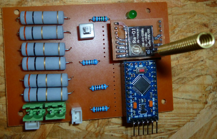
I had a similar requirement recently, which was determining when my CNC was finished. I decided to measure the current to decide that. It's 24VDC and might have a current as high as 6amp in a theoretical worst case, but as little as 0.5a when moving just one of the stepper motors. So, what I came up with was this, which I've tested and it works:
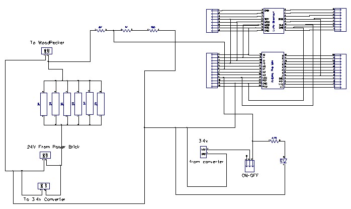
Basically, it uses six 5-watt 3 ohm resistors in parallel to create a 1/2-ohm sense resistor, which an arduino then measures the voltage drop across by just doing an analog read from an analog GPIO pin across a voltage divider. I don't really know your use-case, but maybe you could adapt it for your application? You can ignore the LoRa module, which in my case I use to send out a signal to a remote receiver inside my house that the CNC print job (in the garage) is done. -
I made a MysX template for anyone who wants to create a MysX board to any EasyPCB in KiCadd.
Found here: https://github.com/sundberg84/HomeAutomation/tree/master/MysX template EasyPCB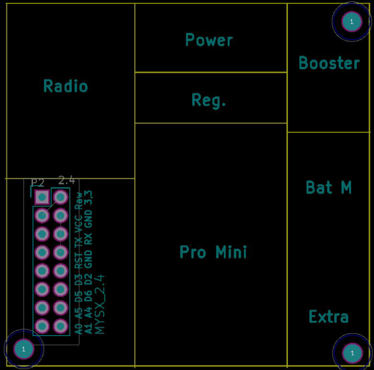
-
@petewill said in What did you build today (Pictures) ?:
Question for you all... what are you doing (if anything) to vent the fumes from soldering? I haven't really been worried about it in the past but it makes me nervous with my son doing it with me.
I have a Hakko 493 clone, it has a carbon filter to absorb the smoke (or most of it) so it doesn't smell too much in the room when I need to solder for a long time and I can't open the windows. I don't have a link because I bought it in my local shop (it was cheaper than AliExpress + shipping), but you can easily find similar models or clones of the FA400 by searching "smoke absorber" on AliExpress.
-
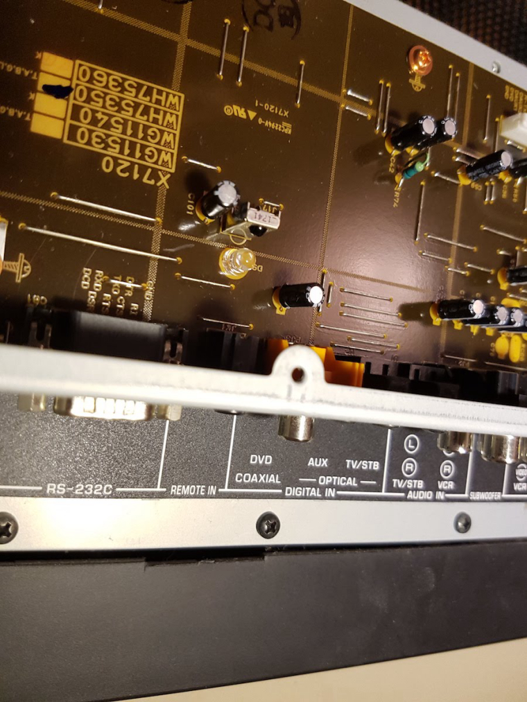
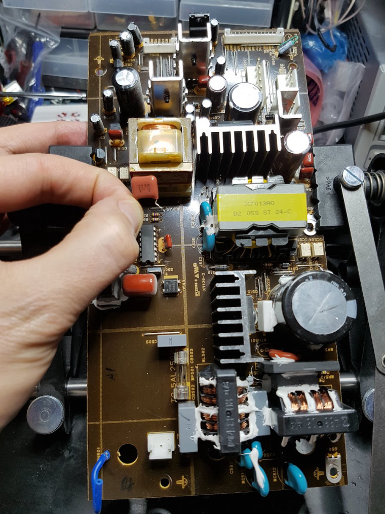
My old Yamaha YSP-1100 soundbar just decided to die.
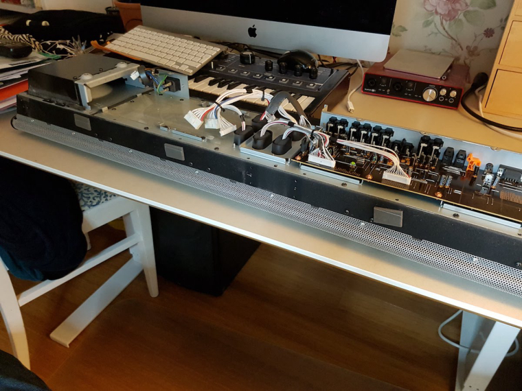
After some searching I found the problematic capacitor. A 22uF 600V had dropped to 6uF....
 !
!