Skip to content
  • MySensors
  • OpenHardware.io
  • Categories
  • Recent
  • Tags
  • Popular
Skins
  • Light
  • Brite
  • Cerulean
  • Cosmo
  • Flatly
  • Journal
  • Litera
  • Lumen
  • Lux
  • Materia
  • Minty
  • Morph
  • Pulse
  • Sandstone
  • Simplex
  • Sketchy
  • Spacelab
  • United
  • Yeti
  • Zephyr
  • Dark
  • Cyborg
  • Darkly
  • Quartz
  • Slate
  • Solar
  • Superhero
  • Vapor

  • Default (No Skin)
  • No Skin
Collapse
Brand Logo
A

ArduiSens

@ArduiSens
About
Posts
31
Topics
5
Shares
0
Groups
0
Followers
0
Following
0

Posts

Recent Best Controversial

  • eeBUS
    A ArduiSens

    Hello all,
    Is someone having experience with the (new) communication protocol used for energy devices like solar panel inverters, washing machines …? In Europe this protocol is trying to be the norm (many companies are supporting this protocol or are having the intention to do this). I read this protocol is available in the open domain.

    Links found:
    https://www.eebus.org/
    https://www.eebus.org/media-downloads/#_SPECIFICATIONS
    https://en.wikipedia.org/wiki/EEBUS
    https://www.youtube.com/watch?v=VV0igaf1rZs
    https://www.youtube.com/watch?v=GJXMs3wSpOg

    Dutch info: https://fwd.nl/smarthome/zo-werkt-eebus-de-taal-voor-slimme-energienetwerken/

    Are there ideas to write libraries, coding, hardware … to support this protocol with MySensors?

    General Discussion

  • 💬 Dual Channel 0-10V Dimmer
    A ArduiSens

    Hi Mardah, how this the progress on this project related to the software and testing?
    kind regards

    OpenHardware.io mysensors dimmer 0-10v

  • RS485, no communication
    A ArduiSens

    hello, maybe a hardware issue
    please check

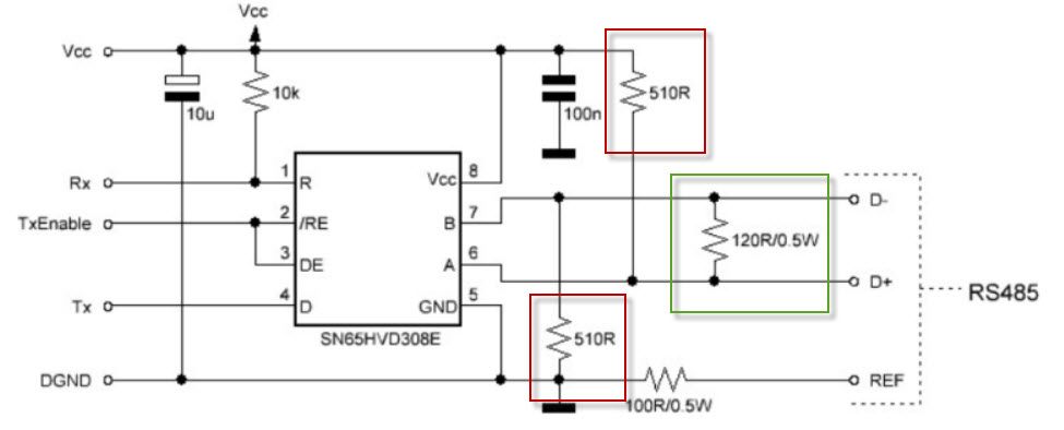
    Ref https://forum.mysensors.org/topic/4854/building-a-wired-rs485-sensor-network/99

    he 510 ohm pull up and pull down resistors are usually mounted on the master side. Theoretically it
    would be best to install it in the middle of your bus line. The 120 ohm termination resistor must always
    be used on distances greater than 1 meter and/or baud rates higher than 9600. It’s best to install it as a
    norm as noise and reflections will cause havoc on your communication once implemented in the field.
    The termination resistors should be mounted at both ends of the bus line. Please note that adding bias
    resistors will load the driver IC output. With the indicated values the max number of units on the bus
    line is limited to eight 12kΩ, sixteen 24kΩ, or thirty-two 48kΩ units.
    For further protection transient suppressors can be installed across the differential lines, from the Vcc to
    D+ and from GND to D-.!
    RS485.jpg

    Troubleshooting

  • 💬 Building a wired RS485 sensor network
    A ArduiSens

    I see there is a possibility the combine Ethernet with RS485.
    Maybe you can check the setup as they did here:

    https://www.openhardware.io/view/649/RS485-Ethernet-Gateway#tabs-comments

    https://github.com/feanor-anglin/GetWired-Project/blob/master/GetWired Ethernet Gateway/Gateway.ino

    Announcements

  • 💬 Building a wired RS485 sensor network
    A ArduiSens

    @Flyer said in 💬 Building a wired RS485 sensor network:

    ng to build

    Hi Flyer, As far as I know this is not possible.

    Announcements

  • Who has experience with (E34-DTU-2G4D20) Full Duplex RS232/RS485 to nRF24L01P ?
    A ArduiSens

    This can maybe a solution for having a bridge between RS485 and nRF24L01.

    Feature Requests

  • Who has experience with (E34-DTU-2G4D20) Full Duplex RS232/RS485 to nRF24L01P ?
    A ArduiSens

    Re: Bridge between RF24 and RS485
    https://www.aliexpress.com/item/4000512016252.html?spm=a2g0o.productlist.0.0.7879a483YoMye0&algo_pvid=fd05d00f-4103-4e95-a0c1-f8af3889cffa&algo_expid=fd05d00f-4103-4e95-a0c1-f8af3889cffa-10&btsid=0bb0623b16125608659071681e09c9&ws_ab_test=searchweb0_0,searchweb201602_,searchweb201603_
    thanks

    Feature Requests

  • sending two messages one after another
    A ArduiSens

    Hello all,
    is this solution added to the standard MySensor library?
    If so, in which version is it implemented?

    I want to be sure there are no missing messages when having a list of messages to be sent.

    many thanks in advance

    Development

  • Set output pin High before message initialising
    A ArduiSens

    @mfalkvidd
    OK, the before() works!

    0 MCO:BGN:INIT NODE,CP=RSNNA--,VER=2.1.1
    3 MCO:BGN:BFR
    running before() function
    2006 TSM:INIT
    2011 TSF:WUR:MS=0
    2012 TSM:INIT:TSP OK
    2014 TSM:INIT:STATID=25
    2016 TSF:SID:OK,ID=25
    2018 TSM:FPAR
    2036 TSF:MSG:SEND,25-25-255-255,s=255,c=3,t=7,pt=0,l=0,sg=0,ft=0,st=OK:
    2850 TSF:MSG:READ,0-0-25,s=255,c=3,t=8,pt=1,l=1,sg=0:0
    2855 TSF:MSG:FPAR OK,ID=0,D=1
    4043 TSM:FPAR:OK

    thanks for the cooperation mfalkvidd & rejoe2

    Feature Requests

  • Set output pin High before message initialising
    A ArduiSens

    hello rejoe2, you have to power the MAX chip before you come into the loop() because the first time you have to send the node configuration to the gw.
    Putting the

    pinMode(SENSOR_POWER_PIN, OUTPUT);
    digitalWrite(SENSOR_POWER_PIN, HIGH);

    code in the setup() is also too late.
    If the MAX isn't powered before, you get error messages because the node can't connect to the gw.

    btw the DE-PIN is not related to powering the transceiver --> right, it's a similar management, it was an example to find a solution

    Feature Requests

  • Set output pin High before message initialising
    A ArduiSens

    Is there a way to set an output pin high before sending the init message to the gateway?
    so before
    // Initialize messages
    MyMessage msgTemp(CHILD_ID_TEMP,V_TEMP);
    MyMessage sleepMsg(CHILD_ID_SLEEP, V_TEXT);

    I want to save energy (300µA) so I want to power the MAX485 only when sending messages.
    This is manageable in the sketch (set output pin high after returning from sleep mode, low before sleep) but at first start it isn't. I walked through the libraries but I didn't find the code where the DE pin is managed in order to send data to the MAX chip whch will send the data to the gateway. If I could find this I can make a similar set-up. Thanks in advance.

    Feature Requests

  • 💬 MySensors @Eindhoven Maker Fair 2017 2-3 September
    A ArduiSens

    Great job guys, I saw many interested people.
    The setup of the automated doll house was fascinating, also my son loved the sensor house (with the ghost)
    Only this, I saw myself in one of taken pictures but unfortunately without the MySensor t-shirt ;-(

    Announcements

  • NodeManager v1.6-dev: comments and issues
    A ArduiSens

    Hello,

    I see a problem when using setSleepSeconds / setPowerPins in combination with the serial RS485 option.

    void before() {
    // setup the serial port baud rate
    Serial.begin(MY_BAUD_RATE);
    nodeManager.setSleepSeconds(30);
    nodeManager.setPowerPins(11,12,1000);

    /*

    • Register below your sensors
      */
      nodeManager.registerSensor(SENSOR_DS18B20,3);

    gives a temperature value of 7368:
    0;255;3;0;9;TSF:MSG:READ,3-3-0,s=255,c=3,t=22,pt=5,l=4,sg=0:7368
    3;255;3;0;22;7368
    RECV S=3 I=255 C=3 T=22 P=


    void before() {
    // setup the serial port baud rate
    Serial.begin(MY_BAUD_RATE);
    nodeManager.setReportIntervalSeconds(50);

    /*

    • Register below your sensors
      */
      nodeManager.registerSensor(SENSOR_DS18B20,3);

    gives a correct value:
    0;255;3;0;9;TSF:MSG:READ,3-3-0,s=1,c=1,t=0,pt=7,l=5,sg=0:19.75
    3;1;1;0;0;19.75
    RECV S=3 I=1 C=1 T=0 P=

    NodeManager

  • NodeManager v1.6-dev: comments and issues
    A ArduiSens

    FYI
    I already had report this in "https://forum.mysensors.org/topic/6534/nodemanager/100", but in that case I was already using V1.6-dev version.

    *ArduiSens 4 days ago

    @user2684, why does NodeManager take so many sketch memory?
    e.g.
    (#define BATTERY_MANAGER 1; #define DEBUG 1; #define MODULE_DS18B20 1)
    sketch NodeManager RS485 config for DS18B20 --> 28730 bytes (93%) of program storage space. Maximum is 30720 bytes.

    own sketch for RS485 SR04T --> 17078 bytes (55%) of program storage space. Maximum is 30720 bytes.

    OK, DS18B20 and SR04T are not the same but DS18B20 is less complex, so 38% more memory is pretty much.*

    NodeManager

  • 💬 NodeManager
    A ArduiSens

    @Sergio, I know and it's OK. I'm just playing (trying to convert my RS485 projects).
    In the cases above I'm using Nano boards.

    OpenHardware.io contest2017 arduino newbie mysensors battery sensor

  • 💬 NodeManager
    A ArduiSens

    @user2684, why does NodeManager take so many sketch memory?
    e.g.
    (#define BATTERY_MANAGER 1; #define DEBUG 1; #define MODULE_DS18B20 1)
    sketch NodeManager RS485 config for DS18B20 --> 28730 bytes (93%) of program storage space. Maximum is 30720 bytes.

    own sketch for RS485 SR04T --> 17078 bytes (55%) of program storage space. Maximum is 30720 bytes.

    OK, DS18B20 and SR04T are not the same but DS18B20 is less complex, so 38% more memory is pretty much.
    Do I miss something?

    OpenHardware.io contest2017 arduino newbie mysensors battery sensor

  • 💬 NodeManager
    A ArduiSens

    @user2684, found the RS485 settings (thanks), but having problems with disabling the BATTERY_MANAGER option.
    We don't need this option in a RS485 serial wired network (or RS485 serial gateway).

    config.h:
    #define BATTERY_MANAGER 0

    gives following compiling errors:
    sketch\NodeManager.cpp: In member function 'void NodeManager::process(Request&)':
    NodeManager.cpp:3722: error: 'setBatteryReportSeconds' was not declared in this scope
    case 40: setBatteryReportSeconds(request.getValueInt()); break;
    NodeManager.cpp:3723: error: 'setBatteryReportHours' was not declared in this scope
    case 41: setBatteryReportHours(request.getValueInt()); break;
    NodeManager.cpp:3724: error: 'setBatteryReportDays' was not declared in this scope
    case 42: setBatteryReportDays(request.getValueInt()); break;

    exit status 1
    'setBatteryReportSeconds' was not declared in this scope

    OpenHardware.io contest2017 arduino newbie mysensors battery sensor

  • 💬 NodeManager
    A ArduiSens

    Hello, is there an option to use the (fantastic) Node Manager in a RS485 wired set-up?

    OpenHardware.io contest2017 arduino newbie mysensors battery sensor

  • 💬 Building a wired RS485 sensor network
    A ArduiSens

    Nofox,

    1. The 510 ohm pull up and pull down resistors (between A (D+) and 5V / between B (D-) and ground) are usually mounted on the master side (which is your gateway). Theoretically it would be best to install it in the middle of your bus line.
    2. check if your power supply has enough power to feed all your nodes
    3. check that all the ground lines of your boards are connected with each other.
    Announcements

  • 💬 Building a wired RS485 sensor network
    A ArduiSens

    @nofox it's what gohan stated, the 120ohm resistors should only put on the first and last node of you network. And you can only use a "bus" network topology for RS485.You should use the other wires of you Ethernet cable to accomplish this like kimot wrote.

    Announcements
  • Login

  • Don't have an account? Register

  • Login or register to search.
  • First post
    Last post
0
  • MySensors
  • OpenHardware.io
  • Categories
  • Recent
  • Tags
  • Popular