💬 Building a wired RS485 sensor network


  • @Reza I have written earlier that I didn’t have any problem with RS485 on a cable of 10m but did not trail longer yet.
    If you make trails with the wired network, make sure that you define your node id number

    #define MY_NODE_ID <X>```


  • @hek I was wondering if it could be useful to have an extra sensor that a bridge between the wireless and wire network.
    This bridge is made between the SPI dealing with the wireless network and the hardware serial that is dealing with the wire network.
    It would allow you to connect a remote wired network.

    IF the CE pin for the radio (9) could be user defined, a 2nd thought (based on the bridge idea).
    Can’t something similar be done for the serial gateway and make that one suitable for wired and wireless network in the same gateway?


  • Mod

    Cable will always be better that wireless, so if you can go with cable. I tried NRF24 but with those smd modules I can't get more than 6-7 meters. I have to try to add a longer antenna


  • @gohan
    In some cases 'with cable' is the better option. In some cases wireless is the better option. I totally disagree with you on your statement that cable will be ALWAYS be better than wireless. that's nonsense!

    There are good NRF24 modules out there and there are worse variants, maybe fake ones. I've bought from several ebay stores throughout time. I found out the hard way that some perform good with a 100uF capacitor attached (the simplest variants, costing no more than $0.85), and other perform better with a smaller size capacitor (4.7uF). I get distances with these modules over more than 25 mtrs. with all kinds of obstructions (even faraday alike) in between. All it takes is some (hobby) time to find out what works best (e.g. move a node 1 meter to the left or right or align the antenna somewhat...)
    I never ever modified an antenna, never needed to do so. I once bought 2 nrf24L01+-PA-LNA antenna's for wider coverage as I thought I would need that for better/wider coverage, but now, 2 years later, they still are lying around in my workshop.

    Maybe good to say that these distances can only be achieved with a speed set at 250 kBs and this is only possible using the nrf24L01+ modules!

    If I can, I use wireless, as it is cheap, simple, and convenient, but the best reason for going wireless is that I don't need to use a cable! Simple as that.

    For the sake of staying somewhat on topic ("Building a wired RS485 sensor network")...
    There are occasions in which a wired (RS485) network would be the better choice. In my opinion one occasion is when you need instantly acknowledge that a command really was delivered to a node.

    BR,

    Boozz


  • @wimd
    how long wiring can i use between a node and gateway with rs485 (without repeater)? how many node can support ? delay for send and receive for nrf24 is more or rs485 ? thank you


  • @boozz
    how detect a fake radio with a original radio ?


  • Mod

    @boozz

    I said it's better because in terms of stability and reliability you can't beat cable and I also added that if he can use a cable to go with it otherwise wireless it's still an option, but as you said it takes time and trial and error to make good use of those nrf24 especially for the reason that there are lots of clones on the market that behave slightly differently from one another and thus adding more complexity to the project.
    In addition once you have a cable you can also use it for power.
    Of course cable is not the universal solution for all the problems, but if I had to choose between a wired or wireless security system I'd choose wired and if I would need to have a temperature sensor that reports data every now and then I'd go most likely wireless


  • @gohan
    My reaction was only based on your last post in this tread ☺, I totally agree with you on the wired security system where wireless is not an option.


  • @Reza
    There are many options for detecting fake radio's. For me it works best to test them in a node that has a good working radio attached (preferrably far as far away from its parent node as possible) and exchange it with the suspected fake one.

    There's also a thread in this forum that describes a method to test the quality of nrf24L01+ connections. It's a quality meter. I know for sure you can find this one using the search function.

    By the way; about the wiring distance between a node and gateway: the fastest way to get an answer is to get multiple answers on such questions is using an universal search engine: www.google.com


  • Mod

    @boozz
    What are the codes on the NRF24 chip of the modules you consider being the best performing?


  • Admin


  • for wiring , is this true ?
    rs485...............arduino
    vcc......................5v
    gnd....................gnd
    DI.........................9
    DE........................2
    RE.......................10
    R0........................8


  • @Reza

    DI and DO depends on your board type.
    Look at AltSoftSerial_Boards.h
    DE and RE should be connected together and connected to pin,
    which is defined in your program:
    #define MY_RS485_DE_PIN 2


  • @kimot thank you friend 🌹


  • @kimot
    for a raspberry pi gateway this wiring is true ?
    0_1485417941637_RS485_Serial_Module_Wiring.png


  • @Reza No. You need to have your gateway inbetween. Your controller can't "talk" directly with you MySensors network. Wee the picture from kimot.


  • Mod

    @wimd
    actually RPI can act as gateway https://www.mysensors.org/build/raspberry , but I agree that's much easier to have an Arduino as a gateway


  • @wimd we can build a gateway with raspberrypi without arduino . @gohan saying true . but i have to use gpio for serial gateway because when i use a usb serial port after turn on/off or reboot raspberry can not detect my gateway... but with gpio i test and this is true, so i have to use gpio for gateway


  • if i use rs485 for my network , can solve problems about signaling and distance and wall? and solve problem about NACK ?


  • @Reza
    Maybe your problem and its solution with "serial-through USB" connection on Raspberry is described here:

    https://g0kao.wordpress.com/2013/08/08/usb-port-assignment-on-a-raspberry-pi/


  • @kimot
    I am not sure, that Raspberry can work like RS485 gateway for MySensors RS485 network.
    On a "quick" look through code, I do not find anything for RS485.


  • Mod

    @Reza
    Maybe it is worth a try and get a W5100 network shield and make an ethernet gateway. I have one now and so far I'm happy with it.


  • thank you friends


  • @kimot @gohan do you use a wired network with rs485 ? i have problem with rf24 and i want change my wireless network to a wiring network , but i want know with a rs485 all command are send? without error and NACK ? now for wireless network i have for example every 5 true commands 1 fail command(NACK)


  • Mod

    @Reza
    not yet, but I am getting the parts to make a wired rs485 network of 4 nodes + gateway. About the NACK error it should be handled by the library and retransmit the lost packet.


  • Currently there is no "hw" ack functionlity like the radio has.
    You can check out the rs485 transmit code from here.

    But you can of course use the ack functionality between controller software and node to make sure message will get to destination.


  • @gohan now my sensors lib how many send packet if first is lost ? how more this ?
    i want after send command Turn on light Certainly


  • i am tired for test and trying to configure wiring network with RS485. this is strange 😠
    i build a gateway and a relay with rs485 . for test i now use 2raspberry pi and 1orangepi and a laptop ! every time disconnect gateway from one and connect to other one ( with out other change for example sketch and wiring and etc. just change controller) some time this is very good work on laptop. some time good work on orange and some time good on raspbrrey pis !! some time same first command has sent(LED on gateway and on node just one blink. some time LEDs 2 blink and turn on later)
    i am using 15cm wire between 2nodes! when change to some meter so dont work never...
    so there is not any one that understand what is reason this issue !!!

    i am ready and i have devices and madules. so any body that think can solve this , told me so i test on my devices and feedback.


  • @Reza have you tried to use terminating resistors?

    And perhaps it could be good to try 1k pull-up and pull-downs at the gateway end. The left diagram:
    alt text

    With these two tricks I got my setup stable.

    And a little tweak to transport class could help also..


  • @pjr
    i use 120 ohm in terminate before. but now i use 1k for pull-up and down.but this is effectless.
    please wait until i read this topic (rs485 stress test) and do it and feedback here . thank you


  • @pjr thank you for help , i read that topic hardly 🙂 because i am weak in english.
    What I understand , this problem is about collision , command and ack ! and related to transport rs485 and other friends trying to solve this ! is this true ?now , a rs485 network is not complete and Ideal and stable in mysensors.
    i think all problem is related to collision in short wire and long wire. in many short wire i have not problem(between two nodes). in short wire gateway detect node and connect but many command are failed . in long wire gateway can not detect node and can not connect never.


  • @Reza
    Original RS485 library was written so, that multiple SOH characters is sended on start of package.
    In Mysensors library it is only one times and it can be problem for synchronization and arbitration.

    Try in MyTransportRS485.cpp in function "transportSend" change line 274 from

    for(byte w=0; w<1; w++) {

    to

    for(byte w=0; w<3; w++) {


  • @kimot said in 💬 Building a wired RS485 sensor network:

    for(byte w=0; w<1;

    thank you i will test this and again feedback here


  • @kimot this is good. i am testing . in the first test ((just for 2 node: gateway and one relay)) i see this is work well with 15cm wire. other test with 1meter and 5 meter work well.for 30 meter (CAT6) with 120 ohm resistor (first and end bus) dont work 🙂 without resistor work with 15-20% error ( dont receive or send command and ack)
    but i think this is good for 2 nodes and short distance and for more nodes and distance increase % errors. is this true ?


  • @kimot also do you have idea for improve wireless transport(nrf24)?
    because for wireless also i have 50% error for commands.


  • Will the result change if you add more sync(SOH) chars?


  • @pjr i dont know what is this "for(byte w=0; w<3; w++)" because i am beginner but i see after change this , my network work better. very better. but no perfect


  • @Reza
    This code makes, that your node sends three SOH bytes on beginning of message instead of only one SOH.


  • @Reza
    Sorry, I do not know.
    I am not using radio now (but RS485 too not).
    I only look to code and try some RS485 library things,
    but only two nodes connected through serial lines.
    I am trying understand like MySensors code works to write my own library for CAN bus.

    https://forum.mysensors.org/topic/5327/can-bus-transport-implementation-for-mys/17


  • @kimot thank you for help 🙏


  • @Reza
    Like someone writes here, your module maybe includes all needed resistors for the bus on PCB.

    http://yourduino.com/sunshop//index.php?l=product_detail&p=323

    For two nodes it ok and you must not connect any terminating resistors.
    For three and more, you must remove this resistors from PCB exclude those nodes, which are on the ends of bus.
    Maybe you can divide your "big" problem to several "small" problems.
    RS485 is tested bus and MUST work even on long cables.
    It must be problem with electricity circuit or software.
    Maybe software switchs direction pin to receiving mode early and not all data are send on the bus.
    In MyTransportRS485.cpp maybe it is wrong .
    It is "hard coded" for crystal 20MHz and bus speed 9600 bd. Try put your values.
    //
    _dev.flush();
    delayMicroseconds((20000000UL/9600)+1);
    //

    Try examples from AltSoftSerial library with different lengths of cables and do not forgot handle your DE pin.
    https://github.com/PaulStoffregen/AltSoftSerial

    Or connect your two nodes only through serial wires and check functionality of your code without rs485 converters.


  • @kimot how remove resistors from PCB ? 😮 there is resistor onboard? so for first and end dont need connect external resistor ? in other means i must for example for 10 nodes , any change in node 1 and 10 ! and remove resistor for node 2 - 9 with soldering?
    i test with some hardware. for 30 meter cable i dont use sheild cable. this is without sheild? may be problem for 30 meter is related to this ! is this true ?
    i dont change any things in mytransport rs485 just W<3. also sketch is from site
    im my transport is:
    _dev.flush();
    delayMicroseconds((20000000UL/9600)+1);

    your last experience how many nodes you use ? with how much wire? and how % error for send and receive you have?


  • Hardware Contributor

    @Reza

    I agree regarding your rs485 network you may need to adjust resistors. But i've not this setup, even if i would like to try it!

    about removing smd resistor..if you have a solder iron, a simple trick :
    Let's assume you want to push and remove your resistor to the right..

    1. Add a blob of solder to the right pad (take a magnifier if you're not confident or smd is too small)
    2. Heat well this pad. Not like hell, lol, but enough so solder will still be melted, for,
    3. Then quickly move to the left pad, heat it, and push the resistor to the right for removing it.

    Be careful with others parts around of course 😉

    I hope it's clear 🙂


  • @scalz This is an exciting job 🙂
    thank you
    i hope it is clear too 🙂


  • @Reza
    I recommend nothing solder or unsolder now.
    Simply start with two Arduinos on two ends of cable.
    When your communication will work for these two devices, then you can go further.
    For one Arduino write simple sketch, which will periodically send something ("Hello World/n" )
    to the bus. Other Arduino with sketch witch will receive characters and sends then through USB serial port to serial monitor on PC. Only with AltSoftSerial library, not with MySensors.
    When this communication will work on any length of cable ( I suppose you have not cable longer then 1km at your home ), you can go further.
    You do not need drive DE and RE pins by software, simply on transmitting Arduino set it for transmit ( to +5V ) and on receiving Arduino to ground.


  • @kimot this hard for me because i am beginner 🙂 but thank you very thank you for help 🙏 🙏 🙏


  • Hardware Contributor

    Hi, i have a Gateway running and the motion-sensor. The Sensors talks with the Gateway. (Arduino Pins: D2,D8,D9)
    Now i have to switch to another Hardware. On the Arduino-Pro Mini i have easy access to 0-RX, 1-TX, 2-D5, 3-D5, 4-D7, 10-13, A1-A3)
    Which combination of this pins would be the best, and how can i define it in the sketch ?
    Im happe for each hint.


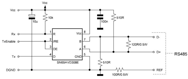
  • The 510 ohm pull up and pull down resistors are usually mounted on the master side. Theoretically it
    would be best to install it in the middle of your bus line. The 120 ohm termination resistor must always
    be used on distances greater than 1 meter and/or baud rates higher than 9600. It’s best to install it as a
    norm as noise and reflections will cause havoc on your communication once implemented in the field.
    The termination resistors should be mounted at both ends of the bus line. Please note that adding bias
    resistors will load the driver IC output. With the indicated values the max number of units on the bus
    line is limited to eight 12kΩ, sixteen 24kΩ, or thirty-two 48kΩ units.
    For further protection transient suppressors can be installed across the differential lines, from the Vcc to
    D+ and from GND to D-.!
    0_1491314128147_upload-f4c63383-2b9a-4f3d-bd48-1e25fcf9dc76


  • Google for simple Modbus Master dcouments (arduino forum)

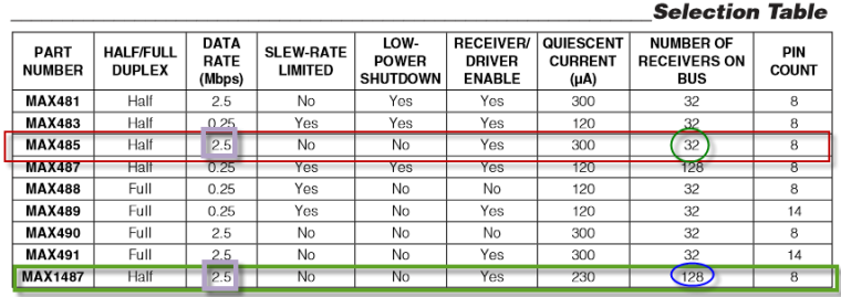
    The MAX485 is not the best RS485 chip because of it's own internal impedance.
    The chip in the diagram can be change by MAX485, MAX...
    0_1491314500978_upload-db69c9ce-43b6-430d-8807-74438ad83b96

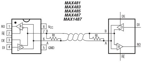
    https://datasheets.maximintegrated.com/en/ds/MAX1487-MAX491.pdf


  • FYI
    0_1491315316611_upload-40d28ad1-8ba3-4a11-aa7b-5bd1e84424d2


  • Hi, I'm building my home automation system and I have UTP cables cat5e in walls going to my wall switches. I have four cables, 5 nodes on one cable, 2 nodes on the second cable, and one node on 3rd and one 4th cable. 9 nodes. I know that the RS485 should be connected in parallel on single twisted pair but i cant change cables now cause my walls are painted etc.. So I have few problems, nodes stops working, i need to reset them few times, after few days the network stops to work and i start to search for an answers here. I changed numbers of SOH from 1 to 3 in 274 line of MyTransportRS485.cpp and now I think the network working better. I have 120ohm resistor in every node. You think that I should remove them ? Nodes are max 10 meters from the gateway so the cable lengths aren't so long.


  • @nofox
    If you have got one free pair of wires in cat5e cable, it is easy to convert your "star" topology to pure 485 bus topology with terminal resistors on both ends only.


  • Mod

    I think the 120Ohms resistor needs to go at the end of the cable, not on each node


  • @kimot I was thinking about that before I wrote here, and if nothing else can help I will convert star to bus.


  • @nofox it's what gohan stated, the 120ohm resistors should only put on the first and last node of you network. And you can only use a "bus" network topology for RS485.You should use the other wires of you Ethernet cable to accomplish this like kimot wrote.


  • Ok, so i switched my RS485 network to "bus". I desolder all of 120ohm resistors and have them only on both ends of the bus. RS485 to Ethernet gateway is in the middle of the wire. There are still some problems.. When I switching on the power and reading debug from gate I see that only 4 from 9 nodes are presenting. I need to reset other nodes manually to get them properly presented to the gateway. What am I doing wrong ? I need help I think.. Maybe its caused by the fact that all nodes powering on at the same time and there are many collisions on the RS485 bus ?? Maybe I should add some different delay() to setup part of my sketches to give, a time for every single node to present to the gateway ? Someone have successful working rs485 mysensors network here ?

    This is code for one of my nodes with buttons, relays and temperature sensor:

    #define MY_NODE_ID 8
    
    // Enable debug prints to serial monitor
    #define MY_DEBUG 
    
    // Enable RS485 transport layer
    #define MY_RS485
    
    // Define this to enables DE-pin management on defined pin
    #define MY_RS485_DE_PIN 2
    
    // Set RS485 baud rate to use
    #define MY_RS485_BAUD_RATE 9600
    
    #include <SPI.h>
    #include <MySensors.h>
    #include <Bounce2.h>
    #include <DallasTemperature.h>
    #include <OneWire.h>
    #include <OneButton.h>
    
    // define actions for OneButton function
    typedef enum {
      ACTION_OFF_1,  // set relay "OFF".
      ACTION_ON_1,   // set relay "ON"
      ACTION_OFF_2, 
      ACTION_ON_2
    }
    MyActions;
    
    MyActions nextAction_1 = ACTION_OFF_1;
    MyActions nextAction_2 = ACTION_OFF_2;
    
    // define Arduino I/O pins for relays
    #define RELAY_1  3 // Arduino Digital I/O pin number for first relay
    #define RELAY_2  5 // Arduino Digital I/O pin number for first relay
    #define RELAY_ON 1  // GPIO value to write to turn on attached relay
    #define RELAY_OFF 0 // GPIO value to write to turn off attached relay
    
    // configure parameters for 1Wire temp sensor
    #define COMPARE_TEMP 1
    #define ONE_WIRE_BUS 6
    #define MAX_ATTACHED_DS18B20 16
    
    // define CHILD IDs for relays and virtual multiaction click/doubleclick/longpress buttons
    #define CHILD_ID_11 11 // child id for first relay and first button single click 
    #define CHILD_ID_12 12 // child id for second relay and second button single click
    // #define CHILD_ID_13 13 // child id for first button single click (in this version not active because single click is attached directly to relay state)
    #define CHILD_ID_14 14 // child id for first button double click
    #define CHILD_ID_15 15 // child id for first button long press
    // #define CHILD_ID_16 16 // child id for second button single click (in this version not active because single click is attached directly to relay state)
    #define CHILD_ID_17 17 // child id for second button double click
    #define CHILD_ID_18 18 // child id for second button long press
    
    // define variables for temperature (and other) 1Wire Sensors
    long previousMillis = 0;
    long sensorInterval = 60000; // interval for temperature measurement 
    long HI_interval = 1000;
    OneWire oneWire(ONE_WIRE_BUS);
    DallasTemperature sensors(&oneWire);
    
    float lastTemperature[MAX_ATTACHED_DS18B20];
    int numSensors=0;
    bool recivedConfig = false;
    bool metric = true;
    
    // define Arduino Digital I/O pins for OneButton function
    OneButton BUTTON_1(7, true); // Arduino Digital I/O pin number for first physical button
    OneButton BUTTON_2(10, true); // Arduino Digital I/O pin number for second physical button
    
    bool V1_BUTTON_1; // set variable for virtual one click button 1
    bool V2_BUTTON_1; // set variable for virtual double click button 1
    bool V3_BUTTON_1; // set variable for virtual long press button 1
    
    bool V1_BUTTON_2; // set variable for virtual one click button 2
    bool V2_BUTTON_2; // set variable for virtual one click button 2
    bool V3_BUTTON_2; // set variable for virtual one click button 2
    
    
    bool state1; // variable for RELAY_1 states 
    bool state2; // variable for RELAY_2 states 
    
    void before()
    {    
    
     sensors.begin();
    
    }
    
    //define messages for diferent type of sensors CHILD_IDs used
    MyMessage msg0(0,V_TEMP); // temperature sensor message
    MyMessage msg11(CHILD_ID_11, V_LIGHT); // first relay & single click message
    MyMessage msg12(CHILD_ID_12, V_LIGHT); // second relay & single click message
    
    // MyMessage msg13(CHILD_ID_13, V_LIGHT); // button 1 Single click
    MyMessage msg14(CHILD_ID_14, V_LIGHT); // button 1 Double click
    MyMessage msg15(CHILD_ID_15, V_LIGHT); // button 1 Long press
    
    // MyMessage msg16(CHILD_ID_16, V_LIGHT); // button 2 Single click
    MyMessage msg17(CHILD_ID_17, V_LIGHT); // button 2 Dobule click
    MyMessage msg18(CHILD_ID_18, V_LIGHT); // button 2 Long press
    
    void setup()
    {
    
    digitalWrite(RELAY_1, RELAY_OFF); // Set first relay state and pin mode
     pinMode(RELAY_1, OUTPUT);
    
    state1 = loadState(CHILD_ID_11);  // Set relay to last known state (using eeprom storage)
     digitalWrite(RELAY_1, state1?RELAY_ON:RELAY_OFF);
    
    digitalWrite(RELAY_2, RELAY_OFF); // Set second relay state and pin mode 
     pinMode(RELAY_2, OUTPUT);
    
    state2 = loadState(CHILD_ID_12);  // Set relay to last known state (using eeprom storage)
     digitalWrite(RELAY_2, state2?RELAY_ON:RELAY_OFF); 
    
     
    // sending states of relays after node bootup
    send(msg11.set(state1));
    send(msg12.set(state2));
    
    // attaching physical BUTTON_1 to OneButton function actions
    BUTTON_1.attachClick(singleclick_BUTTON_1);
    BUTTON_1.attachDoubleClick(doubleclick_BUTTON_1);
    BUTTON_1.attachLongPressStop(longpress_BUTTON_1);
    // attaching physical BUTTON_2 to OneButton function actions
    BUTTON_2.attachClick(singleclick_BUTTON_2);
    BUTTON_2.attachDoubleClick(doubleclick_BUTTON_2);
    BUTTON_2.attachLongPressStop(longpress_BUTTON_2);
    // setup for temperature sensor
    sensors.setWaitForConversion(false);
    
    }
    
    void presentation()
    {
        sendSketchInfo("pokoiczek_puszka_1", "1.0");
    
        numSensors = sensors.getDeviceCount();
    
      // Present all sensors to controller
      for (int i=0; i<numSensors && i<MAX_ATTACHED_DS18B20; i++) {   
         present(i, S_TEMP);
      }
    
        present(CHILD_ID_11, S_LIGHT);
        present(CHILD_ID_12, S_LIGHT);
        
        // present(CHILD_ID_13, S_LIGHT);
        present(CHILD_ID_14, S_LIGHT);
        present(CHILD_ID_15, S_LIGHT);
        
        // present(CHILD_ID_16, S_LIGHT);
        present(CHILD_ID_17, S_LIGHT);
        present(CHILD_ID_18, S_LIGHT);
        
    }
    
    
    void loop()
    {
    
      temperatureCheck(); // tmperature check function
    
      // states for nextAction of OneButton function
      if(state1 == HIGH)
        {
          nextAction_1 = ACTION_OFF_1;
        }
        else 
        {
          nextAction_1 = ACTION_ON_1;
        }
    
      BUTTON_1.tick();  // reading state of first physical button 
      
      if(state2 == HIGH)
        {
          nextAction_2 = ACTION_OFF_2;
        }
        else 
        {
          nextAction_2 = ACTION_ON_2;
        }  
      
      BUTTON_2.tick(); // // reading state of second physical button 
      
    }
    
    void singleclick_BUTTON_1()
     {
      if (nextAction_1 == ACTION_OFF_1 )
        {
          nextAction_1 = ACTION_ON_1;
          send(msg11.set(HIGH?false:true), true);
        }
      else
        {
        nextAction_1 = ACTION_OFF_1;
        send(msg11.set(LOW?false:true), true);
        }
      // send(msg13.set(LOW ? 1 : 0));
      // send(msg13.set(HIGH ? 1 : 0));
     }
    
    void doubleclick_BUTTON_1()
    {
       send(msg14.set(LOW ? 1 : 0));
       send(msg14.set(HIGH ? 1 : 0));
    }
    
    void longpress_BUTTON_1()
    {
       send(msg15.set(LOW ? 1 : 0));
       send(msg15.set(HIGH ? 1 : 0));
    }
    
    void singleclick_BUTTON_2()
    {
       
       if (nextAction_2 == ACTION_OFF_2 )
        {
          nextAction_2 = ACTION_ON_2;
          send(msg12.set(HIGH?false:true), true);
        }
      else
        {
        nextAction_2 = ACTION_OFF_2;
        send(msg12.set(LOW?false:true), true);
        }
       
      // send(msg16.set(LOW ? 1 : 0));
      // send(msg16.set(HIGH ? 1 : 0));
    }
    
    void doubleclick_BUTTON_2()
    {
       send(msg17.set(LOW ? 1 : 0));
       send(msg17.set(HIGH ? 1 : 0));
    }
    
    void longpress_BUTTON_2()
    {
       send(msg18.set(LOW ? 1 : 0));
       send(msg18.set(HIGH ? 1 : 0));
    }
    
    void temperatureCheck()
    {
     unsigned long currentMillis = millis();
     if(currentMillis - previousMillis > sensorInterval)
      {
        previousMillis = currentMillis;
        
      // Fetch temperatures from Dallas sensors
      sensors.requestTemperatures();
      // query conversion time and sleep until conversion completed
      int16_t conversionTime = sensors.millisToWaitForConversion(sensors.getResolution());
      // sleep() call can be replaced by wait() call if node need to process incoming messages (or if node is repeater)
      wait(conversionTime);
      // Read temperatures and send them to controller 
      for (int i=0; i<numSensors && i<MAX_ATTACHED_DS18B20; i++) {
        // Fetch and round temperature to one decimal
        float temperature = static_cast<float>(static_cast<int>((getControllerConfig().isMetric?sensors.getTempCByIndex(i):sensors.getTempFByIndex(i)) * 10.)) / 10.;
        // Only send data if temperature has changed and no error
        #if COMPARE_TEMP == 1
        if (lastTemperature[i] != temperature && temperature != -127.00 && temperature != 85.00) {
        #else
        if (temperature != -127.00 && temperature != 85.00) {
        #endif
          // Send in the new temperature
          send(msg0.setSensor(i).set(temperature,1));
          // Save new temperatures for next compare
          lastTemperature[i]=temperature;
        }
      }
      
    }
    
    }
    
    void receive(const MyMessage &message)
    {
      if (message.type == V_STATUS && message.sensor == 11) {
        // Change relay state
        state1 = message.getBool();
        digitalWrite(RELAY_1, state1?RELAY_ON:RELAY_OFF);
        // Store state in eeprom
        saveState(CHILD_ID_11, state1);
        
       // send(msg11.set(state1));
    
         // Write some debug info
        Serial.print("Incoming change for sensor:");
        Serial.print(message.sensor);
        Serial.print(", New status: ");
        Serial.println(message.getBool());
      }
      else if (message.type == V_STATUS && message.sensor == 12) {
    
        state2 = message.getBool();
        digitalWrite(RELAY_2, state2?RELAY_ON:RELAY_OFF);
    
        saveState(CHILD_ID_12, state2);
    
       // send(msg12.set(state2));
        
        // Write some debug info
        Serial.print("Incoming change for sensor:");
        Serial.print(message.sensor);
        Serial.print(", New status: ");
        Serial.println(message.getBool());
      }
    }
    

    I'm using OneButton library to get different actions when i'm clicking once, twice and holding buttons.


  • Nofox,

    1. The 510 ohm pull up and pull down resistors (between A (D+) and 5V / between B (D-) and ground) are usually mounted on the master side (which is your gateway). Theoretically it would be best to install it in the middle of your bus line.
    2. check if your power supply has enough power to feed all your nodes
    3. check that all the ground lines of your boards are connected with each other.


  • @ArduiSens Thanks for your reply! I have found few post here on MYS Forum about biasing rs485 line with pull up and pull down resistors and I will try to do this tomorrow. I'm using standard rs485 module from aliexpress on the gateway side. There are pullups and pulldowns there but they are two 10k resistors, I will change them to 510 as you mentioned.
    All of my wired sensors, gateway and RPi are powered form 10A buffered power supply. I've checked voltage on every node. I have 5.25V on power supply pins in the middle of the line and 5.21 on both ends of line. I'm using one twisted pair for Vcc and one for GND. The bus is about 15 meter long form one end to another.
    As I mentioned above all of nodes are supplied from one power supply so the grounds are all connected.


  • Hello again. I've soldered this two pull-ups resistors like @ArduiSens wrote before. Now I think the network works much much better but after 24 hours of using something hangs and i can't turn of the light with buttons and with OpenHab also. I think the gateway freezing because after I reset only gateway all starts to work normal when i'm pressing wall switches. I need to reboot controller because after gateway reset OpenHab won't communicate with the gateway... Please take a look at my gateway sketch:

    // Enable debug prints to serial monitor
    #define MY_DEBUG
    
    // Enable and select radio type attached
    // #define MY_RADIO_NRF24
    // #define MY_RADIO_RFM69
    #define MY_NODE_ID 0
    // Enable RS485 transport layer
    #define MY_RS485
    
    // Define this to enables DE-pin management on defined pin
    #define MY_RS485_DE_PIN 2
    
    // Set RS485 baud rate to use
    #define MY_RS485_BAUD_RATE 9600
    
    // #define MY_GATEWAY_MQTT_CLIENT
    
    // Enable gateway ethernet module type
    #define MY_GATEWAY_W5100
    
    // W5100 Ethernet module SPI enable (optional if using a shield/module that manages SPI_EN signal)
    // #define MY_W5100_SPI_EN 4
    
    // Enable Soft SPI for NRF radio (note different radio wiring is required)
    // The W5100 ethernet module seems to have a hard time co-operate with
    // radio on the same spi bus.
    #if !defined(MY_W5100_SPI_EN) && !defined(ARDUINO_ARCH_SAMD)
    #define MY_SOFTSPI
    #define MY_SOFT_SPI_SCK_PIN 14
    #define MY_SOFT_SPI_MISO_PIN 16
    #define MY_SOFT_SPI_MOSI_PIN 15
    #endif


    // When W5100 is connected we have to move CE/CSN pins for NRF radio
    // #ifndef MY_RF24_CE_PIN
    // #define MY_RF24_CE_PIN 5
    // #endif
    // #ifndef MY_RF24_CS_PIN
    // #define MY_RF24_CS_PIN 6
    // #endif
    
    // Enable to UDP
    // #define MY_USE_UDP
    
    #define MY_IP_ADDRESS 192,168,0,66   // If this is disabled, DHCP is used to retrieve address
    // Renewal period if using DHCP
    //#define MY_IP_RENEWAL_INTERVAL 60000
    // The port to keep open on node server mode / or port to contact in client mode
    #define MY_PORT 5003
    // Controller ip address. Enables client mode (default is "server" mode).
    // Also enable this if MY_USE_UDP is used and you want sensor data sent somewhere.
    //#define MY_CONTROLLER_IP_ADDRESS 192, 168, 0, 70
    
    // The MAC address can be anything you want but should be unique on your network.
    // Newer boards have a MAC address printed on the underside of the PCB, which you can (optionally) use.
    // Note that most of the Ardunio examples use  "DEAD BEEF FEED" for the MAC address.
    #define MY_MAC_ADDRESS 0xDE, 0xAD, 0xBE, 0xEF, 0xFE, 0xED
    
    // Set this node's subscribe and publish topic prefix
    // #define MY_MQTT_PUBLISH_TOPIC_PREFIX "mygateway1-out"
    // #define MY_MQTT_SUBSCRIBE_TOPIC_PREFIX "mygateway1-in"
    
    // Set MQTT client id
    // #define MY_MQTT_CLIENT_ID "mysensors-1"
    
    // Enable these if your MQTT broker requires usenrame/password
    //#define MY_MQTT_USER "username"
    //#define MY_MQTT_PASSWORD "password"
    
    // Enable inclusion mode
    // #define MY_INCLUSION_MODE_FEATURE
    // Enable Inclusion mode button on gateway
    //#define MY_INCLUSION_BUTTON_FEATURE
    // Set inclusion mode duration (in seconds)
    // #define MY_INCLUSION_MODE_DURATION 60
    // Digital pin used for inclusion mode button
    //#define MY_INCLUSION_MODE_BUTTON_PIN  3
    
    // Set blinking period
    #define MY_DEFAULT_LED_BLINK_PERIOD 300
    
    // Flash leds on rx/tx/err
    // Uncomment to override default HW configurations
    //#define MY_DEFAULT_ERR_LED_PIN 7  // Error led pin
    //#define MY_DEFAULT_RX_LED_PIN  8  // Receive led pin
    //#define MY_DEFAULT_TX_LED_PIN  9  // Transmit led pin
    
    
    #if defined(MY_USE_UDP)
    #include <EthernetUdp.h>
    #endif
    #include <Ethernet.h>
    #include <MySensors.h>
    
    
    void setup()
    {
    }
    
    void loop()
    {
    }
    

  • Mod

    @nofox why are you using soft SPI? You don't have a nrf24 radio


  • @gohan I'm using soft SPI ? Where ? I taught that there are

    #if !defined(MY_W5100_SPI_EN) && !defined(ARDUINO_ARCH_SAMD)
    #define MY_SOFTSPI
    #define MY_SOFT_SPI_SCK_PIN 14
    #define MY_SOFT_SPI_MISO_PIN 16
    #define MY_SOFT_SPI_MOSI_PIN 15
    #endif
    

    so when #define MY_W5100_SPI_EN 4 is commented I'm using hardware SPI ? What should i change than ? Comment the whole #if .... part ??


  • Mod

    Forget it, I was on mobile and couldn't see well the code. Do you have IDE, boards definitions up to date? Did you try latest version of mysensors in development branch?


  • @gohan I have IDE 1.6.11 and boards definition 1.6.11 because on newer boards definition I've got boot loop on gateway. I'm using 2.1.1 MySensors library. Maybe I should mention that I can ping my gateway without any problems, only rs485 part seems not responding..


  • Hello again. After a week of thinking and hard work i finally got RS485 network working very close to what I want. I've done everything like it was mentioned here before. Fully bus-like network, termination only on both ends of line and pull-up and pull-down on the gateway. I also change MySensors library to newest 2.1 beta branch. All nodes working very good for last month but some times one node hanging and I can't control it via OpenHab or built in switch. I don't know what cause this behavior. I turn on watchdog timers in every nodes and theoretically when node hangs, watchdog should reboot arduino after 8 seconds. Practically it won't reboot my node.. It seems like the node don't really hangs but the communication stops.. Is it possible that one node can loose connection while other nodes on the same bus/wires working like a charm ?


  • @nofox The problem you describe sounds pretty similar to my observations in this post.
    There are also some suggestions how to solve this kind of trouble you may apply.


  • Hi! It’s me again. I want to precise one thing. Are there anyone here who have succesful working RS485 network without any issues? We are talking here about issues but maybe someone have fully working sensors network?


  • If some node hangs what happens if you recycle the power of rs485 transceiver only?
    I'm just thinking could it be the protection of max485 that kicks in if there is two nodes sending exactly the same time.


  • Hi! My problem still exist. I switched to newest MySensors Library and to HWSERIAL and some nodes acts the same as before... Now i'm thinking that maybe its related to DE_PIN 2 ?? Someone tried to switch to other pin for Enable function for RS485 ?? Now after almost a year I'm thinking about changing my transmission from wired RS485 to wireless nRF.. I choose RS485 because of its stability (thats what I taught over a year ago ). Now I think that RS485 its a piece of garbage..


  • Hi! I think I came up with the solution for all our problems but I don't know if it is worth and possible at all. The thing is that RS485 isn't a multimaster bus, thats what we all know. So the best option is to turn the gateway in to master and all other nodes to slaves. I'm thinking if there are any possibilities to make the gateway to ask nodes in the order one by one for its states (child states). The nodes can only talk to the gateway when the gateway ask for their states. This process should take place in endless loop in the highest possible speed (depending on the count of nodes in the network). I think that in this option the baud rate matters, cause higher baud rates makes the time of a single loop shorter minimizing the delay that may occur in the networks with many nodes. Maybe I'm reinventing the wheel now and this type of transmission needs to rewrite all MySensors protocols..


  • @nofox absolutely that is one of the problems. Polling as you describe could be a fix, another is having each node listen before transmitting, there is a (not mysensors) library that does that, CAN bus( a mutli master 485 comaptible bus) is another option. I think that running a common ground to all the rs485 adapters is also wise. This is all in theory as I havent wired up my home yet....


  • @wallyllama

    another is having each node listen before transmitting

    How would you describe this functionality in MySensors rs485 code?
    https://github.com/mysensors/MySensors/blob/f5ed26c778c18107d1516bd86704f8c8f99ff571/hal/transport/RS485/MyTransportRS485.cpp#L246
    If I'm reading the code correctly it is exactly reading the bus and making sure no other node is sending before sending anything.
    The place where collision can happen is those 5 microseconds what the node is waiting to get driver tx enabled pin up.

    So the collision avoidance is already there. So what MyS R485 transport is missing is collision detection and recovery from collision.

    CAN bus( a mutli master 485 comaptible bus) is another option.

    Its disadvantage is small payload size.

    @nofox Its quite like how the Modbus works. By polling.
    I think there is some better ways to do that. Check these out from google:

    • RS-485 Token ring
    • uLAN
    • RS-485 RRP (Round Robin Protocol)
    • CSMA/CA


  • I think you have found most everything that I have. Something akin to csmacd is what I was thinking. Listen, transmit, back off for random time if a collision still happens. Of course full duplex rs485 is another option, hard to find off the shelf modules.

    I think this is the library I had found before.
    https://github.com/MichaelJonker/HardwareSerialRS485/wiki


  • https://github.com/dukelec/cdbus_doc
    This one has some is interesting, not sure if it does multi master or not. There are a few projects that seem to do multimaster/collision avoidance, the trick it to find one with low enough overhead and automatically retransmits if there is a failure, and for this project isolates this enough that my sensors doesnt need restructuring.

    Good wiring is crucial so you can use higher speeds. The common ground wire in addition to the differential signals seems almost required.


  • But PJON uses completely sw bit by bit sending or HW sending with bad bus arbitration.

    My idea - combination CAN bus like arbitration and UART message sending.
    With ACK possibility.

    Time T1 ( two bytes send time for example )

    Node sends message and waits T1 time for ACK.
    Receiving node must send ACK within T1 interval.

    Node, witch needs send message listens bus.
    BUT not by HW UART or SoftwareSerial - use directo IO operation.
    If recognize bus free time greater then T1, it start sending its own ID.
    BUT again not by HW UART or SoftwareSerial - but bit by bit by direct IO pin operation.
    And listen if bit I am sending is bit I am receiving.
    If not - it means, that other node with higher priority ( lower ID ) is sending - then immediately stop sending other bit and wait for next bus free T1 interval.
    If yes - bus is free for me end send my message normally by UART ( HW or SW, maybe with 9 bit addressing support - time less than T1 between characters allowed).
    Wait max T1 time for ACK.

    CAN bus driver usage TJA 1050 or MCP2551 - no DE RE pins.


  • I have the problem that I always get this error: !TSM:FPAR:NO REPLY

    Once it worked briefly yesterday.

    What have I tried everything?
    All hardware exchanged - without success.

    Now I have just written two small scripts that send RS485 back and forth. without problems. So wiring has to fit. I spent then in the serial montior the data which the node sends me, there comes some. Then I once tried to display the data that sends the GW, because nothing comes.

    Does anyone have an idea why my GW does not answer?


  • Mod

    @andreas-sieber could you post the debug output from the node and the gateway?


  • | / |_ / | ___ _ __ ___ ___ _ __ ___
    | |/| | | | _
    \ / _ \ _ \/ __|/ _ \|
    _/ __|
    | | | | |
    | || | / | | _ \ _ | | _
    |
    | |
    |_
    , |/ ___|| ||/_/|| |/
    |
    __/ 2.3.0-alpha

    17 MCO:BGN:INIT NODE,CP=RSNNA---,VER=2.3.0-alpha
    26 TSM:INIT
    27 TSF:WUR:MS=0
    29 TSM:INIT:TSP OK
    30 TSM:FPAR
    49 TSF:MSG:SEND,255-255-255-255,s=255,c=3,t=7,pt=0,l=0,sg=0,ft=0,st=OK:
    2056 !TSM:FPAR:NO REPLY
    2058 TSM:FPAR
    2075 TSF:MSG:SEND,255-255-255-255,s=255,c=3,t=7,pt=0,l=0,sg=0,ft=0,st=OK:
    4083 !TSM:FPAR:NO REPLY
    4085 TSM:FPAR
    4103 TSF:MSG:SEND,255-255-255-255,s=255,c=3,t=7,pt=0,l=0,sg=0,ft=0,st=OK:
    6111 !TSM:FPAR:NO REPLY
    6113 TSM:FPAR
    6130 TSF:MSG:SEND,255-255-255-255,s=255,c=3,t=7,pt=0,l=0,sg=0,ft=0,st=OK:

    0;255;3;0;9;0 MCO:BG
    0;255;3;0;9;29 MCO:BGN:INIT OK,TSP=1
    0;255;3;0;9;0 MCO:BGN:INIT GW,CP=RSNGA---,VER=2.3.0-alpha
    0;255;3;0;9;5 TSM:INIT
    0;255;3;0;9;7 TSF:WUR:MS=0
    0;255;3;0;9;9 TSM:INIT:TSP OK
    0;255;3;0;9;12 TSM:INIT:GW MODE
    0;255;3;0;9;15 TSM:READY:ID=0,PAR=0,DIS=0
    0;255;3;0;9;18 MCO:REG:NOT NEEDED
    0;255;3;0;14;Gateway startup complete.
    0;255;0;0;18;2.3.0-alpha
    0;255;3;0;9;22 MCO:BGN:STP
    0;255;3;0;9;29 MCO:BGN:INIT OK,TSP=1


  • Mod

    why don't you use the stable 2.2? Anyway the node is missing the my_node_id define and second it seems the gateway isn't receiving anything, so I guess there is something very wrong in communication


  • in the 2.2 the same problem, i have now updagradet to alpha.

    When you have a solution on 2.2 i will downgrade. no problem!

    Guys you are good! I had set the mynodeid. But befor i include the my sensors.. that's the mistake..

    hour of hour to search... thx!


  • Is it possible, or will it be possible to build a combination between wired and wireless nodes?


  • Mod

    one network, one gateway


  • I just trying to work with examples but my node always transmitting some piece of shit from hardware serial:

     
     __  __       ____
    |  \/  |_   _/ ___|  ___ _ __  ___  ___  _ __ ___
    | |\/| | | | \___ \ / _ \ `_ \/ __|/ _ \| `__/ __|
    | |  | | |_| |___| |  __/ | | \__ \  _  | |  \__ \
    |_|  |_|\__, |____/ \___|_| |_|___/\___/|_|  |___/
            |___/                      2.3.0
    
    16 MCO:BGN:INIT NODE,CP=RSNNA---,VER=2.3.0
    25 TSM:INIT
    26 TSF:WUR:MS=0
    28 TSM:INIT:TSP OK
    29 TSF:SID:OK,ID=5
    31 TSM:FPAR
    ⸮X⸮⸮w34 TSF:MSG:SEND,5-5-255-255,s=255,c=3,t=7,pt=0,l=0,sg=0,ft=0,st=OK:
    2041 !TSM:FPAR:NO REPLY
    2043 TSM:FPAR
    ⸮X⸮⸮w2045 TSF:MSG:SEND,5-5-255-255,s=255,c=3,t=7,pt=0,l=0,sg=0,ft=0,st=OK:
    4054 !TSM:FPAR:NO REPLY
    4056 TSM:FPAR
    ⸮X⸮⸮w4058 TSF:MSG:SEND,5-5-255-255,s=255,c=3,t=7,pt=0,l=0,sg=0,ft=0,st=OK:
    6066 !TSM:FPAR:NO REPLY
    6068 TSM:FPAR
    ⸮X⸮⸮w6070 TSF:MSG:SEND,5-5-255-255,s=255,c=3,t=7,pt=0,l=0,sg=0,ft=0,st=OK:
    8078 !TSM:FPAR:FAIL
    8079 TSM:FAIL:CNT=1
    8081 TSM:FAIL:DIS
    8083 TSF:TDI:TSL
    

    From software serial too

    ⸮X⸮⸮w
    ⸮X⸮⸮w
    ⸮X⸮⸮w
    ⸮X⸮⸮w
    

    Consequently the gateway can't find any device.
    I have tried also with RS485 with different baudrate. Finally I just connect my USB TTL directly to ouput pins, but always same result.
    How to fix it?


  • @Pavel-Polititsky
    To me this looks like you mixed between-node communication (RS485) with debug output (and maybe also serial output of the gw).
    The corresponding serial interface for RS485 should be dedicated to RS485 exclusively.


  • Hi,
    first of I have to thank you for your effort on this project! It helped me a lot.
    In my house I would like to build 2 networks, one with serial gateway with RF24 for ground floor and outside. Second will be in cellar and I was thinking about Ethernet gateway (W5500) but sensors will be connected via RS485. Do you have code for that? On the video it looks like that in the box on right side it is something like this.


  • I have exactly the same problem. Has anyone managed to run it.


  • | / |_ / | ___ _ __ ___ ___ _ __ ___
    | |/| | | | _
    \ / _ \ _ \/ __|/ _ \|
    _/ __|
    | | | | |
    | || | / | | _ \ _ | | _
    |
    | |
    |_
    , |/ ___|| ||/_/|| |/
    |
    __/ 2.3.1

    16 MCO:BGN:INIT NODE,CP=RSNNA---,REL=255,VER=2.3.1
    26 TSM:INIT
    27 TSF:WUR:MS=0
    28 TSM:INIT:TSP OK
    30 TSM:FPAR
    56 TSF:MSG:SEND,255-255-255-255,s=255,c=3,t=7,pt=0,l=0,sg=0,ft=0,st=OK:
    2063 !TSM:FPAR:NO REPLY
    2065 TSM:FPAR
    2082 TSF:MSG:SEND,255-255-255-255,s=255,c=3,t=7,pt=0,l=0,sg=0,ft=0,st=OK:
    4090 !TSM:FPAR:NO REPLY
    4092 TSM:FPAR
    4110 TSF:MSG:SEND,255-255-255-255,s=255,c=3,t=7,pt=0,l=0,sg=0,ft=0,st=OK:
    6118 !TSM:FPAR:NO REPLY
    6120 TSM:FPAR
    6137 TSF:MSG:SEND,255-255-255-255,s=255,c=3,t=7,pt=0,l=0,sg=0,ft=0,st=OK:
    8146 !TSM:FPAR:FAIL
    8147 TSM:FAIL:CNT=1
    8150 TSM:FAIL:DIS
    8152 TSF:TDI:TSL
    18154 TSM:FAIL:RE-INIT
    18156 TSM:INIT
    18157 TSM:INIT:TSP OK
    18159 TSM:FPAR
    18178 TSF:MSG:SEND,255-255-255-255,s=255,c=3,t=7,pt=0,l=0,sg=0,ft=0,st=OK:
    20186 !TSM:FPAR:NO REPLY
    20188 TSM:FPAR
    20206 TSF:MSG:SEND,255-255-255-255,s=255,c=3,t=7,pt=0,l=0,sg=0,ft=0,st=OK:
    22213 !TSM:FPAR:NO REPLY
    22215 TSM:FPAR
    22234 TSF:MSG:SEND,255-255-255-255,s=255,c=3,t=7,pt=0,l=0,sg=0,ft=0,st=OK:
    24241 !TSM:FPAR:NO REPLY
    24243 TSM:FPAR
    24261 TSF:MSG:SEND,255-255-255-255,s=255,c=3,t=7,pt=0,l=0,sg=0,ft=0,st=OK:
    26268 !TSM:FPAR:FAIL
    26269 TSM:FAIL:CNT=2
    26271 TSM:FAIL:DIS
    26273 TSF:TDI:TSL


  • Mod

    @giebek could you describe the problem, what your setup looks like, and what you have tried so far to troubleshoot it? There are 137 posts in this thread so it is a bit hard to figure out which problem you are referring to.


  • @GieBek

    6137 TSF:MSG:SEND,255-255-255-255,s=255,c=3,t=7,pt=0,l=0,sg=0,ft=0,st=OK:

    Imo this indicates your node doesn't have a NodeID yet. When using RS485 you have to assign the ID's manually in the sketch, auto doesn't work... (e.g. #define MY_NODE_ID 123)


  • Thanks for the answers.
    And even more thanks to the rejoe2

    #define MY_NODE_ID 123

    it helped 100% the transmission went, domoticz sees children.


  • hello MySensors friends,

    I am currently making a node based on an arduino Mega 2560 with transport via RS-485, the build page says that we should use the MEGA pin 46 & 48, I was wondering if I would like a reference for this. in the sketch.
    Second question; can I use pin 47 for the DE pin with:

    #define MY_RS485_DE_PIN 47
    

    I haven't tested anything yet, so actually I just ask a lazy question 😉


  • Hello, I would like to better understand the concept here. It sounds like we still need a gateway connected to a controller (serial, Ethernet, WiFi, etc.) but the interface between gateway and multiple nodes is over wired RS485 serial interface. Please confirm. Thank you for your great efforts!


  • @apl2017 Yes, also for RS485 variant you'll need a gateway. Only the communication between the gateway and the other nodes is handled over RS485, connected to a second (typically software) serial interface (for remote nodes, you may just use the hardware serial interface to connect the RS485 transceiver, if you do not need debug output; but imo this option is not recommended for beginners).


  • @dzjr said in 💬 Building a wired RS485 sensor network:

    hello MySensors friends,

    I am currently making a node based on an arduino Mega 2560 with transport via RS-485, the build page says that we should use the MEGA pin 46 & 48, I was wondering if I would like a reference for this. in the sketch.
    Second question; can I use pin 47 for the DE pin with:

    #define MY_RS485_DE_PIN 47
    

    I haven't tested anything yet, so actually I just ask a lazy question 😉

    I have it working, so you don't have to adjust anything for a Mega, and pin 47 for DE also works!


  • Hi,
    in a node how many children can put rs-485
    thanks good work


  • and it can have blockages if there are sensors that function or even time
    thanks


  • @zrom69

    I have a node with 52 child id's on a Arduino mega,

    Arnout 22 of Them receiving data (relay & dimmers) and the rest are sending data, binary, temp/hum, soil moisture and analog data.

    Not all the nodes are in use, but i see the data in domoticz.

    I dont know how manny childs you want to use, for me 52 on one node are very mutch.


  • thank you for your reply
    at least 10 children in node and 30 nodes


  • @dzjr
    thank you for your reply
    at least 10 children in node and 30 nodes
    @dzjr


Log in to reply
 

Suggested Topics

  • 3
  • 109
  • 347
  • 2
  • 10
  • 110

1
Online

11.2k
Users

11.1k
Topics

112.5k
Posts