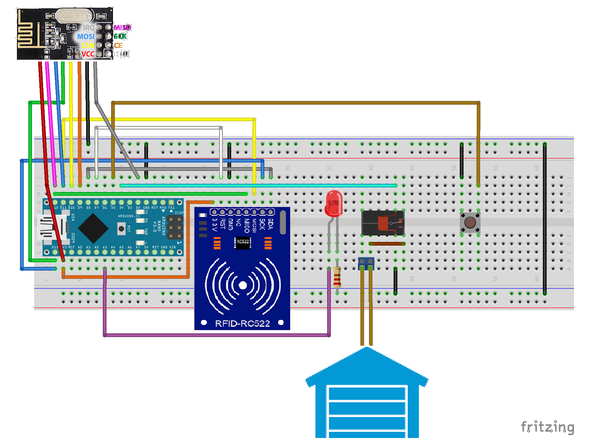
This sketch is to open a Garage door with an mifare RIFD-tag
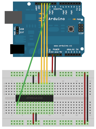
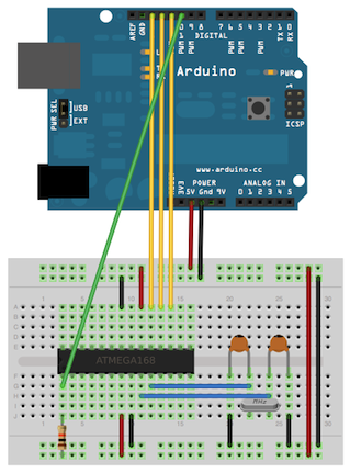
For an Arduino Nano v3 wiring :
- rf24l01+ as descibed on the MySensors website
- MFRC522 reader/writer as described above EXCEPT for pin D9 and D10: connect RST i.s.o. pin D9 to pin D7 and connect SDA(SS) i.s.o. pin D10 to pin D8
- LED with 470ohm resistor between GMD and pin A3
- push button between GND and pin D5
- 5v relays coil between GND and pin D4 -> switch pins of the relays should be connected in parallel with your garage door push button.
Features:
- This project can record up to 18 RFID-"tags"
- These card IDs are stored in to EEPROM by keeping them next to the RFID reader when the system in program mode. (Slow blinking LED) When a card is accepted as new card the LED will blink fast for a short time.
- To keep the master-tags (choose your own) next to the RFID reader when pressing the push button. To clear all cards (except the master card) press the push button in program mode for 6 seconds. The LED will now fast blink for a couple of seconds.
- Your garage your can be opened by keep a registered RFID tag next to the reader or by clicking the open icon on lock node presented by this plugin.
- By by-passing the alarm node presented by this plug in the RFID will be temporarily disabled.
- When an incorrect (not registered) RFID tag is scanned the alarm is triggered to detect illegal scan attempts
Used RFID reader can be found here:
The Sketch code:
/*
 * ----------------------------------------------------------------------------
 * This is a MFRC522 library example; see https://github.com/miguelbalboa/rfid
 * for further details and other examples.
 *
 * NOTE: The library file MFRC522.h has a lot of useful info. Please read it.
 *
 * Released into the public domain.
 * ----------------------------------------------------------------------------
 * Example sketch/program showing how to read data from a PICC (that is: a RFID
 * Tag or Card) using a MFRC522 based RFID Reader on the Arduino SPI interface.
 *
 * When the Arduino and the MFRC522 module are connected (see the pin layout
 * below), load this sketch into Arduino IDE then verify/compile and upload it.
 * To see the output: use Tools, Serial Monitor of the IDE (hit Ctrl+Shft+M).
 * When you present a PICC (that is: a RFID Tag or Card) at reading distance
 * of the MFRC522 Reader/PCD, the serial output will show the ID/UID, type and
 * any data blocks it can read. Note: you may see "Timeout in communication"
 * messages when removing the PICC from reading distance too early.
 *
 * If your reader supports it, this sketch/program will read all the PICCs
 * presented (that is: multiple tag reading). So if you stack two or more
 * PICCs on top of each other and present them to the reader, it will first
 * output all details of the first and then the next PICC. Note that this
 * may take some time as all data blocks are dumped, so keep the PICCs at
 * reading distance until complete.
 *
 * Typical pin layout used:
 * -----------------------------------------------------------------------------------------
 *             MFRC522      Arduino       Arduino   Arduino    Arduino          Arduino
 *             Reader/PCD   Uno           Mega      Nano v3    Leonardo/Micro   Pro Micro
 * Signal      Pin          Pin           Pin       Pin        Pin              Pin
 * -----------------------------------------------------------------------------------------
 * RST/Reset   RST          9             5         D9         RESET/ICSP-5     RST
 * SPI SS      SDA(SS)      10            53        D10        10               10
 * SPI MOSI    MOSI         11 / ICSP-4   51        D11        ICSP-4           16
 * SPI MISO    MISO         12 / ICSP-1   50        D12        ICSP-1           14
 * SPI SCK     SCK          13 / ICSP-3   52        D13        ICSP-3           15
 */

/*
 RFID Garagedoor opener by Bart Eversdijk

 This sketch is to open a Garage door with an mifare RIFD-tag

  For an Arduino Nano v3
  Connection wiring :
    - nrf24l01+ as descibed on the MySensors website
    - MFRC522 reader/writer as described above EXCEPT for pin D9 and D10:  connect RST i.s.o. pin D9 to pin D7 and connect SDA(SS) i.s.o. pin D10 to pin D8
    - LED with 470ohm resistor between GMD and pin A3
    - push button between GND and pin D5
    - 5v relays coil between GND and  pin D4 -> switch pins of the relays should be connected in parallel with your garage door push button.

  Features:
  This project can record up to 18 RFID-"tags"
  These card IDs are stored in to EEPROM by keeping them next to the RFID reader when the system in program mode. (Slow blinking LED) When a card is accepted as new card the LED will blink fast for a short time.
  To keep the master-tags (choose your own) next to the RFID reader when pressing the push button. To clear all cards (except the master card) press the push button in program mode for 6 seconds. The LED will now fast blink for a couple of seconds.

  Your garage your can be opened by keep a registered RFID tag next to the reader or by clicking the open icon on lock node presented by this plugin.
  By by-passing the alarm node presented by this plug in the RFID will be temporarily disabled.
  When an incorrect (not registered) RFID tag is scanned the alarm is triggered to detect illegal scan attempts

*/

#include <SPI.h>
#include <MFRC522.h>
#include <MySensor.h>
#include <Bounce2.h>

#define RF_INIT_DELAY   125
#define ONE_SEC         1000
#define MAX_CARDS       18
#define PROG_WAIT       10
#define HEARTBEAT       10
#define BAUD            115200

/*Pin definitions*/
#define LED_PIN         A3
#define GARAGEPIN       4
#define SWITCH_PIN      5
#define RST_PIN		7		//  MFRC
#define SS_PIN		8		//  MFRC

MFRC522      mfrc522(SS_PIN, RST_PIN);	// Create MFRC522 instance
MFRC522::Uid olduid;
MFRC522::Uid masterkey = { 10, {0,0,0,0, 0,0,0,0, 0,0 },  0 };

byte       countValidCards  = 0;
MFRC522::Uid validCards[MAX_CARDS];

void       ShowCardData(MFRC522::Uid* uid);
bool       sameUid(MFRC522::Uid* old, MFRC522::Uid* check);
void       copyUid(MFRC522::Uid* src, MFRC522::Uid* dest);
bool       isValidCard(MFRC522::Uid* uid);
int        releasecnt = 0;

#define    CHILD_ID_ALARM    1
#define    CHILD_ID_LOCK     2
MySensor   gw;
Bounce     debouncer = Bounce();

int        oldSwitchValue=-1;
int        switchValue = 0;
long       timer = -1;
bool       programmode = false;
bool       ledon;
int        programTimer = 0;
bool       armed = true;
unsigned long lastTime = 0;

MyMessage  lockMsg(CHILD_ID_LOCK,          V_LOCK_STATUS);
MyMessage  lockArmMsg(CHILD_ID_ALARM,      V_ARMED);
MyMessage  wrongMsg(CHILD_ID_ALARM,        V_TRIPPED);

void setup() {
	Serial.begin(BAUD);		// Initialize serial communications with the PC
        pinMode(GARAGEPIN, OUTPUT);     // Initialise in/output ports

        // Make sure MFRC will be disabled on the SPI bus
        pinMode(RST_PIN, OUTPUT);
        digitalWrite(RST_PIN, LOW);
        pinMode(SS_PIN, OUTPUT);
        digitalWrite(SS_PIN, LOW);

        pinMode(LED_PIN, OUTPUT);
        digitalWrite(LED_PIN, LOW);
        // Setup the button
        pinMode(SWITCH_PIN, INPUT);
        // Activate internal pull-up
        digitalWrite(SWITCH_PIN, HIGH);

        // After setting up the button, setup debouncer
        debouncer.attach(SWITCH_PIN);
        debouncer.interval(5);

        // Init mysensors library
        gw.begin(incomingMessage, 5);
        gw.sendSketchInfo("RFID Garage", "1.1"); delay(RF_INIT_DELAY);

        // Register all sensors to gw (they will be created as child devices)
        gw.present(CHILD_ID_LOCK, S_LOCK);      delay(RF_INIT_DELAY);
        gw.present(CHILD_ID_ALARM, S_MOTION);   delay(RF_INIT_DELAY);

        recallEeprom();

        // Init MFRC RFID sensor
	SPI.begin();			// Init SPI bus
	mfrc522.PCD_Init();		// Init MFRC522
	ShowReaderDetails();	        // Show details of PCD - MFRC522 Card Reader details

        gw.send(lockArmMsg.set(armed));
        Serial.println(F("Init done..."));
}

void loop() {
        timer++;
        delay(HEARTBEAT);
        gw.process();
        debouncer.update();

        // Get the update value
        int switchValue = debouncer.read();
        if (switchValue != oldSwitchValue) {
          // Send in the new value
          Serial.print (F("Switch "));
          Serial.println (switchValue);

          if (switchValue && programmode) {
               lastTime     = millis() / 1000;
          }

          if (!switchValue && programmode && lastTime > 0) {
               if ( (millis() / 1000) - lastTime > 3) {
                    Serial.println(F("Reset all cards"));
                    countValidCards  = 0;
                    blinkFast(50);
               } else {
                  Serial.println(F("Program off"));
                  digitalWrite(LED_PIN, LOW);
                  programmode = false;

                  storeEeprom();
               }
          }

          if (!switchValue)   {
              programTimer = 0;
          }
          oldSwitchValue = switchValue;
        }

        if (programmode && ((timer % (ONE_SEC / HEARTBEAT)) == 0 ))  {
            ledon = !ledon;
            digitalWrite(LED_PIN, ledon);
            programTimer++;

            // Stop program mode after 20 sec inactivity
            if (programTimer > PROG_WAIT)  {
               programmode = false;
               digitalWrite(LED_PIN, false);
               Serial.println(F("Program expired"));
            }
        }

        if ((timer % (200 / HEARTBEAT)) == 0 )   {
             // Look for new cards
             if ( ! mfrc522.PICC_IsNewCardPresent()) {
                  if (releasecnt > 0)   {
                      releasecnt--;
                      if (!releasecnt)  {
                          olduid.size = 0;
                          Serial.println(F("release"));
                      }
                    }
    		return;
    	    }
            releasecnt = 5;

    	   // Select one of the cards
    	   if ( ! mfrc522.PICC_ReadCardSerial()) {
    		return;
    	   }

           // Dump debug info about the card; PICC_HaltA() is automatically called
    	   //mfrc522.PICC_DumpToSerial(&(mfrc522.uid));
           if (!olduid.size || !sameUid(&(mfrc522.uid), &olduid))  {
                ShowCardData(&(mfrc522.uid));
                copyUid(&(mfrc522.uid), &olduid);
                if ( isValidCard(&olduid) )   {
                     OpenDoor(programmode);
                } else  {

                   if (sameUid(&(mfrc522.uid), &masterkey)) {
                       // Only switch in program mode when mastercard is found AND the program button is pressed
                       if (switchValue)  {
                         Serial.println(F("Program mode"));
                         programmode = true;
                         programTimer = 0;
                         lastTime     = 0;
                       }
                   } else {
                       if (programmode) {
                         Serial.println(F("new card"));
                         programTimer = 0;

                         if (countValidCards < MAX_CARDS)
                         {
                            // Add card to list...
                            copyUid(&(mfrc522.uid), &validCards[countValidCards]);
                            countValidCards++;
                            blinkFast(15);
                         }
                       } else {
                         Serial.println(F("Invalid card"));
                         if (armed) {
                            gw.send(wrongMsg.set(1));
                            delay(2000);
                            gw.send(wrongMsg.set(0));
                         }
                       }
                   }
                }
           }
        }
}

void ShowCardData(MFRC522::Uid* uid) {
        Serial.print(F("Card UID:"));
	for (byte i = 0; i < uid->size; i++) {
		if(uid->uidByte[i] < 0x10) {
			Serial.print(F(" 0"));
		} else {
			Serial.print(F(" "));
                }
		Serial.print(uid->uidByte[i], HEX);
	}
	Serial.println();
}

void copyUid(MFRC522::Uid* src, MFRC522::Uid* dest)
{
    dest->size = src->size;
    dest->sak  = src->sak;

    for (byte i = 0; i < src->size; i++) {
  	dest->uidByte[i] = src->uidByte[i];
    }
}

bool sameUid(MFRC522::Uid* old, MFRC522::Uid* check)
{
    if (old->size != check->size) {
       return false;
    }
    for (byte i = 0; i < old->size; i++) {
  	if (old->uidByte[i] != check->uidByte[i]) {
            return false;
        }
    }
    return true;
}

bool isValidCard(MFRC522::Uid* uid)
{
      for (byte i = 0; i < countValidCards; i++)  {
          if (validCards[i].size != uid->size)  {
              break;
          }
          for (int j = 0; j < uid->size; j++) {
              if (validCards[i].uidByte[j] != uid->uidByte[j])  {
                  break;
              }
              if (j == (uid->size - 1)) {
                  return true;
              }
          }
      }
      return false;
}


void storeEeprom()
{
    byte address = 0;
    gw.saveState(address++, countValidCards);

    for (byte i = 0; i < countValidCards; i++) {
       gw.saveState(address++, validCards[i].size);
       for (byte j = 0; j < 10; j++) {
          gw.saveState(address++, validCards[i].uidByte[j]);
       }
    }
}

void recallEeprom()
{
    byte address = 0;

    countValidCards = gw.loadState(address++);
    if (countValidCards > MAX_CARDS) {
       Serial.println(F("Not a valid EEPROM reading set to default"));
       countValidCards = 0;
       storeEeprom();
       return;
    }

    for (byte i = 0; i < countValidCards; i++)  {
       validCards[i].size = gw.loadState(address++);
       for (byte j = 0; j < 10; j++)  {
          validCards[i].uidByte[j] = gw.loadState(address++);
       }
    }

}

void blinkFast(int times)
{
    for (int i = 0; i < times; i++) {
       ledon = !ledon;
       digitalWrite(LED_PIN, ledon);
       delay(100);
    }
}

void OpenDoor(bool fakeOpen)
{
    Serial.println(F("Open door!"));
    gw.send(lockMsg.set(false));

    if (!fakeOpen) {
      digitalWrite(LED_PIN, HIGH);
      digitalWrite(GARAGEPIN, HIGH);
    }
    delay(1000);

    if (!fakeOpen) {
      digitalWrite(GARAGEPIN, LOW);
      digitalWrite(LED_PIN, LOW);
    }

    gw.send(lockMsg.set(true));
}

void ShowReaderDetails() {
	// Get the MFRC522 software version
	byte v = mfrc522.PCD_ReadRegister(mfrc522.VersionReg);
	Serial.print(F("MFRC522 Software Version: 0x"));
	Serial.print(v, HEX);
	if (v == 0x91) {
		Serial.print(F(" = v1.0"));
        } else if (v == 0x92) {
		Serial.print(F(" = v2.0"));
        } else {
		Serial.print(F(" (unknown)"));
        }
	Serial.println("");

        // When 0x00 or 0xFF is returned, communication probably failed
	if ((v == 0x00) || (v == 0xFF)) {
		Serial.println(F("WARNING: Communication failure, is the MFRC522 properly connected?"));
	}
}


void incomingMessage(const MyMessage &message)
{
   if (message.type == V_LOCK_STATUS) {
     // Change relay state
     if (!message.getBool())  {
        OpenDoor(false);
     }

     // Write some debug info
     Serial.print(F("Lock status: "));
     Serial.println(message.getBool());
   }
   else
   {
     if (message.type == V_ARMED)  {
       // Change relay state
       armed = message.getBool();

       // Write some debug info
       Serial.print(F("Arm status: "));
       Serial.println(message.getBool());
     }
     else
     {
       // Write some debug info
       Serial.print(F("Incoming msg type: "));
       Serial.print(message.type);
       Serial.print(F(" id: "));
       Serial.print(message.sensor);
       Serial.print(F(" content: "));
       Serial.println(message.getInt());
     }
   }
}

