Hi @alowhum why using the SPI variant?
This will require only one digital IO pen for the chip select (CS pin) the rest is shared with the radio SPI interface (MOSI, MISO, SCK, CE and power off course)
Hi @alowhum why using the SPI variant?
This will require only one digital IO pen for the chip select (CS pin) the rest is shared with the radio SPI interface (MOSI, MISO, SCK, CE and power off course)
@dbemowsk yes there is a list available https://www.wunderground.com/weather/api/d/docs?d=resources/phrase-glossary also showing a list of icons
@dbemowsk yes i'm using Weather Underground with my Vera box (http://apps.mios.com/all-reviews.php?id=45)
Not sure if this work with UI7 (i still use UI5), but the plug in is quite simple so it should work.
If you create a free weather underground account a API key will be created, i also use the same key for a virtual rain sensor.
Using this proposed protocol extention : https://forum.mysensors.org/topic/6601/extra-command-message-type-for-local-data-requests will enable you to retrieve information from the Weather plugin, into the MySensors network.
It is something i'd really like to be added to the core functionality...
Just
#define MY_NODE_ID 5
Before the line
#include <MySensors.h>
Should work fine
@Boots33 No i did use a standard Arduino Nano not a low power one.
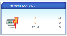
It is monitoring a caravan mover battery with a 105 Ah capacity, i think it will last during the winter on one load :smile:
Does anyone know why the three value are not show in the "data_request?id=lu_sdata" output?
It only outputs default values:
{
      "name": "MyMulti",
      "altid": "12;1",
      "id": 346,
      "category": 12,
      "subcategory": -1,
      "room": 0,
      "parent": 64
    },
While i would expect
{
      "name": "MyMulti",
      "altid": "12;1",
      "id": 346,
      "category": 12,
      "subcategory": -1,
      "room": 0,
      "parent": 64,
      "Impedance": 0,
      "Current": 0,
      "Voltage": 4.89
    },
I'm looking for a solution quite some time now, but I somehow miss a problem.
@Boots33 thanks for sharing, this project inspired me to have a monitor for my caravan battery :)
I have mine up and running now and did run in a small error present in your source code, on this line
present(ID_S_MULTIMETERV,V_VOLTAGE); // Register Sensor to gateway
The present function should contain sensor type (S_xxxx values) and V_VOLTAGE is a payload message type.
So i think the presentation function should look like this.
void presentation()
{
  sendSketchInfo("Battery Sensor", "1.1");    // Send the sketch version information to the gateway and Controller
  present(ID_S_MULTIMETERV, S_MULTIMETER);       // Register Sensor to gateway
}
Up and 'running':
@YFandS for some reason these smartmeters use a inverted implementation of the RS232 serial protocol. While Arduino's etc. use the standardized RS232 implementation.
As far is i known the UART (the "chip" doing the RSR232 decoding fro Arduino) does not supports inverted mode.
So yes a signal inverter is needed..
@knop Fabien tries to explain that the MySensors gateway is a major part of the MySensors-network it not just transmit the messages it actively contributes in, for example assigning node-id's and routing messages.
While the RFLink gateway only receives MySensors messages,
oke some pics..
Queue to get in :-)

The booth

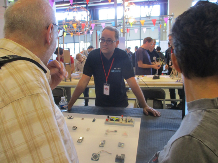

Yes we will be there soon and make some pictures!
@Woodside i think it is wise to bring all modules to same version.
50 07/11/17 13:58:38.725 luup_log:78: Arduino: Warning: Sensor has different library version than GW. Id: 1;255 <0x2e52a680>
i would suggest to start using the stable released version 2.1.1 and try again.
@Dick nice to hear
How it works:
As long as 'blockMotionTimer' is zero the motion debouncer is being monitored for any change.
When a PIR-change is detected the blockMotionTimer gets the value of the Arduino's internal milliseconds timer + the delay in milliseconds one want to wait.
This happes on this line: "blockMotionTimer = (millis() + SLEEP_TIME);"
See more about the millis() here
The blockMotionTimer is set back to zero the when mills() reaches the value set for time-out done with this check "if (blockMotionTimer < millis()) {" , and because the blockMotionTimer is non-zero the PIR value will not be checked during this period.
Expert note: since the milliseconds counter is returned in an unsigned long it will carry over one moment in time. Since Arduino stores it's ulong in 32 bits this means a carry over each 2^32 thus 4294967296 milliseconds. This is approx. every 50 days (49,71 days) So in theory this mechanism could result in a wrong (very short) delay, when timer is started precisely with the SLEEP_TIME period just before these 49,71 days. The result of millis() + SLEEP_TIME will then carry over and is immediate smaller than millis() on the next check. So be aware that this check if (blockMotionTimer > (millis() - SLEEP_TIME)) can result in a death-lock when blockMotionTimer = millis(); was set on the wrong moment in time.
@Dick mm look like a } on the wrong line. The } on line 126 should move up between line 119 and 120
(and there are 2 additional brackets)
The result should look like this
if (blockMotionTimer == 0) {
    if (motionsDebouncer.update()) {
        int value = motionsDebouncer.read();
        Serial.println( "PIR " + (String)value );
        gw.send( msgMOTION.set( value ), true ); // Also it might need inverted value
        blockMotionTimer = (millis() + SLEEP_TIME);
   }
} else {
        motionsDebouncer.update(); // dummy update to prevent false trigger after timer expires
        if (blockMotionTimer < millis()) {
            blockMotionTimer = 0;
        }
}
@Dick said in pir trigger must start delay:
Replace this piece of code
  if ( motionsDebouncer.update()) {
     int value = motionsDebouncer.read();
     Serial.println( "PIR " + (String)value );
     gw.send( msgMOTION.set( value ), true ); // Also it might need inverted value

 // Sleep until interrupt comes in on motion sensor. Send update.
   gw.sleep(DIGITAL_MOTION_SENSOR, CHANGE, SLEEP_TIME);
   }
with something like this
if (blockMotionTimer == 0) {
{
    if (motionsDebouncer.update()) {
        int value = motionsDebouncer.read();
        Serial.println( "PIR " + (String)value );
        gw.send( msgMOTION.set( value ), true ); // Also it might need inverted value
        blockMotionTimer = (millis() + SLEEP_TIME);
   } else {
        motionsDebouncer.update(); // dummy update to prevent false trigger after timer expires
        if (blockMotionTimer < millis()) {
            blockMotionTimer = 0;
        }
   }
}
Add this line at the top of your sketch (just below SLEEP_TIME)
unsigned long blockMotionTimer = 0;
Hi @OliverDog , yes this should work
Will it work with a single 4 pin RGB LED common cathode instead of a LED strip?
--> Uncomment this line "#define RGBW 1" to make it three color (RGB) in stead of four (RGBW).
Will it work with Home Assistant Controller like a ordinary RGB Light?
--> Should work with HAC since it presents it self as a RGB module
Could it run on batteries?
--> Yes why not, but please do read some forum posts about what to think about when running mysensors on batteries, there are several of them
@OliverDog here is a link to such a sketch (https://forum.mysensors.org/topic/2160/my-mysensors-rgbw-plug-in-has-an-init-problem)
@daniel.stancu you can do something like this
This examples servers 10 switches with 10 relays
/**
   The MySensors Arduino library handles the wireless radio link and protocol
   between your home built sensors/actuators and HA controller of choice.
   The sensors forms a self healing radio network with optional repeaters. Each
   repeater and gateway builds a routing tables in EEPROM which keeps track of the
   network topology allowing messages to be routed to nodes.

   Created by Henrik Ekblad <henrik.ekblad@mysensors.org>
   Copyright (C) 2013-2015 Sensnology AB
   Full contributor list: https://github.com/mysensors/Arduino/graphs/contributors

   Documentation: http://www.mysensors.org
   Support Forum: http://forum.mysensors.org

   This program is free software; you can redistribute it and/or
   modify it under the terms of the GNU General Public License
   version 2 as published by the Free Software Foundation.

 *******************************

   REVISION HISTORY
   Version 1.0 - Henrik Ekblad

   DESCRIPTION
   Example sketch showing how to control physical relays.
   This example will remember relay state after power failure.
   http://www.mysensors.org/build/relay
*/

// Enable debug prints to serial monitor
#define MY_DEBUG

// Enable and select radio type attached
#define MY_RADIO_NRF24
//#define MY_RADIO_RFM69

// Enable repeater functionality for this node
#define MY_REPEATER_FEATURE

#include <MySensors.h>

#define NUMBER_OF_RELAYS 10   // Total number of attached relays and switches

unsigned int  relay_pins[NUMBER_OF_RELAYS] = { 1, 2, 3, 4, 5, 6, 7, 8, A1, A2 };
#define RELAY_ON     1            // GPIO value to write to turn on attached relay
#define RELAY_OFF    0          // GPIO value to write to turn off attached relay

MyMessage  msg(0,  V_LIGHT);

#define BUTTON_PIN   A0
#define NO_BUTTON    255
// The followinging are interrupt-driven keypad reading functions
//  which includes DEBOUNCE ON/OFF mechanism, and continuous pressing detection
#define NUM_BUTTONS     NUMBER_OF_RELAYS
//keypad debounce parameter
#define DEBOUNCE_MAX 6
#define DEBOUNCE_ON  4
#define DEBOUNCE_OFF 2

// adc preset value, represent top value,incl. noise & margin,that the adc reads, when a key is pressed
// set noise & margin = 30 (0.15V@5V)
unsigned int  adc_key_val[NUM_BUTTONS] = { 50, 150, 200, 250, 300, 450, 500, 550, 600, 650 };


// debounce counters
byte button_count[NUM_BUTTONS];
// button status - pressed/released
byte button_status[NUM_BUTTONS];
// button on flags for user program
byte button_flag[NUM_BUTTONS];

byte lastButtonPressed = NO_BUTTON;


void before()
{
  for (int sensor = 0; sensor < NUMBER_OF_RELAYS; sensor++) {
    // Then set relay pins in output mode
    pinMode(relay_pins[sensor], OUTPUT);
    // Set relay to last known state (using eeprom storage)
    digitalWrite(relay_pins[sensor], loadState(sensor) ? RELAY_ON : RELAY_OFF);
  }
  pinMode(BUTTON_PIN, INPUT);
}

void setup()
{
  // reset button arrays
  for (byte i = 0; i < NUM_BUTTONS; i++)
  {
    button_count[i]  = 0;
    button_status[i] = 0;
    button_flag[i]   = 0;
  }
}

void presentation()
{
  // Send the sketch version information to the gateway and Controller
  sendSketchInfo("Relay 32", "1.0");

  for (int sensor = 0; sensor < NUMBER_OF_RELAYS; sensor++) {
    // Register all sensors to gw (they will be created as child devices)
    present(sensor + 1, S_BINARY);
  }
}


void loop()
{
  byte button = buttonPressed();

  // Check if there was a change of buttons presses
  if (button != lastButtonPressed)  {
    // YES we detected a change, only response when buttons was released
    if (button == NO_BUTTON) {
      msg.sensor = button + 1;
      send(msg.set(loadState(button) ? "0" : "1") );
    }
    lastButtonPressed = button;
  }

  wait(10);
}


char buttonPressed()
{
  for (byte i = 0; i < NUM_BUTTONS; i++)
  {
    if (button_flag[i] != 0) {
      button_flag[i] = 0;
      return i;
    }
  }
  return NO_BUTTON;
}

// Convert ADC value to key number
char get_key(unsigned int input)
{
  for (int k = 0; k < NUM_BUTTONS; k++)
  {
    if (input < adc_key_val[k]) {
      return k;
    }
  }
  return -1;    // No valid key pressed
}

void update_adc_key()
{
  unsigned int adc_key_in;
  char key_in;
  byte i;

  adc_key_in = analogRead(BUTTON_PIN);
  Serial.println(adc_key_in); // For debug only
  key_in = get_key(adc_key_in);

  for (i = 0; i < NUM_BUTTONS; i++)
  {
    if (key_in == i) {
      //one key is pressed
      if (button_count[i] < DEBOUNCE_MAX) {
        button_count[i]++;
        if (button_count[i] > DEBOUNCE_ON) {
          if (button_status[i] == 0) {
            button_flag[i] = 1;
            button_status[i] = 1; //button debounced to 'pressed' status
          }
        }
      }
    }
    else // no button pressed
    {
      if (button_count[i] > 0) {
        button_flag[i] = 0;
        button_count[i]--;
        if (button_count[i] < DEBOUNCE_OFF) {
          button_status[i] = 0;   //button debounced to 'released' status
        }
      }
    }
  }
}


void receive(const MyMessage &message)
{
  // We only expect one type of message from controller. But we better check anyway.
  if (message.type == V_STATUS) {
    // Change relay state
    digitalWrite(relay_pins[message.sensor - 1], message.getBool() ? RELAY_ON : RELAY_OFF);
    // Store state in eeprom
    saveState(message.sensor - 1, message.getBool());
    // Write some debug info
    Serial.print("Incoming change for sensor:");
    Serial.print(message.sensor);
    Serial.print(", New status: ");
    Serial.println(message.getBool());
  }
}
You have to connect the switches likes this, the value for R2 - Rx resistors around 100 ohms and 10k for R1.
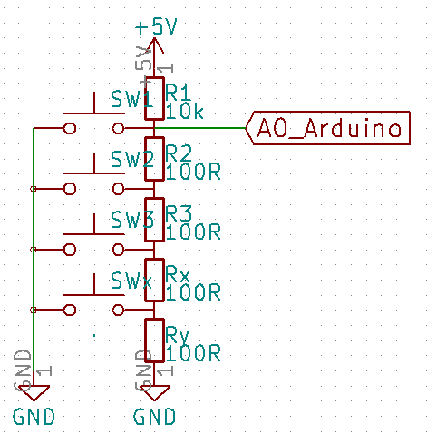
With the Serial.println debug statement one has to determine the correct analog values for the adc_key_val array (start with the lowest value first) by pressing the keys one by one, add approx 30 to the average values per button you see in the serial monitor too have some margin.
@Yveaux That is more or less in my backyard so i need to visit the booth!
Any help needed?
@mathieu no the shield is not mandatory you can just wire it up yourselves.
But be careful the CC2500 does requires voltage shifting it will brake with TTL level.
Here is the schematic
I'm not familiair with this MD7105 replacement.
One general tip for all user or the Livingcolor controller. It took my 2 broken Arduino Uno's to find out why they stopped working after 2 weeks. The onboard 3v3 power convertor is to weak ans will break. So i added my own 3v3 power regulator.